EP0468800B1 - Tête optique pour appareil à reproduire des informations magnéto-optiques - Google Patents
Tête optique pour appareil à reproduire des informations magnéto-optiques Download PDFInfo
- Publication number
- EP0468800B1 EP0468800B1 EP91306824A EP91306824A EP0468800B1 EP 0468800 B1 EP0468800 B1 EP 0468800B1 EP 91306824 A EP91306824 A EP 91306824A EP 91306824 A EP91306824 A EP 91306824A EP 0468800 B1 EP0468800 B1 EP 0468800B1
- Authority
- EP
- European Patent Office
- Prior art keywords
- light beam
- optical
- light
- magneto
- glass
- Prior art date
- Legal status (The legal status is an assumption and is not a legal conclusion. Google has not performed a legal analysis and makes no representation as to the accuracy of the status listed.)
- Expired - Lifetime
Links
- 230000003287 optical effect Effects 0.000 title claims description 51
- 230000010287 polarization Effects 0.000 claims description 54
- 239000011521 glass Substances 0.000 claims description 50
- 239000013078 crystal Substances 0.000 claims description 49
- 239000004065 semiconductor Substances 0.000 claims description 33
- 239000010453 quartz Substances 0.000 description 13
- VYPSYNLAJGMNEJ-UHFFFAOYSA-N silicon dioxide Inorganic materials O=[Si]=O VYPSYNLAJGMNEJ-UHFFFAOYSA-N 0.000 description 13
- 230000005374 Kerr effect Effects 0.000 description 7
- 238000001514 detection method Methods 0.000 description 7
- 230000008859 change Effects 0.000 description 6
- 230000009467 reduction Effects 0.000 description 5
- 230000004075 alteration Effects 0.000 description 4
- 230000000694 effects Effects 0.000 description 4
- 238000002834 transmittance Methods 0.000 description 4
- 239000000463 material Substances 0.000 description 3
- 101100110018 Arabidopsis thaliana ASK3 gene Proteins 0.000 description 2
- 230000006870 function Effects 0.000 description 2
- 239000010409 thin film Substances 0.000 description 2
- 101000838578 Homo sapiens Serine/threonine-protein kinase TAO2 Proteins 0.000 description 1
- 102100028949 Serine/threonine-protein kinase TAO2 Human genes 0.000 description 1
- 230000003321 amplification Effects 0.000 description 1
- 238000010420 art technique Methods 0.000 description 1
- 230000015572 biosynthetic process Effects 0.000 description 1
- 238000010276 construction Methods 0.000 description 1
- 238000000151 deposition Methods 0.000 description 1
- 239000010408 film Substances 0.000 description 1
- 238000003199 nucleic acid amplification method Methods 0.000 description 1
- 238000000926 separation method Methods 0.000 description 1
Images


Classifications
-
- G—PHYSICS
- G11—INFORMATION STORAGE
- G11B—INFORMATION STORAGE BASED ON RELATIVE MOVEMENT BETWEEN RECORD CARRIER AND TRANSDUCER
- G11B7/00—Recording or reproducing by optical means, e.g. recording using a thermal beam of optical radiation by modifying optical properties or the physical structure, reproducing using an optical beam at lower power by sensing optical properties; Record carriers therefor
- G11B7/12—Heads, e.g. forming of the optical beam spot or modulation of the optical beam
- G11B7/135—Means for guiding the beam from the source to the record carrier or from the record carrier to the detector
- G11B7/1356—Double or multiple prisms, i.e. having two or more prisms in cooperation
-
- G—PHYSICS
- G02—OPTICS
- G02B—OPTICAL ELEMENTS, SYSTEMS OR APPARATUS
- G02B5/00—Optical elements other than lenses
- G02B5/04—Prisms
-
- G—PHYSICS
- G11—INFORMATION STORAGE
- G11B—INFORMATION STORAGE BASED ON RELATIVE MOVEMENT BETWEEN RECORD CARRIER AND TRANSDUCER
- G11B11/00—Recording on or reproducing from the same record carrier wherein for these two operations the methods are covered by different main groups of groups G11B3/00 - G11B7/00 or by different subgroups of group G11B9/00; Record carriers therefor
- G11B11/10—Recording on or reproducing from the same record carrier wherein for these two operations the methods are covered by different main groups of groups G11B3/00 - G11B7/00 or by different subgroups of group G11B9/00; Record carriers therefor using recording by magnetic means or other means for magnetisation or demagnetisation of a record carrier, e.g. light induced spin magnetisation; Demagnetisation by thermal or stress means in the presence or not of an orienting magnetic field
- G11B11/105—Recording on or reproducing from the same record carrier wherein for these two operations the methods are covered by different main groups of groups G11B3/00 - G11B7/00 or by different subgroups of group G11B9/00; Record carriers therefor using recording by magnetic means or other means for magnetisation or demagnetisation of a record carrier, e.g. light induced spin magnetisation; Demagnetisation by thermal or stress means in the presence or not of an orienting magnetic field using a beam of light or a magnetic field for recording by change of magnetisation and a beam of light for reproducing, i.e. magneto-optical, e.g. light-induced thermomagnetic recording, spin magnetisation recording, Kerr or Faraday effect reproducing
- G11B11/10532—Heads
- G11B11/10541—Heads for reproducing
- G11B11/10543—Heads for reproducing using optical beam of radiation
-
- G—PHYSICS
- G11—INFORMATION STORAGE
- G11B—INFORMATION STORAGE BASED ON RELATIVE MOVEMENT BETWEEN RECORD CARRIER AND TRANSDUCER
- G11B11/00—Recording on or reproducing from the same record carrier wherein for these two operations the methods are covered by different main groups of groups G11B3/00 - G11B7/00 or by different subgroups of group G11B9/00; Record carriers therefor
- G11B11/10—Recording on or reproducing from the same record carrier wherein for these two operations the methods are covered by different main groups of groups G11B3/00 - G11B7/00 or by different subgroups of group G11B9/00; Record carriers therefor using recording by magnetic means or other means for magnetisation or demagnetisation of a record carrier, e.g. light induced spin magnetisation; Demagnetisation by thermal or stress means in the presence or not of an orienting magnetic field
- G11B11/105—Recording on or reproducing from the same record carrier wherein for these two operations the methods are covered by different main groups of groups G11B3/00 - G11B7/00 or by different subgroups of group G11B9/00; Record carriers therefor using recording by magnetic means or other means for magnetisation or demagnetisation of a record carrier, e.g. light induced spin magnetisation; Demagnetisation by thermal or stress means in the presence or not of an orienting magnetic field using a beam of light or a magnetic field for recording by change of magnetisation and a beam of light for reproducing, i.e. magneto-optical, e.g. light-induced thermomagnetic recording, spin magnetisation recording, Kerr or Faraday effect reproducing
- G11B11/1055—Disposition or mounting of transducers relative to record carriers
- G11B11/10576—Disposition or mounting of transducers relative to record carriers with provision for moving the transducers for maintaining alignment or spacing relative to the carrier
-
- G—PHYSICS
- G11—INFORMATION STORAGE
- G11B—INFORMATION STORAGE BASED ON RELATIVE MOVEMENT BETWEEN RECORD CARRIER AND TRANSDUCER
- G11B7/00—Recording or reproducing by optical means, e.g. recording using a thermal beam of optical radiation by modifying optical properties or the physical structure, reproducing using an optical beam at lower power by sensing optical properties; Record carriers therefor
- G11B7/12—Heads, e.g. forming of the optical beam spot or modulation of the optical beam
- G11B7/135—Means for guiding the beam from the source to the record carrier or from the record carrier to the detector
- G11B7/1395—Beam splitters or combiners
Definitions
- the present invention relates to an optical head for a magneto-optical information reproducing apparatus for reproducing information magnetically recorded on a magneto-optical recording medium by utilizing a magneto-optical effect.
- the study and development of an optical memory for recording and reproducing information by a semiconductor laser beam for use as a high record density memory have recently been vigorously done, and particularly a magneto-optical recording medium which permits erasing and rewriting of information is considered promising.
- information is magnetically recorded by utilizing a local temperature rise on a magnetic thin film by spot irradiation of a laser beam, and the information is reproduced by a magneto-optical effect (particularly, Kerr effect).
- the Kerr effect is defined as a phenomenon in which a polarization plane is rotated when a light is reflected by a magnetic recording medium.
- a light beam from a semiconductor laser 102 is collimated by a collimator lens 103, reflected by a beam splitter 104, and focused by an objective lens 105 onto a magneto-optical disk 106 which is a magneto-optical recording medium.
- the light beam reflected by the magneto-optical disk 106 passes through the objective lens 105 and the beam splitter 104 and is split by a beam splitter 107 into two light beams, a reflected beam and a transmitted beam.
- the reflected beam is directed to a servo error detection photosensor 109 through a lens 108.
- the photo-sensor 109 produces a detection signal in accordance with a shape of a spot on a photo-sensing area and supplies it to a servo error signal generator 112, which in turn produces a focusing error signal and a tracking error signal which are used to drive the objective lens 105 to a desired position by an actuator (not shown).
- the light beam transmitted through the beam splitter 107 is directed to a one-half wavelength plate 111, split by a Wollaston prism 113 into two light beams having orthogonal polarization components, and they are directed to a photo-detector 115 through a lens 114.
- the photo-detector 115 has two detectors for the above two light beams, and produces two detection output signals representing the changes in the respective polarization components and supplies them to a reproduced signal detector 116, which compares the two detection output signals to detect a rotation (Kerr rotation of the polarization plane of the light beam caused in the reflection by the vertically magnetized film of the magneto-optical disk 106) so that a reproduction signal representing the rotation is produced.
- the Wollaston prism 113 is constructed by joining a quartz 120 having an optical axis 130 parallel to a Y-axis and a quartz 121 having an optical axis 131 parallel to a Z-axis.
- An incident light which travels along an X-axis is a linearly polarized light which is polarized in an XY plane.
- the one-half wavelength plate 111 is set to rotate the polarization direction of the incident light by 45 degrees.
- Fig. 3 shows a sectional view of the prior art Wollaston prism 113 shown in Fig. 2.
- incident light polarized in the direction of 45 degrees with respect to the Y-axis travels from the quartz 120 to the quartz 121, a projection component to the Y-axis is sequentially subjected to the actions of an extraordinary light refractive index and an ordinary light refractive index and exits as a linearly polarized light 122 polarized in the XY-plane.
- a projection component of the incident light to the Z-axis is sequentially subjected to the actions of the ordinary light refractive index and the extraordinary light refractive index, and exits as a linearly polarized light 123 which is polarized in a plane orthogonal to the XY plane.
- the incident light which is polarized in the direction of 45 degrees with respect to the Y-axis exits as the two linearly polarized lights 122 and 123 which are orthogonal to each other and have the same intensity.
- the polarization direction of the light beam reflected by the magneto-optical disk 106, prior to the entrance into the one-half wavelength plate 111 is deviated from the Y-axis by ⁇ K or - ⁇ K due to the influence of the Kerr effect.
- the polarization direction of the incident light periodically changes between the direction corresponding to ⁇ K and the direction corresponding to - ⁇ K
- the two exit lights 122 and 123 have the same amplitude and opposite phases. Accordingly, by differencing the outputs from the detectors for the two exit lights, a light intensity variation (noise) due to a foreign material on the magneto-optical disk is elliminated and a C/N ratio of the reproduced signal is improved.
- the beam splitter 107 is required to produce the light beam for generating the servo signal and the light beam for generating the reproduction signal.
- the one-half wavelength plate 111 is required to set the desired polarization direction of the light beam applied to the Wollaston prism 113.
- a large number of steps are required for the adjustment of the angle of the one-half wavelength plate 111.
- EP-A-0395832 (prior art under Article 54(3)EPC) discloses an optical head for use in a magneto optical recording/producing device comprising a semiconductor laser, and means for focusing the light beam from the semiconductor laser into a spot on the magneto-optical recording medium.
- a light splitting means is provided to split the light beam reflected by the recording medium into two light beams of different polarisation.
- an object of the present invention to provide an optical head for magneto-optical information reproducing apparatus which permits the reproduction of a high quality signal by the use of a crystal element and facilitates the reduction of weight, size and thickness.
- an optical head for a magneto-optical information reproducing apparatus comprising:
- an optical element comprising an optical element comprising light beam splitting means for splitting an incident light beam into a first light beam having a polarization component in a first direction substantially 45° with respect to the polarization direction of said incident light beam and into a second light beam having a polarization component in a directional orthogonal to the first direction;
- a spot light from a semiconductor laser which is a light source is irradiated to a magnetic thin film of a magneto-optical recording medium, information is recorded on the recording medium by a local temperature rise of the recording medium, and the information is reproduced by a magneto-optical effect (particularly, a Kerr effect).
- the Kerr effect is defined as a phenomenon in which a polarization plane is rotated when the light is reflected by the magneto-optical recording medium.
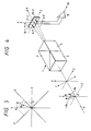
- An optical element 1 which is a light beam split means for splitting the light beam reflected by the recording medium comprises a first glass 2, a uniaxial crystal 3 and a second glass 4 which are arranged in this sequence in the direction of incidence.
- a light beam 5 applied to the optical element 1 is a linearly polarized light which is emitted by a semiconductor laser and reflected by the recording medium, and has a polarization plane thereof rotated by a small angle ⁇ K with respect to a Y-axis depending on the presence or absence of the information recorded by the Kerr effect.
- An optical axis 7 of the uniaxial crystal 3 is set in the direction of 45 degrees with respect to the Y-axis and has an extraordinary light refractive index n E in the direction of the optical axis and an ordinary light refractive index n 0 in a direction orthogonal to the above direction.
- the direction of the optical axis 7 of the uniaxial crystal 3 is in the direction of substantially 45 degrees with respect to the polarization direction of the semiconductor laser which is the light source.
- the normal lines to the joint planes of the first glass 2 and the uniaxial crystal 3, and the second glass 4 and the uniaxial crystal 3, respectively, are in the plane in which the two light beams 6-1 and 6-2 are contained.
- the direction of the optical axis of the uniaxial crystal 3 is represented by an E-axis, and a direction orthogonal thereto is represented by an O-axis.
- the incident light beam 5 is decomposed to two orthogonal amplitude components, a Fresnel component R and a Kerr component K.
- the light beams of the respective amplitude components cause different differences of refractive indices n E -n and n 0 -n at the interfaces of the glasses 2 and 4 (having the refractive index n) and the uniaxial crystal 3. Thus, they are split to two light beams 6-1 and 6-2 in accordance with Snell's law (see Fig. 4). They are detected by photo-detectors 10-1 and 10-2.
- the two light beams comprise a first light beam having a polarization component in the direction of substantially 45 degrees with respect to the polarization direction of the semiconductor laser, and a second light beam having a polarization component in the direction orthogonal to the above direction.
- the photo-detectors 10-1 and 10-2 are also used to detect a servo signal (focusing and tracking signal) for positioning the fine light spot on the magneto-optical medium (not shown), in addition to the detection of the magneto-optical signal.
- the shape of the light beam or the light intensity distribution on the photo-detector is usually detected.
- the light beam is precisely positioned to the multi-divided photo-detector and the position of the light spot on the recording medium is controlled such that the operation values of the outputs of the respective photo-detectors reach the target values.
- a magneto-optical information reproducing apparatus which uses the light beam split element 1 of the present invention is explained with reference to Figs. 6A and 6B.
- a polarization beam splitter is vapor-deposited on a joint plane of the glass 2 and the uniaxial crystal 3.
- the linearly polarized light beam emitted from the semiconductor laser 12 is collimated by a collimator lens 13.
- the polarization direction of the semiconductor laser is normal to the plane of the drawing in the front view (Fig. 6A).
- the light beam applied to the light beam split element 1 with the S polarization is reflected approximately 80% and it is directed to a mirror 14.
- the light beam reflected by the mirror 14 is focused by an objective lens 15 to a fine spot on a predetermined track of the recording medium.
- the light spot is positioned by an actuator (not shown) by driving the objective lens perpendicularly to the track and along the optical axis.
- the reflected light beam which contains the magneto-optical signal information on the recording medium 16 is collimated by the objective lens 15, deflected by the mirror 14 and again directed to the light beam split element 1.
- the magneto-optical signal information is converted to a P polarization component by the light beam split element 1.
- the P polarization component is transmitted substantially 100% and the S polarization component is transmitted 20%. Accordingly, the Kerr rotation angle is amplified so that a high S/N ratio is attained.
- the present embodiment is featured by the unnecessity of the one-half wavelength plate and the formation of the servo signal detection light beam 6-1 and the reproduction signal detection light beam 6-2 by the single optical element, that is, the light beam split element 1. It attains the reduction of the number of parts and the reduction of the number of assembling and adjusting steps compared to those of the prior art optical head.
- the shape or the light intensity distribution of the light beam on the photo-detector is usually detected as the servo signal.
- the light beam is precisely positioned on the multi-divided photo-detectors and the position of the light spot is controlled such that the operation values of the outputs of the respective photo-detectors reach the target values.
- numerals 6-1 and 6-2 denote two light beams split by the optical element 1.
- Solid lines show light paths of projected images 11-1 and 11-2 when the light beams 6-1 and 6-2 are precisely positioned on the photo-detectors.
- 4-split sensors are used as the photo-detectors 10-1 and 10-2 and they are exactly positioned on the split lines as shown in Fig. 8, the operation values at the outputs of the respective photo-detectors are the target values of control, and the light spot on the recording medium is correctly focused and tracked on the desired track.
- the semiconductor laser (not shown) which is used as the light source usually has a characteristic by which a wavelength varies with a temperature and an output.
- the wavelength-temperature characteristic is normally 0.2 ⁇ 0.3 nm/°C.
- the waveform variation of 12 ⁇ 18 nm is included.
- the output changes from approximately 3 mW to approximately 30 mW, and the variation of wavelength is normally 3 ⁇ 6 nm.
- the extraordinary light refractive index n 0 of the uniaxial crystal 3 and the refractive index n of the glasses 2 and 4 also vary.
- the change in the light beam exit angle from the light beam split element is sufficiently small so that the magneto-optical signal information is correctly and stably reproduced even if the wavelength of the semiconductor laser which is the light source varies with the temperature or the output.
- the light beam from the semiconductor laser is focused to a fine spot on the magneto-optical recording medium, and the light beam reflected by the record medium is split by the light beam separation means to a first light beam having a polarization direction which is in the direction of approximately 45 degrees with respect to the polarization direction of the semiconductor laser, and to a second light beam having a polarization component which is orthogonal to the above direction.
- the light beam split means comprises a first glass, a uniaxial crystal and a second glass arranged in this sequence along the direction of incidence of the light beam.
- Normal lines to the joint planes of the first glass and the uniaxial crystal, and the second glass and the uniaxial crystal, respectively, are in the plane in which the first and second light beams are contained, and the optical axis of the uniaxis crystal is set in the direction of approximately 45 degrees with respect to the polarization direction of the semiconductor laser.
- the first and second glasses and the uniaxial crystal have refractive indices, scatterings and joint angles such that the light beam exit angles from the light beam split means are equal for the first and second wavelengths of the semiconductor laser, for at least one of the first and second light beams.
- the change in the light beam exit angle from the light beam split element is sufficiently small even if the wavelength of the semiconductor laser varies with the temperature or the output.
- the deviation of the light beam on the photo-detector which detects the servo signal is small, and the magneto-optical signal information can be exactly and stably reproduced.
- the light beam split element 1 of the present invention comprises a first glass 2, a uniaxial crystal 3 and a second glass 4 arranged in this sequence in the direction of incidence of the light beam.
- a reflected light beam 5 from a magneto-optical recording medium passes through the light beam split element 1.
- the direction of the Kerr rotation angle caused thereby is identical to that of Fig. 4.
- a basic structure of the light beam split element is identical to that of Fig. 4.
- One light beam 6-1 (the other is not shown) of the two light beams split by the light beam split element 1 is explained in detail.
- the explanation for the one light beam is equally applicable to the other light beam, and in the photo-detectors 10-1 and 10-2 shown in Fig. 8, necessary servo signal information (for focusing and tracking) may be obtained by using either one of the light beams. Accordingly, the explanation for one light beam is sufficient to understand the present invention.
- the refractive index of the glass 2 is n 1j
- the refractive index of the uniaxial crystal 3 is n 2j
- the refractive index of the glass 4 is n 3j (where the argument j means first and second wavelengths)
- the uniaxial crystal 3 has an extraordinary light refractive index n E and an ordinary light refractive index n 0
- n 2j means one of them by the reason described above.
- a difference between the first wavelength ⁇ 1 and the second wavelength ⁇ 2 may be approximately ⁇ 15 nm taking the wavelength variation of ⁇ 6 ⁇ ⁇ 9 nm due to the temperature change of the semiconductor laser and the wavelength variation of 3 ⁇ 6 nm due to the output change into consideration.
- a first example is shown below.
- the light beam exit angle of the light beam split element 1 is approximately zero degree, and the influence by the aberration is reduced even if the lens is arranged behind the light beam split element.
- SK12 is used for the glass 2
- quartz is used for the uniaxial crystal
- BK7 is used for the glass 4.
- the photo-detector 10-1 or 10-2 may be used to detect the servo signal. Further, since the exit light angle is close to zero degree, the aberration hardly occurs even if the lens (not shown) is arranged behind the light beam split element 1. Even if the material of the glasses 2 and 4 is changed, the substantially same characteristic is attained.
- ⁇ 1 790 nm
- ⁇ 2 805 nm
- n 11 1.54149
- n 12 1.54118 Quartz (Extraordinary)
- n 21 1.54749
- n 22 1.54718 Quartz (Ordinary)
- n 21 1.53859
- n 22 1.53829
- the deviation of the exit light angle from the light beam split means 1 for the wavelength variation is also small for the extraordinary light and the ordinary light, and either the photo-detector 10-1 or 10-2 may be used to detect the servo signal. Further, since the exit light angle is close to zero degree, the aberration hardly occurs even if the lens (not shown) is arranged behind the light beam split element 1.
- n 1j ⁇ n 3j are given below.
- ⁇ 1 790 nm
- ⁇ 2 805 nm
- n 21 1.54749
- n 22 1.54718 Quartz (Ordinary)
- n 21 1.53859
- n 22 1.53829
- the angle is +0.53° for the extraordinary light and -0.53° for the ordinary light.
- the deviation of the exit light angle from the light beam split means 1 for the wavelength variation is also small for the extraordinary light and the ordinary light, and either the photo-detector 10-1 or 10-2 may be used to detect the servo signal. Further the aberration hardly occurs even if the lens (not shown) is arranged behind the light beam split element 1.
- the configuration of the magneto-optical information reproducing apparatus which uses the light beam split element 1 of the present invention is similar to that shown in Fig. 6.
- the reflected light beam from the recording medium is split into the light beams 6-1 and 6-2 having two polarization components which are orthogonal to each other, at the joint planes of the glasses 2 and 4 and the uniaxial crystal 3.
- the split angle of the light beams is approximately 1 degree.
- the light beams 6-1 and 6-2 are focused by the lens 17 onto the photo-detectors 10-1 and 10-2.
- the magneto-optical signal is produced by the differential output of the photo-detectors, and the servo signal is produced by at least one of the photo-detector.
- the angle deviation of the light beams 6-1 and 6-2 split by the light beam split element 1 is very small, the deviation of the light beam on the photo-detector is small even if the wavelength of the semiconductor laser 12 varies with the temperature or the output, and the stable and correct reproduction of the magneto-optical signal is attained.
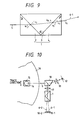
- Fig. 10 shows other embodiment of the optical head for the magneto-optical information reproducing apparatus of the present invention.
- the linearly polarized light beam emitted from the semiconductor laser 12 is collimated by the collimator lens 13.
- the polarization direction of the semiconductor laser is in the plane of the drawing.
- the polarization beam splitter 18 has a beam reshaping function so that the incident light is reshaped into a light beam having a substantially isotropic intensity distribution.
- the light beam transmitted through the polarization beam splitter 18 is directed to the mirror 14.
- the reflected light beam which contains the magneto-optical signal information on the recording medium 16 is again directed to the polarization beam splitter 18 through a path which is similar to that of the embodiment of Fig. 6.
- the magneto-optical signal information is the S-polarization component for to polarization beam splitter 18. Since the S-polarization component is reflected substantially 100% and the P-polarization component is reflected 20% by the polarization beam splitter, the amplification of the Kerr effect takes place and a high S/N ratio is attained.
- the light beam directed to the light beam split element 1 through the lens 17 is split into the light beams 6-1 and 6-2 having two orthogonal polarization components as it is in the embodiment of Fig. 6, and they are focused onto the photo-detectors 10-1 and 10-2.
- the deviation of the angle of the light beams 6-1 and 6-2 split by the light beam split element 1 is very small even if the wavelength of the semiconductor laser l2 varies with the temperature or the output. Accordingly, the deviation of the light beam on the photo-detector is small and the stable and correct reproduction of the magneto-optical signal is attained.
- the refractive indices, the scatterings and the joint angles of the crystal and the glasses are selected such that the deviation of the light beam exit angle from the light beam split element is sufficiently small even if the wavelength of the semiconductor laser which is the light source varies with the temperature or the output, and the deviation of the light beam on the photo-detector which detects the servo signal is sufficiently small. Accordingly, the magneto-optical signal information can be correctly and stably reproduced.
- the polarization beam splitter and the light beam split element can be integrated by vapor-depositing the polarization beam splitter on the joint plane of the glass and the crystal so that the reduction of weight, size and cost of the optical head is facilitated.
Landscapes
- Physics & Mathematics (AREA)
- Optics & Photonics (AREA)
- General Physics & Mathematics (AREA)
- Optical Head (AREA)
Claims (6)
- Tête optique pour appareil magnéto-optique de reproduction d'information comprenant :un laser (12) à semiconducteur ;des moyens (15) pour focaliser un faisceau lumineux provenant dudit laser (12) à semiconducteur sous la forme d'une trace fine sur un support d'enregistrement magnéto-optique ; etdes moyens (11) de séparation de faisceau lumineux pour séparer le faisceau (5) lumineux réfléchi par ledit support d'enregistrement en un premier faisceau (6-1) lumineux ayant une composante de polarisation (P) dans une première direction (E) sensiblement égale à 45 degrés par rapport à la direction de polarisation dudit laser (12) à semiconducteur, et en un second faisceau (6-2) lumineux ayant une composante de polarisation (S) dans une direction (0) orthogonale à la première direction (E) ;la tête optique étant caractérisée en ce que :lesdits moyens (1) de séparation de faisceau lumineux comprennent un premier verre (2), un cristal (3) uniaxe et un second verre (4) agencés dans cet ordre dans la direction d'incidence du faisceau (5) lumineux provenant dudit support d'enregistrement magnéto-optique ;les normales aux interfaces entre ledit premier verre (2) et ledit cristal (3) uniaxe, et ledit second verre (4) et ledit cristal (3) uniaxe, qui passent respectivement par l'axe optique des moyens (1) de séparation de faisceau lumineux, sont contenues dans un plan (X-Z) contenant les premier et second faisceaux (6-1, 6-2) lumineux ; etl'axe (7) optique dudit cristal (3) uniaxe est orienté dans ladite première direction (E).
- Tête optique pour appareil magnéto-optique de reproduction d'information selon la revendication 1, dans lequel lesdits premier et second verres (2, 4), et ledit cristal (3) uniaxe ont des indices de réfraction (n), des diffusions et des angles joints tels que les angles d'émergence du faisceau lumineux desdits moyens (1) de séparation de faisceau lumineux sont sensiblement constants, indépendamment des variations de longueur d'onde de la lumière provenant dudit laser (12) à semiconducteur.
- Tête optique pour appareil magnéto-optique de reproduction d'information selon la revendication 1, dans lequel une séparatrice de faisceau à polarisation est déposée en phase vapeur sur l'interface entre ledit premier verre (2) et ledit cristal (3) uniaxe.
- Tête optique pour appareil magnéto-optique de reproduction d'information selon la revendication 1, dans lequel les premier et second faisceaux (6-1, 6-2) lumineux séparés par lesdits moyens (1) de séparation de faisceau lumineux sont sensiblement parallèles au faisceau lumineux incident sur lesdits moyens (1) de séparation de faisceau lumineux et réfléchis par le support d'enregistrement.
- Appareil de reproduction optique comprenant une tête optique selon l'une quelconque des revendications précédentes.
- Élément optique comprenant des moyens (1) de séparation de faisceau lumineux pour séparer un faisceau lumineux incident en un premier faisceau (6-1) lumineux ayant une composante de polarisation (P) dans une première direction (E) formant un angle sensiblement égal à 45 degrés par rapport à la direction de polarisation dudit faisceau lumineux incident et en un second faisceau (6-2) lumineux ayant une composante de polarisation (S) dans une direction (0) orthogonale à la première direction (E) ;l'élément étant caractérisé en ce que les moyens (1) de séparation de faisceau comprennent un premier verre (2), un cristal (3) uniaxe et un second verre (4) agencés dans cet ordre dans la direction d'incidence du faisceau lumineux sur les moyens (1) de séparation de faisceau lumineux ;dans lequel les normales aux interfaces entre ledit premier verre (2) et ledit cristal (3) uniaxe, et ledit second verre (4) et ledit cristal (3) uniaxe, respectivement, qui passent par l'axe (X) optique des moyens (1) de séparation de faisceau lumineux, sont contenues dans un plan (X-Z) contenant les premier et second faisceaux (6-1, 6-2) lumineux ; etl'axe (7) optique dudit cristal (3) uniaxe est fixé dans ladite première direction (E).
Applications Claiming Priority (2)
| Application Number | Priority Date | Filing Date | Title |
|---|---|---|---|
| JP2196105A JP2798185B2 (ja) | 1990-07-26 | 1990-07-26 | 光磁気式情報再生装置用光学ヘッド |
| JP196105/90 | 1990-07-26 |
Publications (2)
| Publication Number | Publication Date |
|---|---|
| EP0468800A1 EP0468800A1 (fr) | 1992-01-29 |
| EP0468800B1 true EP0468800B1 (fr) | 1996-11-20 |
Family
ID=16352318
Family Applications (1)
| Application Number | Title | Priority Date | Filing Date |
|---|---|---|---|
| EP91306824A Expired - Lifetime EP0468800B1 (fr) | 1990-07-26 | 1991-07-25 | Tête optique pour appareil à reproduire des informations magnéto-optiques |
Country Status (4)
| Country | Link |
|---|---|
| US (1) | US5293371A (fr) |
| EP (1) | EP0468800B1 (fr) |
| JP (1) | JP2798185B2 (fr) |
| DE (1) | DE69123192T2 (fr) |
Families Citing this family (16)
| Publication number | Priority date | Publication date | Assignee | Title |
|---|---|---|---|---|
| JPH05114191A (ja) * | 1991-10-22 | 1993-05-07 | Canon Inc | 複数ビーム光ヘツド |
| JPH0612719A (ja) * | 1992-06-29 | 1994-01-21 | Canon Inc | 光ヘッド及び情報読取装置 |
| US5694385A (en) * | 1993-09-24 | 1997-12-02 | Ricoh Comany, Ltd. | Optical pickup apparatus |
| JP3167066B2 (ja) * | 1993-10-06 | 2001-05-14 | キヤノン株式会社 | 光記録再生装置 |
| JPH07129992A (ja) * | 1993-11-06 | 1995-05-19 | Asahi Optical Co Ltd | 情報記録再生装置 |
| JP3548259B2 (ja) * | 1994-04-07 | 2004-07-28 | ペンタックス株式会社 | 光磁気ヘッド装置 |
| US5541906A (en) * | 1994-07-29 | 1996-07-30 | Olympus Optical Co., Ltd. | Optical head for magneto-optical record medium |
| JPH0950653A (ja) * | 1995-08-04 | 1997-02-18 | Asahi Optical Co Ltd | 光磁気ヘッド装置 |
| WO1999016061A1 (fr) * | 1997-09-22 | 1999-04-01 | Seagate Technology, Inc. | Procede et appareil de focalisation differentielle et de poursuite push-pull destine a des memoires magneto-optiques |
| JP3607836B2 (ja) * | 1999-03-31 | 2005-01-05 | シャープ株式会社 | 光ピックアップ装置 |
| FR2802696B1 (fr) | 1999-12-17 | 2002-07-19 | Thomson Csf | Lecteur magneto optique optimise par le polariseur de lumiere incidente |
| US20040001399A1 (en) * | 2002-06-26 | 2004-01-01 | Pentax Corporation | Optical head for optical disc drive |
| JP2005166195A (ja) * | 2003-12-04 | 2005-06-23 | Canon Inc | 光情報記録再生装置及び光情報記録再生方法 |
| JP2006331471A (ja) * | 2005-05-23 | 2006-12-07 | Canon Inc | 光情報記録再生装置 |
| US7680013B2 (en) * | 2005-11-29 | 2010-03-16 | Canon Kabushiki Kaisha | Optical information recording and reproducing apparatus |
| US7791986B2 (en) * | 2006-03-15 | 2010-09-07 | Canon Kabushiki Kaisha | Optical information recording/reproducing apparatus |
Citations (2)
| Publication number | Priority date | Publication date | Assignee | Title |
|---|---|---|---|---|
| EP0309232A2 (fr) * | 1987-09-21 | 1989-03-29 | Sharp Kabushiki Kaisha | Appareil d'enregistrement et de reproduction d'information optique |
| EP0395832A2 (fr) * | 1989-05-02 | 1990-11-07 | Pioneer Electronic Corporation | Tête optique |
Family Cites Families (9)
| Publication number | Priority date | Publication date | Assignee | Title |
|---|---|---|---|---|
| JPH07101523B2 (ja) * | 1986-09-12 | 1995-11-01 | キヤノン株式会社 | 光磁気信号再生装置 |
| US4813032A (en) * | 1986-10-17 | 1989-03-14 | Canon Kabushiki Kaisha | Magneto-optical information reproducing apparatus in which the azimuth angle of the transmission axis of an analyzer is optimized so that the C/N ratio of a reproducing signal is maximum |
| JPH0778916B2 (ja) * | 1986-10-17 | 1995-08-23 | キヤノン株式会社 | 光磁気情報再生装置 |
| JPH0777038B2 (ja) * | 1986-12-25 | 1995-08-16 | ソニー株式会社 | 光学ピツクアツプ装置 |
| JPH01116930A (ja) * | 1987-10-29 | 1989-05-09 | Canon Inc | 光ビーム位置検出装置 |
| FR2639460B1 (fr) * | 1988-11-21 | 1993-05-21 | Ricoh Kk | Appareil d'enregistrement/reproduction optique |
| JPH0718963Y2 (ja) * | 1989-05-16 | 1995-05-01 | ブラザー工業株式会社 | 光学式表面粗さ測定装置 |
| JP2984004B2 (ja) * | 1989-08-28 | 1999-11-29 | ソニー株式会社 | カッテングマシン |
| US5187543A (en) * | 1990-01-19 | 1993-02-16 | Zygo Corporation | Differential displacement measuring interferometer |
-
1990
- 1990-07-26 JP JP2196105A patent/JP2798185B2/ja not_active Expired - Fee Related
-
1991
- 1991-07-19 US US07/733,161 patent/US5293371A/en not_active Expired - Lifetime
- 1991-07-25 DE DE69123192T patent/DE69123192T2/de not_active Expired - Fee Related
- 1991-07-25 EP EP91306824A patent/EP0468800B1/fr not_active Expired - Lifetime
Patent Citations (2)
| Publication number | Priority date | Publication date | Assignee | Title |
|---|---|---|---|---|
| EP0309232A2 (fr) * | 1987-09-21 | 1989-03-29 | Sharp Kabushiki Kaisha | Appareil d'enregistrement et de reproduction d'information optique |
| EP0395832A2 (fr) * | 1989-05-02 | 1990-11-07 | Pioneer Electronic Corporation | Tête optique |
Also Published As
| Publication number | Publication date |
|---|---|
| JP2798185B2 (ja) | 1998-09-17 |
| JPH0489643A (ja) | 1992-03-23 |
| DE69123192D1 (de) | 1997-01-02 |
| EP0468800A1 (fr) | 1992-01-29 |
| US5293371A (en) | 1994-03-08 |
| DE69123192T2 (de) | 1997-04-10 |
Similar Documents
| Publication | Publication Date | Title |
|---|---|---|
| EP0468800B1 (fr) | Tête optique pour appareil à reproduire des informations magnéto-optiques | |
| US4797868A (en) | Optical system employing a laser beam for focusing, tracking and transferring information signals with respect to a magneto-optical memory | |
| JPH035936A (ja) | 光フアイバ形光磁気ヘッド | |
| USRE38648E1 (en) | Magneto-optical recording/reproducing pickup head with a diffraction grating and a wollaston prism | |
| JPS61208644A (ja) | 光学ヘツド | |
| US5406532A (en) | Optical system for a magneto-optical recording/reproducing apparatus | |
| US5150350A (en) | Magneto-optical data recording and reproducing device | |
| US5579291A (en) | Compact-size magneto-optical head apparatus | |
| US6091692A (en) | Optical information storage apparatus | |
| EP0908871A2 (fr) | Appareil de stockage d'information optique | |
| US5615181A (en) | Optical read/write head with low angle beam splitter and coplanar detectors | |
| JPH034976B2 (fr) | ||
| JPS61261837A (ja) | 消去可能な光ヘツド | |
| US5101393A (en) | Optical position error detection using complementary steep angle reflections/transmissions | |
| US5438562A (en) | Optical head for recording and/or reproducing information on and/or from opto-magnetic record medium | |
| JP2636846B2 (ja) | 光磁気デイスクの光学ピツクアツプ装置 | |
| JP2751899B2 (ja) | 光学ピックアップ装置 | |
| JPH10134394A (ja) | 光学ピックアップ装置及びその調整方法 | |
| JPH07118088B2 (ja) | 光学ヘッド | |
| JPS63291238A (ja) | 光メモリ−装置 | |
| US6094412A (en) | Optical information storage unit | |
| JPH0327978B2 (fr) | ||
| US5199013A (en) | Optical head apparatus applicable to optical disc apparatus | |
| JPH02276046A (ja) | 光ヘッド装置 | |
| JPH0191344A (ja) | 光磁気記録媒体用ピックアップ |
Legal Events
| Date | Code | Title | Description |
|---|---|---|---|
| PUAI | Public reference made under article 153(3) epc to a published international application that has entered the european phase |
Free format text: ORIGINAL CODE: 0009012 |
|
| AK | Designated contracting states |
Kind code of ref document: A1 Designated state(s): DE FR GB IT NL |
|
| 17P | Request for examination filed |
Effective date: 19920616 |
|
| 17Q | First examination report despatched |
Effective date: 19941118 |
|
| GRAG | Despatch of communication of intention to grant |
Free format text: ORIGINAL CODE: EPIDOS AGRA |
|
| GRAH | Despatch of communication of intention to grant a patent |
Free format text: ORIGINAL CODE: EPIDOS IGRA |
|
| GRAH | Despatch of communication of intention to grant a patent |
Free format text: ORIGINAL CODE: EPIDOS IGRA |
|
| GRAA | (expected) grant |
Free format text: ORIGINAL CODE: 0009210 |
|
| AK | Designated contracting states |
Kind code of ref document: B1 Designated state(s): DE FR GB IT NL |
|
| REF | Corresponds to: |
Ref document number: 69123192 Country of ref document: DE Date of ref document: 19970102 |
|
| ET | Fr: translation filed | ||
| ITF | It: translation for a ep patent filed | ||
| PLBE | No opposition filed within time limit |
Free format text: ORIGINAL CODE: 0009261 |
|
| STAA | Information on the status of an ep patent application or granted ep patent |
Free format text: STATUS: NO OPPOSITION FILED WITHIN TIME LIMIT |
|
| 26N | No opposition filed | ||
| REG | Reference to a national code |
Ref country code: GB Ref legal event code: IF02 |
|
| PGFP | Annual fee paid to national office [announced via postgrant information from national office to epo] |
Ref country code: GB Payment date: 20050711 Year of fee payment: 15 |
|
| PGFP | Annual fee paid to national office [announced via postgrant information from national office to epo] |
Ref country code: NL Payment date: 20050715 Year of fee payment: 15 |
|
| PGFP | Annual fee paid to national office [announced via postgrant information from national office to epo] |
Ref country code: FR Payment date: 20050719 Year of fee payment: 15 |
|
| PGFP | Annual fee paid to national office [announced via postgrant information from national office to epo] |
Ref country code: DE Payment date: 20050912 Year of fee payment: 15 |
|
| PG25 | Lapsed in a contracting state [announced via postgrant information from national office to epo] |
Ref country code: GB Free format text: LAPSE BECAUSE OF NON-PAYMENT OF DUE FEES Effective date: 20060725 |
|
| PGFP | Annual fee paid to national office [announced via postgrant information from national office to epo] |
Ref country code: IT Payment date: 20060731 Year of fee payment: 16 |
|
| PG25 | Lapsed in a contracting state [announced via postgrant information from national office to epo] |
Ref country code: DE Free format text: LAPSE BECAUSE OF NON-PAYMENT OF DUE FEES Effective date: 20070201 Ref country code: NL Free format text: LAPSE BECAUSE OF NON-PAYMENT OF DUE FEES Effective date: 20070201 |
|
| GBPC | Gb: european patent ceased through non-payment of renewal fee |
Effective date: 20060725 |
|
| NLV4 | Nl: lapsed or anulled due to non-payment of the annual fee |
Effective date: 20070201 |
|
| REG | Reference to a national code |
Ref country code: FR Ref legal event code: ST Effective date: 20070330 |
|
| PG25 | Lapsed in a contracting state [announced via postgrant information from national office to epo] |
Ref country code: FR Free format text: LAPSE BECAUSE OF NON-PAYMENT OF DUE FEES Effective date: 20060731 |
|
| PG25 | Lapsed in a contracting state [announced via postgrant information from national office to epo] |
Ref country code: IT Free format text: LAPSE BECAUSE OF NON-PAYMENT OF DUE FEES Effective date: 20070725 |