EP0469727B1 - Gerät zum Aufzeichnen und Wiedergeben von optischen Platten - Google Patents
Gerät zum Aufzeichnen und Wiedergeben von optischen Platten Download PDFInfo
- Publication number
- EP0469727B1 EP0469727B1 EP91306062A EP91306062A EP0469727B1 EP 0469727 B1 EP0469727 B1 EP 0469727B1 EP 91306062 A EP91306062 A EP 91306062A EP 91306062 A EP91306062 A EP 91306062A EP 0469727 B1 EP0469727 B1 EP 0469727B1
- Authority
- EP
- European Patent Office
- Prior art keywords
- disc
- data
- write
- signal
- recording
- Prior art date
- Legal status (The legal status is an assumption and is not a legal conclusion. Google has not performed a legal analysis and makes no representation as to the accuracy of the status listed.)
- Expired - Lifetime
Links
Images



Classifications
-
- G—PHYSICS
- G11—INFORMATION STORAGE
- G11B—INFORMATION STORAGE BASED ON RELATIVE MOVEMENT BETWEEN RECORD CARRIER AND TRANSDUCER
- G11B7/00—Recording or reproducing by optical means, e.g. recording using a thermal beam of optical radiation by modifying optical properties or the physical structure, reproducing using an optical beam at lower power by sensing optical properties; Record carriers therefor
- G11B7/004—Recording, reproducing or erasing methods; Read, write or erase circuits therefor
- G11B7/0045—Recording
- G11B7/00456—Recording strategies, e.g. pulse sequences
-
- G—PHYSICS
- G11—INFORMATION STORAGE
- G11B—INFORMATION STORAGE BASED ON RELATIVE MOVEMENT BETWEEN RECORD CARRIER AND TRANSDUCER
- G11B11/00—Recording on or reproducing from the same record carrier wherein for these two operations the methods are covered by different main groups of groups G11B3/00 - G11B7/00 or by different subgroups of group G11B9/00; Record carriers therefor
- G11B11/10—Recording on or reproducing from the same record carrier wherein for these two operations the methods are covered by different main groups of groups G11B3/00 - G11B7/00 or by different subgroups of group G11B9/00; Record carriers therefor using recording by magnetic means or other means for magnetisation or demagnetisation of a record carrier, e.g. light induced spin magnetisation; Demagnetisation by thermal or stress means in the presence or not of an orienting magnetic field
- G11B11/105—Recording on or reproducing from the same record carrier wherein for these two operations the methods are covered by different main groups of groups G11B3/00 - G11B7/00 or by different subgroups of group G11B9/00; Record carriers therefor using recording by magnetic means or other means for magnetisation or demagnetisation of a record carrier, e.g. light induced spin magnetisation; Demagnetisation by thermal or stress means in the presence or not of an orienting magnetic field using a beam of light or a magnetic field for recording by change of magnetisation and a beam of light for reproducing, i.e. magneto-optical, e.g. light-induced thermomagnetic recording, spin magnetisation recording, Kerr or Faraday effect reproducing
- G11B11/10595—Control of operating function
- G11B11/10597—Adaptations for transducing various formats on the same or different carriers
-
- G—PHYSICS
- G11—INFORMATION STORAGE
- G11B—INFORMATION STORAGE BASED ON RELATIVE MOVEMENT BETWEEN RECORD CARRIER AND TRANSDUCER
- G11B20/00—Signal processing not specific to the method of recording or reproducing; Circuits therefor
- G11B20/10—Digital recording or reproducing
- G11B20/10009—Improvement or modification of read or write signals
-
- G—PHYSICS
- G11—INFORMATION STORAGE
- G11B—INFORMATION STORAGE BASED ON RELATIVE MOVEMENT BETWEEN RECORD CARRIER AND TRANSDUCER
- G11B20/00—Signal processing not specific to the method of recording or reproducing; Circuits therefor
- G11B20/10—Digital recording or reproducing
- G11B20/12—Formatting, e.g. arrangement of data block or words on the record carriers
- G11B20/1217—Formatting, e.g. arrangement of data block or words on the record carriers on discs
-
- G—PHYSICS
- G11—INFORMATION STORAGE
- G11B—INFORMATION STORAGE BASED ON RELATIVE MOVEMENT BETWEEN RECORD CARRIER AND TRANSDUCER
- G11B7/00—Recording or reproducing by optical means, e.g. recording using a thermal beam of optical radiation by modifying optical properties or the physical structure, reproducing using an optical beam at lower power by sensing optical properties; Record carriers therefor
- G11B7/004—Recording, reproducing or erasing methods; Read, write or erase circuits therefor
- G11B7/0045—Recording
-
- G—PHYSICS
- G11—INFORMATION STORAGE
- G11B—INFORMATION STORAGE BASED ON RELATIVE MOVEMENT BETWEEN RECORD CARRIER AND TRANSDUCER
- G11B7/00—Recording or reproducing by optical means, e.g. recording using a thermal beam of optical radiation by modifying optical properties or the physical structure, reproducing using an optical beam at lower power by sensing optical properties; Record carriers therefor
- G11B7/004—Recording, reproducing or erasing methods; Read, write or erase circuits therefor
- G11B7/005—Reproducing
-
- G—PHYSICS
- G11—INFORMATION STORAGE
- G11B—INFORMATION STORAGE BASED ON RELATIVE MOVEMENT BETWEEN RECORD CARRIER AND TRANSDUCER
- G11B7/00—Recording or reproducing by optical means, e.g. recording using a thermal beam of optical radiation by modifying optical properties or the physical structure, reproducing using an optical beam at lower power by sensing optical properties; Record carriers therefor
- G11B7/004—Recording, reproducing or erasing methods; Read, write or erase circuits therefor
- G11B7/006—Overwriting
- G11B7/0062—Overwriting strategies, e.g. recording pulse sequences with erasing level used for phase-change media
-
- G—PHYSICS
- G11—INFORMATION STORAGE
- G11B—INFORMATION STORAGE BASED ON RELATIVE MOVEMENT BETWEEN RECORD CARRIER AND TRANSDUCER
- G11B7/00—Recording or reproducing by optical means, e.g. recording using a thermal beam of optical radiation by modifying optical properties or the physical structure, reproducing using an optical beam at lower power by sensing optical properties; Record carriers therefor
- G11B7/007—Arrangement of the information on the record carrier, e.g. form of tracks, actual track shape, e.g. wobbled, or cross-section, e.g. v-shaped; Sequential information structures, e.g. sectoring or header formats within a track
- G11B7/013—Arrangement of the information on the record carrier, e.g. form of tracks, actual track shape, e.g. wobbled, or cross-section, e.g. v-shaped; Sequential information structures, e.g. sectoring or header formats within a track for discrete information, i.e. where each information unit is stored in a distinct discrete location, e.g. digital information formats within a data block or sector
-
- G—PHYSICS
- G11—INFORMATION STORAGE
- G11B—INFORMATION STORAGE BASED ON RELATIVE MOVEMENT BETWEEN RECORD CARRIER AND TRANSDUCER
- G11B7/00—Recording or reproducing by optical means, e.g. recording using a thermal beam of optical radiation by modifying optical properties or the physical structure, reproducing using an optical beam at lower power by sensing optical properties; Record carriers therefor
- G11B7/08—Disposition or mounting of heads or light sources relatively to record carriers
- G11B7/09—Disposition or mounting of heads or light sources relatively to record carriers with provision for moving the light beam or focus plane for the purpose of maintaining alignment of the light beam relative to the record carrier during transducing operation, e.g. to compensate for surface irregularities of the latter or for track following
-
- G—PHYSICS
- G11—INFORMATION STORAGE
- G11B—INFORMATION STORAGE BASED ON RELATIVE MOVEMENT BETWEEN RECORD CARRIER AND TRANSDUCER
- G11B7/00—Recording or reproducing by optical means, e.g. recording using a thermal beam of optical radiation by modifying optical properties or the physical structure, reproducing using an optical beam at lower power by sensing optical properties; Record carriers therefor
- G11B7/12—Heads, e.g. forming of the optical beam spot or modulation of the optical beam
- G11B7/125—Optical beam sources therefor, e.g. laser control circuitry specially adapted for optical storage devices; Modulators, e.g. means for controlling the size or intensity of optical spots or optical traces
- G11B7/126—Circuits, methods or arrangements for laser control or stabilisation
-
- G—PHYSICS
- G11—INFORMATION STORAGE
- G11B—INFORMATION STORAGE BASED ON RELATIVE MOVEMENT BETWEEN RECORD CARRIER AND TRANSDUCER
- G11B20/00—Signal processing not specific to the method of recording or reproducing; Circuits therefor
- G11B20/10—Digital recording or reproducing
- G11B2020/1087—Digital recording or reproducing wherein a selection is made among at least two alternative ways of processing
-
- G—PHYSICS
- G11—INFORMATION STORAGE
- G11B—INFORMATION STORAGE BASED ON RELATIVE MOVEMENT BETWEEN RECORD CARRIER AND TRANSDUCER
- G11B20/00—Signal processing not specific to the method of recording or reproducing; Circuits therefor
- G11B20/10—Digital recording or reproducing
- G11B2020/1087—Digital recording or reproducing wherein a selection is made among at least two alternative ways of processing
- G11B2020/10879—Digital recording or reproducing wherein a selection is made among at least two alternative ways of processing the kind of record carrier being the selection criterion
-
- G—PHYSICS
- G11—INFORMATION STORAGE
- G11B—INFORMATION STORAGE BASED ON RELATIVE MOVEMENT BETWEEN RECORD CARRIER AND TRANSDUCER
- G11B2220/00—Record carriers by type
- G11B2220/20—Disc-shaped record carriers
- G11B2220/25—Disc-shaped record carriers characterised in that the disc is based on a specific recording technology
- G11B2220/2525—Magneto-optical [MO] discs
-
- G—PHYSICS
- G11—INFORMATION STORAGE
- G11B—INFORMATION STORAGE BASED ON RELATIVE MOVEMENT BETWEEN RECORD CARRIER AND TRANSDUCER
- G11B2220/00—Record carriers by type
- G11B2220/20—Disc-shaped record carriers
- G11B2220/25—Disc-shaped record carriers characterised in that the disc is based on a specific recording technology
- G11B2220/2537—Optical discs
Definitions
- the present invention relates to an optical disc record and playback apparatus in which laser light is focused on a small spot in order to record information on and thereafter reproduce or erase that information from an optical disc.
- the present invention is particularly directed to a record and playback apparatus in which it is possible to record, erase and play back information on erasable type discs and record and playback information on write-once type discs.
- erasable type optical discs which permit information to be repeatedly written and erased on the same tracks.
- References describing erasable discs include 'Million Cycle Overwritable Phase Change Optical Disk Media', SPIE Optical Data Storage Technical Digest Series, Volume 1, p. 14 TU A4-1 (1989) and 'In-Se Based Phase Change Reversible Optical Recording Film', SPIE Proc. 695, p. 105 (1986).
- a further difficulty that may arise is that repeated use of a recordable and erasable type optical disc can lead to deterioration of the recordable tracks provided on the disc.
- DE-A-3732874 describes one approach for providing compensation for differing optical properties of optical discs, although such an approach requires compensation to be effected by optical measurements within the apparatus itself, rather than by determining optical characteristics of individual discs.
- DE-A-3830745 discloses an apparatus for accessing a control track of an optical disk, said control track having characteristic data relating to physical and operative characteristics of said optical disk.
- FIG. 1 is a block diagram of an optical disc record and playback apparatus in accordance with the present invention.
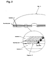
- FIG. 2 is a view of an optical disc, showing a cross sectional portion thereof in enlarged detail.
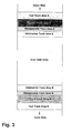
- FIG. 3 is a diagram showing how different regions of the disc are allocated in an optical disc used in accordance with the present invention.
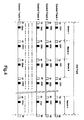
- FIG. 4 is a schematic drawing of a control track format.
- FIG. 5 shows the recording conditions for an erasable type disc, wherein FIG. 5(a) shows an optically modulated laser power waveform, FIG. 5(b) shows a schematic drawing of a track prior to recording, FIG. 5(c) is a schematic drawing of the track after recording, and FIG. 5(d) is a playback signal waveform.
- FIG. 6 shows recording conditions for a write-once type disc wherein FIG. 6(a) shows an optically modulated laser power waveform, FIG. 6(b) is a schematic drawing of a track prior to recording, FIG. 6(c) is a schematic drawing of the track after recording, and FIG. 6(d) is a playback signal waveform.
- FIG. 7 is a block diagram of a laser power control circuit.
- FIG. 8 is a block diagram of a playback signal processing circuit.
- FIG. 9 is a block diagram of a servo circuit.
- FIG. 10 illustrates the data format of a write-once type disc wherein FIG. 10(a) is a schematic drawing of the data format, and FIG. 10 (b) illustrates the resync gate signal.
- FIG. 11 illustrates the data format of an erasable type disc wherein FIG. 11(a) is a schematic drawing of the data format and FIG. 11(b) illustrates the resync gate signal.
- FIG. 1 shows a circuit block diagram of one embodiment of an optical disc record and playback apparatus in accordance with the present invention.
- Data prepared by a host computer represented as write data WTDT1
- WTDT2 is sent to a drive controller 2.
- WTDT2 is sent to a laser power control circuit 3, which converts the data WTDT2 into a signal WTDT3 for optical modulation of a laser diode 4.
- Signal WTDT3 is then recorded on an optical disc 6 through an optical head 5.
- the disc 6 may be an erasable type disc or a write-once type disc, and is rotated, for example, at 1800 rpm by means of a disc motor 7.
- the laser light output from laser diode 4 reflected from the disc 6 passes through the optical head 5 and is received by an optical detector 8.
- the output of the optical detector 8 passes through a head amplifier 9 and is divided into a playback signal RDDT1, a focus signal F for controlling a focus servo and a tracking signal T for controlling a tracking servo.
- the playback signal RDDT 1 is converted into binary values by an analog signal processor 10, thereby becoming read data RDDT 2, which is sent to the drive controller 2.
- the read data RDDT2 is demodulated and error-corrected to become read data RDDT 3. This signal is then sent to the host computer 1, which reads the data.
- the focus signal F is converted in focus error pre-amplifier 11 to a focus error signal FE which is applied to an actuator 13 through a focus servo circuit 12, for the purpose of maintaining proper focus of the laser light on the optical disc 6.
- the tracking signal T is converted by tracking error pre-amplifier 14 to a tracking error signal TE which is applied to the actuator 13 in the optical head through a tracking servo circuit 15, for the purpose of maintaining proper tracking of the laser light with respect to the disc 6.
- Switches SW 1 and SW 2 of FIG. 1 are disc selection switches.
- an erasable mode is entered in which the record and playback apparatus is only permitted to write on an erasable type disc. In this mode, a write-once type disc can not be written on, but may only be played back.
- switch SW 2 is closed, a write-once mode is entered in which it is possible to only write on a write-once type disc. In the write-once mode, erasable type discs can not be written on, but may only be played back. If switches SW 1 and SW 2 are both closed, a multi-function mode is entered in which recording and playback are possible on both erasable type discs as well as write-once type discs.
- switches SW 1 and SW 2 are both open, a playback only mode is entered in which writing is rendered impossible and both disc types can only be played back.
- Drive controller 2 monitors the status of these switches and therefore knows whether the record and playback apparatus has been set in the erasable mode, the write-once mode, the multi-function mode, or the playback only mode.
- FIG. 2 shows a cross sectional view and an expanded view of a disc 6 which may be utilized in the record and playback apparatus in accordance with a preferred embodiment of the present invention.
- Disc 6 has a two-faced structure in which a thin film recording layer of either an erasable type or a write-once type is deposited on a substrate 16.
- a spiral-shaped track 17 is pre-grooved to a depth of ⁇ /8 (where ⁇ is the wavelength of the laser light) and a signal is recorded and reproduced along this pre-grooved track 17.
- FIG. 3 shows the allocation of regions of the discs used in accordance with a preferred embodiment of the present invention.
- the disc is divided, starting from the outer circumference thereof, into a test track area A, a control track area A, a management track area A, an alternation track area A, a user data area, an alternation track area B, a management track area B, a control track area B and a test track area B.
- the test track areas A and B are areas which permit testing of the recording and playback performance of a disc by carrying out a test write on the disc.
- the control track areas A and B are the areas which are initially read for setting the operating conditions of the record and playback apparatus.
- An example of the information stored in these control areas is shown in FIG. 4.
- a control area consists of m tracks (for example, 64 tracks), with each track divided into n sectors.
- the track A may have 17 sectors and the control track B may have 17 or 18 sectors.
- an address signal ID and control data CD as convex and concave bits on the disc substrate 16.
- the control data are identical throughout one circle of a track and as a track is updated, the control data is updated.
- the control data may designate, for example, the type of disc (i.e. whether a disc is an erasable type or a write-once type, a type exclusively for playback, or a type which includes a combination of these features).
- control data includes information about the recording and playback parameters required for operation of the disc.
- the control data area is read, thereby informing the disc controller 1 of the type of disc which is currently in use, so that the recording and playback parameters corresponding to that particular disc may be set.
- On management track areas A and a of FIG. 3 is written data which indicates the fluctuations in recording and erasing sensitivity of the disc caused by manufacturing tolerances. Specifically, the correction power required to compensate for a fluctuation is recorded therein. While discs of a particular type are nominally identical, the recording and playback sensitivities vary from disc to disc due to fluctuations in manufacturing. Therefore, if data corresponding to sensitivity fluctuations specific to each disc is recorded on that disc, the power for recording and erasing may be corrected after this data is read and processed by the record and playback apparatus. This permits each optical disc to be irradiated with optimum power to compensate for sensitivity fluctuations which arise during manufacture.
- the alternation track areas A and B are areas which may be alternatively used depending on defects in the disc.
- a write-once type disc the disc is written on only once. Since only playback is performed thereafter, most defects of the disc arise during manufacture, and the number of defects is generally small.
- an erasable type disc the same tracks are repeatedly used for recording and erasing. Gradual deterioration due to this repetitive cycling introduces defects which add to the original defects present at the time of manufacture, and consequently the number of defects increases with time. Therefore, in the case of a write-once type disc, either alternation track area A or alternation track area B is used as an alternation track area, and the other is used as a user area.
- both alternation track areas A and B are generally designated and used as alternative areas for data storage. As its name implies, the user track area is an area designated for the recording and playback of user data.
- the drive controller 2 After the drive controller 2 reads the control data and recognises whether the inserted disc is of a write-once type or an erasable type, recording and playback parameters appropriate to that type of disc are automatically set in the record and playback apparatus of the present invention.
- FIG. 5 shows the recording and playback parameters which pertain to an erasable type disc.
- an erasable type disc one may consider a phase-change erasable disc in which a reversible phase transition between an amorphous phase and a crystalline phase is utilized.
- FIG. 5(a) shows a typical laser power modulation waveform for irradiating a phase-change erasable type disc. For example, regions on the disc corresponding in position to the peak power pulses P PE may be designated as a binary "1" of user data, whereas regions corresponding to a binary "0" may be formed by irradiating the erasable disc with the bias power level P BE .
- FIG. 5(b) is a schematic representation of a track on a disc prior to recording
- FIG. 5(c) is a schematic representation of a track on a disc after recording
- FIG. 5(d) indicates the playback signal from the track.
- the laser power is generally controlled in 3 stages.
- the laser power for playback of signals recorded on the disc is at a read power level P RE , which, by way of example, is selected to be between 0.3 and 2.5 mW on the disc.
- the laser power for producing a crystalline state (the erased condition) on the disc is a bias power level P BE , which is selected, for example, to be between 3 and 20 mW on the disc.
- the laser power for producing an amorphous state (the written condition) on the disc corresponds to a peak power level P PE , which is selected, for example, to be between 10 and 40 mW on the disc.
- the bias power and the peak power levels may be varied as a function of the radial position of the laser spot on the disc. Each power level may be adjusted in such a manner that it is higher towards the outer circumference of the disc and lower towards the inner circumference thereof.
- the pulse width is generally selected to be between about 20 and 50% of the period T min , which corresponds to the maximum frequency of the recording and playback signals.
- the pulse width T PE of the peak power irradiation level P PE for an erasable type disc is selected to be small and is chosen in such a manner that thermal damage on the erasable disc is minimized.
- a playback signal from the disc is obtained by sensing the difference in reflectivity between amorphous and crystalline areas of the track, since the reflectivity of an amorphous area is generally lower than that of a crystalline area.
- the amorphous area may be designated as a binary "1" of user data. Since the binary "1" is recorded by changing from a state of high reflectivity (crystalline) to a state of lower reflectivity (amorphous), a low amplitude of the playback signal corresponds to written data in this erasable type disc.
- FIG. 6 shows the recording and playback parameters which pertain to a write-once type disc.
- a write-once type disc one may use a phase-change recording material in which a phase transition from an amorphous state to a crystal state is possible only once.
- FIG. 6(a) shows an optically modulated laser power waveform for irradiating a write-once type disc.
- recording may be performed whereby the position of the peak power pulse corresponds to a binary "1" of user data.
- FIG. 6(b) shows an unrecorded track prior to recording, which is initially prepared in the amorphous state.
- FIG. 6(c) shows the track after recording, with crystalline spots formed to correspond to the written state or binary "1" of user data.
- FIG. 6(d) shows a playback signal from the track of FIG. 6(c).
- FIG. 6(a) shows that the typical laser power parameters for a write-once disc are controlled in 3 stages.
- the laser power needed to play back a recorded signal from the disc is at a read power level P RW , which is selected to be, for example, between 0.3 and 2.5 mW on the disc.
- the bias power P BW is selected to be lower than the read power P RW (for example 0.4 mW) so that no recording results thereby.
- the laser power required to produce a crystalline state on the write-once type disc is a peak power level P PW , which is selected to be, for example, between 10 and 40 mW on a disc.
- the peak power level P PW may be varied depending on the radial position of the laser beam on the disc, and is generally adjusted so that it is higher towards the outer circumference of the disc and lower towards the inner circumference thereof.
- the pulse width T PW of the peak power level is selected to be between about 10% and 50% of the period T min which corresponds to the maximum frequency of the recording and playback signal.
- the pulse width T PW of the peak power on a write-once type disc may be selected to be relatively large in value.
- a playback signal from the write-once disc is obtained by measuring the difference in the read laser power reflected from the disc, since the reflectivity of an amorphous area is lower than that of a crystalline area.
- the amorphous area is recorded and played back to correspond to a binary "1" of user data. Since a binary "1" of user data is recorded by changing from an amorphous state of low reflectivity to a crystalline state of high reflectivity, a high amplitude of the playback signal corresponds to written data in the write-once type disc.
- FIGS. 5(a) or FIG. 6(a) If laser power parameters are selected in accordance with the criteria shown in FIGS. 5(a) or FIG. 6(a), recording and playback of information on an erasable type disc or a write-once type disc becomes possible.
- the laser power parameters are controlled by the laser power control circuit 3 of FIG. 1.
- FIG. 7 shows a more detailed preferred embodiment of the laser power control circuit 3.
- the laser diode 4 is controlled to provide the required power levels.
- a pin diode 18 is used to monitor the power output of laser diode 4.
- Signal RPC carries read power data by which the read power is determined
- signal BPC carries bias power data by which the bias power signal is determined
- signal PPC carries peak power data by which the peak power is determined.
- Signals RPC, BPC and PPC are obtained from the drive controller 2 shown in FIG. 1.
- the three power data signals RPC, BPC and PPC are respectively converted into reference voltages VR, VB and VP by digital to analog (D/A) converters 19-21.
- Each of the above-mentioned reference voltages is compared with the monitor output from the pin diode 18 in differential amplifiers 22-23 respectively, the outputs of which are sent through analog switches 25-27 to a laser drive circuit 28 which drives the laser diode 4 to output the required power level.
- Analog switch 25 is closed by a PLY signal at the time when a read power level is required;
- analog switch 26 is closed by a BIAS signal when a bias power level is required; and
- analog switch 27 is closed by a PEAK signal at the time when a peak power level is required.
- an optically modulated waveform as shown in FIG. 5(a), may be obtained by outputting a signal RPC to generate the appropriate read power level P RE (e.g. from 0.3 to 2.5 mW) needed to playback information stored on the erasable type disc; or by outputting a signal BPC to generate the required bias power level P BE for erasable type discs (e.g., from 3 to 20 mW); or by outputting a signal PPC to generate the requisite peak power level P PE for erasable type discs (e.g. from 10 to 40 mW).
- Signals RPC, BPC and PPC are provided by drive controller 2.
- an optically modulated waveform of the type shown in FIG. 6(a) can be obtained by outputting a signal RPC for generating the requisite read power level P RW (for example, from 0.3 to 2.5 mW) for playback of a write-once type disc; or by outputting a signal BPC for generating the bias power level P BW for write-once type discs (for example from 0 to 1.0 mW); or by outputting a signal PPC for generating the peak power level P PW (for example, from 10 to 40mW).
- a signal RPC for generating the requisite read power level P RW (for example, from 0.3 to 2.5 mW) for playback of a write-once type disc
- a signal BPC for generating the bias power level P BW for write-once type discs (for example from 0 to 1.0 mW)
- PPC for generating the peak power level P PW (for example, from 10 to 40mW).
- the pulse widths T PE and T PW of the peak power level for erasable type discs or write-once discs, respectively, are obtained by converting the above-mentioned write data WTDT 2 to a pulse width selected by a pulse width control circuit 29, which is then applied to the laser drive circuit 28 to provide the desired optical modulation.
- the selection of the pulse width is made in accordance with a PLS signal sent from the drive controller 2. In the case of an erasable type disc, a pulse width T PE of 30 to 130 ns is selected, whereas in the case of a write-once type disc, a pulse width T PW of 40 to 130 ns is selected.
- the laser control circuit of FIG. 7 may be incorporated in the optical disc record and playback apparatus in accordance with the present invention.
- the laser power control circuit of FIG. 7 makes it possible to set the optimum recording and reproducing parameters for each disc. Specifically, the laser power control circuit controls the switching of the laser power levels between playback, bias and peak powers, and also switches the peak power pulse width to the appropriate values, depending on the type of disc being utilized.
- FIG. 8 shows a detailed block diagram of the signal processing circuit 10 (FIG. 1) used in the optical disc recording and playback apparatus in accordance with a preferred embodiment of the present invention.
- the playback signal from an erasable type disc has a low signal amplitude indicating the presence of data (as shown in FIG. 5(d)), whereas the playback signal for a write-once type disc has a high signal amplitude indicating the presence of data (as shown in FIG. 6(d)), because the polarity of the playback signal is different for these two types of discs.
- the amplitude of the playback signal for the erasable type disc is higher. Therefore, in order to properly playback either type of disc, it is necessary to select the polarity and the amplification of the playback signal.
- a playback signal RDDT 1 from the head amplifier 9 is sent to a pre-amplifier 30.
- the pre-amplifier 30 is designed in such a manner that it may select the polarity of an amplifier contained therein as determined by a POLARITY signal sent from the drive controller 2. Additionally, an attenuation factor for the amplifier contained therein may be selected to be, for example, 0, -2, -4, -6, and 26 dB, in response to the value of an REGAIN signal. In the case where a reading of the control track indicates that the disc is an erasable type, the pre-amplifier 30 behaves as an inverting amplifier and an attenuation rate may be selected to be, for example, -4 dB. In the case where the disc being used is a write-once type, the pre-amplifier 30 acts as a non-inverting amplifier and the attenuation factor may be selected to be, for example, 0 dB.
- the selection of the polarity and attenuation factor of the pre-amplifier 30 may also be used during playback of the address signal (ID signal) of each track.
- ID signal the address signal
- the polarity and amplitude of an ID signal differs between an ID signal for a groove track 17 (shown in FIG. 2) having a depth of ⁇ /8 (where ⁇ is the laser wavelength), an ID signal for an on-land track having a depth of ⁇ /4 and a groove track of depth ⁇ /8, as used in an ordinary magneto-optical disc (MO) of the ISO (International Standard Organization).
- MO magneto-optical disc
- ISO International Standard Organization
- the above-mentioned polarity is inverted and the attenuation factor may be selected to be -6 dB.
- the gain of pre-amplifier 30 is held at -26 dB, thereby preventing the reflected light from saturating the pre-amplifier 30.
- the IDS signal is an address gate which is present only when an ID section is being played back.
- the output of pre-amplifier 30 is sent to an equalizer 31.
- the characteristics of the equalizer 31 are selected by an EQL signal so that an optimum equalizer level is selected for an erasable type disc or a write-once type disc.
- the output signal from the pre-amplifier 30 is also sent to a comparator 32.
- Comparator 32 functions to detect the presence of unrecorded section on the disc, and operates in the following manner. If a playback signal is smaller than an envelope detection level V ENV , it is judged to be an unrecorded signal level.
- the gain of an AGC circuit 33 (described more fully below) is clamped, and the data gate 39 is opened to prevent a noise signal corresponding to an unrecorded section of the disc from being output.
- the playback signal processor circuit prevents noise corresponding to an unrecorded section of the disc from being output.
- An optimum value for the signal V ENV may be selected depending on an whether the disc being utilized is an erasable type disc or a write-once type disc. For example, in the case of an erasable type disc (for which the playback signal is relatively large), the signal V ENV is set to a relatively high value. On the other hand, in the case of a write-once type disc for which the amplitude of the playback signal is relatively small, the V ENV signal is set to a lower value.
- Auto gain control (AGC) circuit 33 absorbs amplitude differences which cannot be absorbed by the pre-amplifier 30 and outputs a signal of a certain amplitude.
- Differential circuit 34 is coupled to an inversion amplifier 35, from where a pulse signal corresponding to a binary "1" of data is obtained.
- Envelope detection circuit 36 with about one half of the envelope-detected level as a threshold level, provides a gate signal to a comparator 37 for selecting data "1".
- the threshold level may be varied by applying an external V VFY voltage to the comparator 37.
- Signal V VFY is called a verify voltage, and is used to play back a signal by intentionally changing the threshold level immediately after recording of the signal, for determining whether or not the signal has been recorded in a sufficiently stable manner.
- V VFY An optimum value for this verify voltage V VFY depends upon whether the disc being played back is an erasable type disc or a write-once type disc. For example, for an erasable type disc in which unerased signals may be generated, the verify voltage V VFY may be set low in comparison with a write-once type disc. If the above-mentioned pulse signal and gate signal produce an output at AND gate 38, the signal output therefrom becomes the read data signal RDDT 2.
- the playback signal processor circuit of FIG. 8 may be used in the recording and playback apparatus in accordance with a preferred embodiment of the present invention.
- the playback signal processing circuit sets optimum playback conditions for each type of disc. Specifically, the playback signal processing circuit provides for the switching of the polarity and attenuation level of the playback signal (both data and ID signals), the detection and switching out of signals corresponding to unrecorded sections of the disc, the switching of appropriate equalizer levels, verify voltage levels, etc.
- FIG. 9 shows, in block diagram form, a preferred embodiment of a servo circuit for providing focusing and tracking control in the record and playback apparatus of the present invention.
- Focus signals F+ and F- and tracking signals T+ and T- are obtained from the optical detector 8 in the optical head 5 (see FIG. 1).
- the above-mentioned signals are respectively input to servo amplifiers 40-43.
- the gain of each of the servo amplifiers 40-43 may be switched by an ERASE signal obtained from the drive controller 2.
- the optical modulation waveforms for recording are different for an erasable type disc and for a write-once type disc. Therefore, the reflected light levels at the time of recording, and in particular, the signal levels of the F+, and F- and T+ and T- signals differ greatly depending upon whether an erasable type disc or a write-once type disc is being utilized.
- the bias power level P BE is 10 mW and the peak power level P PE is 20 mW for an erasable type disc
- the bias power level P BW and the peak power level P PW are respectively selected to be 0.4 mW and 18 mW for a write-once type disc. If, for simplicity, we assume that the pulse width of the peak power level is 33% of the period of the maximum recording frequency signal for either of the two types of discs, then the average recording power for an erasable disc is about 13.2 mW, which is about 8.8 times that of the read power in the case of an erasable type disc.
- the average recording power is about 6.2 mW, or about 4 times that of the read power.
- the factor of 4 in the case of a write-once type disc can be absorbed in an AGC circuit.
- the factor of 8.8 for an erasable type disc is too large to be absorbed by the AGC circuit. Therefore, in the servo circuit used in the record and playback apparatus of the present invention, the gain of each of the above-mentioned servo amplifiers 40-43 is reduced by about 1/2 to 1/8 by an ERASE signal only when recording on an erasable type disc, so that the signals will fall within the operating range of an AGC circuit.
- Servo amplifiers 40-43 are coupled as shown in FIG. 9 to differential amplifiers 44 and 45 and to summing amplifier 46.
- Automatic gain control (AGC) circuits 47, 48 maintain the output of each of the above-mentioned differential amplifiers at a constant level by dividing the signal output from the differential amplifiers 44 and 45 by a signal AS output from the summing amplifier 46.
- the output signal from the AGC circuit 47 provides a focus error signal FE which is sent to the focus servo circuit through an analog switch 49.
- Analog switch 49 is used during adjustment of the focus servo. To adjust the focus servo, an actuator 13 in the optical head is moved up and down in response to a focus on signal FCON.
- the analog switch 49 is closed by an output signal from a comparator 50 when the output from the differential amplifier 44 exceeds the threshold level V F of the comparator 50, thereby providing adjustment of the focus servo.
- the reflectivity of an erasable type disc is different from that of a write-once type disc, with the reflectivity being higher for an erasable type disc as compared to a write-once type disc. Therefore, the above-mentioned comparator level V F is different for each type of disc. For example, the level V F is set high for an erasable type disc and low for a write-once type disc.
- AGC circuit 48 generates a tracking error signal TE which is provided to a tracking servo circuit.
- the servo circuit of FIG. 9 incorporated in the optical disc record and playback apparatus of the present invention, after a determination is made as to whether an erasable type disc or a write-once type disc is being utilized, it is possible to set the optimum focus and tracking conditions for each disc. Specifically, the servo circuit of FIG. 9 provides for the adjustment of the amplification of the servo amplifiers at the time of recording, and for the adjustment of the comparator levels which control the output of the focus servo.
- FIG. 10(a) is one example of a data format recorded on a write-once type disc.
- Address signals ID 1 and ID2 are written on the disc in advance, and t 1 sec after ID 1, recording starts with a SYNC 1 signal.
- SYNC 1 and SYNC 2 are identical signals, which are used for adjusting a phase locked loop (PLL) circuit during playback.
- PLL phase locked loop
- the highest frequency signals are recorded, with the length of the SYNC 1 signal being, for example, 12 bytes.
- Data mark 1 (DM1) is a signal for identifying the beginning of the DATA 1 signal.
- a signal of the lowest frequency is recorded to represent DM1.
- the signals DATA 1 to DATA m represent m blocks of user data, and at the beginning of each of these respective data blocks there are provided RESYNC signals 1 through m which identify the beginning of each of the data blocks.
- FIG. 10(b) shows resync gate signals for selecting the above-mentioned RESYNC signals and their corresponding data blocks during playback operation.
- the gate signals have slightly larger widths (t 2 ) than the widths of the RESYNC signals.
- FIG. 11(a) shows one example of a data format recorded on an erasable type disc.
- Address signals ID 1 and ID 2 are written on the disc in advance, and recording starts with the SYNC 1 signal.
- the recording start time for an erasable type disc is different from that of a write-once type disc. Since the same track is used repeatedly for recording the case of an erasable type disc, deterioration of the recording layer on which the same data patterns (i.e. the SYNC 1, SYNC 2, DM 1 and RESYNC 1 through m signals) are recorded is accelerated. To reduce deterioration, the recording start positions are intentionally changed in a random manner so that the same signals are not repeatedly recorded on the same positions of the recording layer, thereby preventing the film from deteriorating.
- the starting position for recording the SYNC 1 signal and its contiguous data block DATA 1 signal is randomly changed to fall in an interval between t3 and t3 + ⁇ t, where ⁇ t is randomly determined.
- Other sync signals and data blocks are recorded on the disc in the same manner.
- SYNC 1 and SYNC 2 are identical signals, and, as in the case of the write-once type disc, are used for adjusting a phase locked loop (PLL) circuit during playback.
- PLL phase locked loop
- the highest frequency signals are used to record the SYNC 1 and SYNC 2 signals
- the length of the SYNC 1 signal on an erasable type disc is, for example, 20 bytes, and is longer in comparison to the length of the SYNC 1 signal (12 bytes) for a write-once type disc. This is because the deterioration due to repeated recording on the same track is taken into account for the erasable type disc.
- data mark 1 is a signal for identifying the beginning of the DATA 1 block.
- the DM1 signal is also different from the corresponding signal for a write-once type disc.
- a write-once type disc in order to distinguish the DM1 signal from the SYNC1 and SYNC2 signals, a signal of the lowest frequency is recorded.
- a pattern that makes the temperature difference at the boundary between the regions where the DM 1 and the SYNC 1 and SYNC 2 are to be recorded as small as possible (when the same track is used repeatedly for recording) is selected for the data mark (DM1) signal.
- the temperature difference at the above-mentioned boundary is large, thermal stress accumulates with repeated recordings and it is possible that the recording film may deteriorate at that boundary.
- the data mark 1 on an erasable disc use is made of a signal pattern having a high frequency which is as close as possible to the patterns of the SYNC 1 and SYNC 2 signals.
- FIG. 11(b) shows resync gate signals for selecting the RESYNC signals during playback of an erasable disc.
- the resync gate signal must follow this pattern and be as wide as t2 + k ⁇ t.
- an optimum format for each type of disc may be set and recorded.
- the data format provides for adjustment of the recording start position, adjustment of the length of the SYNC signal, and the switching of various patterns for the data mark and resync gate signals, etc., in accordance with the type of disc being utilized.
- the identification of an erasable type disc or a write-once type disc is made by reading the control track data.
Landscapes
- Physics & Mathematics (AREA)
- Optics & Photonics (AREA)
- Engineering & Computer Science (AREA)
- Signal Processing (AREA)
- Optical Recording Or Reproduction (AREA)
- Signal Processing For Digital Recording And Reproducing (AREA)
- Moving Of The Head For Recording And Reproducing By Optical Means (AREA)
- Optical Head (AREA)
Claims (8)
- Vorrichtung, die einen Laser zur optischen Aufzeichnung und Wiedergabe von Informationen verwendet, die auf einer Platte kodiert sind, die entweder ein löschbarer Platten-Typ oder ein einmal beschreibbarer Platten-Typ ist, wobei es die Platten-Typen erforderlich machen, daß die Vorrichtung auf verschiedene Betriebsparameter eingestellt wird, wobei die Vorrichtung aufweist:(a) eine Einrichtung, um zu erkennen, welche der Platten-Typen darin eingesetzt ist, dadurch gekennzeichnet, daß die Vorrichtung außerdem aufweist:(b) eine Datenformateinrichtung, die zufällig die Startposition zum Aufzeichnen der Informationen verändert, wenn die in die Vorrichtung eingesetzte Platte als eine löschbare Platte erkannt wird.
- Vorrichtung nach Anspruch 1, bei der die Einrichtung zum Erkennen des Plattentyps eine Einrichtung zum Verarbeiten von Erkennungsdaten aufweist, die auf einer Steuerspur der Platte gespeichert sind.
- Vorrichtung nach Anspruch 1, bei der die Einrichtung zum Erkennen des Plattentyps das Vorhandensein einer Erkennungsmarkierung auf einem Gehäuse aufweist, in der die Platte enthalten ist.
- Vorrichtung nach Anspruch 1, bei der die Datenformateinrichtung ein Datenformat vorsieht, in dem die aufgezeichneten Informationen in einer Anzahl von Datenblöcken kodiert sind, die Resync-Signale enthalten, durch die die einzelnen Blöcke voneinander getrennt sind, wobei die Datenformateinrichtung ein Gate-Signal zum Auswählen der Resync-Signale setzt, wobei die Breite des Gate-Signals entsprechend dem erkannten Platten-Typ eingestellt wird.
- Vorrichtung nach Anspruch 4, bei der die Breite des Gate-Signals zum Auswählen der Resync-Signale für einen löschbaren Platten-Typ breiter eingestellt ist als für einen einmal beschreibbaren Platten-Typ.
- Vorrichtung nach Anspruch 4, bei der das Datenformat außerdem Sync-Signale am Anfang der Datenblöcke enthält und die Datenformateinrichtung die Länge von zumindest einem der Sync-Signale für einen löschbaren Platten-Typ größer einstellt als für einen einmal beschreibbaren Platten-Typ.
- Vorrichtung nach Anspruch 4, bei der das Datenformat außerdem ein Datenmarkierungs-Signal am Anfang der Datenblöcke enthält, um die Wiedergabe davon zu synchronisieren, und bei der die Datenformateinrichtung die Durchschnittsfrequenz des Datenmarkierungs-Signal für einen löschbaren Platten-Typ höher einstellt als für einen einmal beschreibbaren Platten-Typ.
- Vorrichtung nach Anspruch 4, bei der die Größe von anderen Bereichen auf der Platte zum Aufzeichnen von Benutzerdaten bei einem löschbaren Platten-Typ größer eingestellt wird als bei einem einmal beschreibbaren Platten-Typ.
Applications Claiming Priority (2)
| Application Number | Priority Date | Filing Date | Title |
|---|---|---|---|
| JP2202181A JP2809835B2 (ja) | 1990-07-30 | 1990-07-30 | 光ディスク装置および光ディスク |
| JP202181/90 | 1990-07-30 |
Publications (2)
| Publication Number | Publication Date |
|---|---|
| EP0469727A1 EP0469727A1 (de) | 1992-02-05 |
| EP0469727B1 true EP0469727B1 (de) | 1999-04-07 |
Family
ID=16453304
Family Applications (1)
| Application Number | Title | Priority Date | Filing Date |
|---|---|---|---|
| EP91306062A Expired - Lifetime EP0469727B1 (de) | 1990-07-30 | 1991-07-03 | Gerät zum Aufzeichnen und Wiedergeben von optischen Platten |
Country Status (4)
| Country | Link |
|---|---|
| US (1) | US5544137A (de) |
| EP (1) | EP0469727B1 (de) |
| JP (1) | JP2809835B2 (de) |
| DE (1) | DE69131086T2 (de) |
Cited By (1)
| Publication number | Priority date | Publication date | Assignee | Title |
|---|---|---|---|---|
| US8310907B2 (en) | 2003-07-07 | 2012-11-13 | Lg Electronics Inc. | Recording medium, method of configuring control information thereof, recording and/or reproducing method using the same, and apparatus thereof |
Families Citing this family (58)
| Publication number | Priority date | Publication date | Assignee | Title |
|---|---|---|---|---|
| JP3368908B2 (ja) * | 1991-07-24 | 2003-01-20 | 松下電器産業株式会社 | 光磁気ディスク記録再生装置 |
| DE69317831T2 (de) * | 1992-08-04 | 1998-08-06 | Sony Corp | Wiedergabegerät |
| JPH06150357A (ja) * | 1992-11-04 | 1994-05-31 | Pioneer Electron Corp | 光ディスク記録再生装置 |
| US5355356A (en) * | 1993-05-19 | 1994-10-11 | Maxoptix Corporation | Charge pump for restoring DC in an optical recording read channel |
| EP0708962B1 (de) * | 1993-06-11 | 1999-10-20 | Kabushiki Kaisha Toshiba | Optiches aufzeichnungsmedium und speichersystem |
| US5502702A (en) * | 1993-08-09 | 1996-03-26 | Yamaha Corporation | Optical disc recording device using basic recording information and projection time control |
| US5418767A (en) * | 1993-10-28 | 1995-05-23 | International Business Machines Corporation | Detection of overusage of spare sectors in an optical disk |
| TW249856B (en) * | 1993-11-12 | 1995-06-21 | Sony Corp | Control apparatus for recording medium |
| JP2944411B2 (ja) * | 1994-03-22 | 1999-09-06 | 三洋電機株式会社 | ピット/グルーブ判別回路 |
| US5568461A (en) * | 1994-04-20 | 1996-10-22 | Matsushita Electric Industrial Co., Ltd. | Optical information recording and reproducing apparatus |
| EP0737969B1 (de) * | 1995-04-10 | 2001-09-05 | Nikon Corporation | Optische Aufzeichnungsverfahren und optisches Aufzeichnungsgerät |
| US5726954A (en) * | 1995-04-10 | 1998-03-10 | Nikon Corporation | Optical recording method and apparatus |
| US5737301A (en) * | 1995-06-01 | 1998-04-07 | Hitachi, Ltd. | Laser control for setting average recording power of "1" equal to average recording power of "0" |
| US5793723A (en) * | 1995-06-14 | 1998-08-11 | Nikon Corporation | Method and a system for adjusting optical recording device involving an optical recording medium of non-uniform heat characteristics |
| JPH097178A (ja) * | 1995-06-15 | 1997-01-10 | Nikon Corp | 光ディスクの再生方法、再生装置及び光ディスク |
| JPH0916964A (ja) * | 1995-06-26 | 1997-01-17 | Pioneer Electron Corp | 光学式記録媒体および光ビームの供給パワー設定方法 |
| JP3284296B2 (ja) * | 1995-06-27 | 2002-05-20 | 富士通株式会社 | 光記録媒体及びその記録再生方法 |
| JPH0927154A (ja) * | 1995-07-10 | 1997-01-28 | Fujitsu Ltd | 光磁気ディスク装置 |
| JP3707833B2 (ja) * | 1995-08-10 | 2005-10-19 | 株式会社東芝 | 光ディスク装置 |
| EP0787342B1 (de) * | 1995-08-23 | 2005-05-18 | Koninklijke Philips Electronics N.V. | Aufzeichnungsträgerlesegerät mit diskriminierungsmitteln zur ermittlung des informationsträgertyps |
| JP4086913B2 (ja) * | 1995-10-09 | 2008-05-14 | 松下電器産業株式会社 | 光ディスクおよび光ディスクの再生装置 |
| JP3123591B2 (ja) * | 1995-12-20 | 2001-01-15 | 富士通株式会社 | 光ディスク装置 |
| US5886972A (en) * | 1996-01-03 | 1999-03-23 | Motorola | Recording information in a phase change optical medium with a vertical cavity surface emitting laser |
| JPH09330519A (ja) * | 1996-06-10 | 1997-12-22 | Hitachi Ltd | 光ディスク記録再生装置 |
| JPH103667A (ja) * | 1996-06-13 | 1998-01-06 | Sony Corp | 記録再生装置および方法、並びにディスク |
| US5978322A (en) * | 1996-07-30 | 1999-11-02 | Kabushiki Kaisha Toshiba | Optical recording medium having a parameter for identifying the format of data and a reproducing device thereof |
| JP3845849B2 (ja) * | 1996-10-18 | 2006-11-15 | ソニー株式会社 | 記録装置および記録方法、並びに記録媒体 |
| US7123563B2 (en) * | 1996-12-06 | 2006-10-17 | Koninklijke Philips Electronics N.V. | Optical recording method and apparatus using this method |
| RU2214629C2 (ru) * | 1996-12-24 | 2003-10-20 | Конинклейке Филипс Электроникс Н.В. | Способ оптической записи и устройство, использующее этот способ |
| US5991251A (en) * | 1997-03-11 | 1999-11-23 | Ricoh Company, Ltd. | Method and apparatus for changing laser beam power of an optical storage device for various types of compact disks |
| JP4144054B2 (ja) * | 1997-07-24 | 2008-09-03 | ソニー株式会社 | 光ディスクの記録方法 |
| JP3546654B2 (ja) | 1997-08-07 | 2004-07-28 | 株式会社日立製作所 | 情報記録装置及び情報記録方法 |
| US6343062B1 (en) * | 1997-09-26 | 2002-01-29 | Matsushita Electric Industrial Co., Ltd | Optical disk device and optical disk for recording and reproducing high-density signals |
| DE69931150T2 (de) | 1998-11-06 | 2007-03-01 | Matsushita Electric Industrial Co., Ltd., Kadoma | Verfahren und vorrichtung zur feststellung von bedingungen auf einem aufzeichnungspuls einer optischen platte |
| JP2000207743A (ja) * | 1999-01-13 | 2000-07-28 | Taiyo Yuden Co Ltd | 光情報記録方法及びその装置 |
| KR100339478B1 (ko) * | 1999-09-18 | 2002-05-31 | 구자홍 | 광 기록매체의 최적 기록장치 및 기록방법 |
| US6658198B1 (en) * | 1999-11-04 | 2003-12-02 | Thomson Licensing S.A. | Precessed recording for rewritable disk medium |
| JP2001155341A (ja) * | 1999-11-24 | 2001-06-08 | Sanyo Electric Co Ltd | ディスク記録装置 |
| WO2001054123A1 (en) * | 2000-01-21 | 2001-07-26 | Sony Corporation | Optical disk discriminating method and optical disk reproducing method and optical disk device |
| JP2001283443A (ja) * | 2000-03-31 | 2001-10-12 | Sony Corp | 光記録媒体、光記録方法、光再生方法、および光記録再生装置 |
| JP2002056531A (ja) | 2000-08-14 | 2002-02-22 | Ricoh Co Ltd | 光ディスク情報記録方法および記録媒体 |
| JP4595182B2 (ja) * | 2000-09-07 | 2010-12-08 | ソニー株式会社 | 情報記録装置、情報再生装置、情報記録方法、情報再生方法、および情報記録媒体、並びにプログラム提供媒体 |
| JP4419041B2 (ja) * | 2001-06-19 | 2010-02-24 | ソニー株式会社 | 光信号記録装置及び光信号記録方法 |
| JP3846249B2 (ja) * | 2001-09-28 | 2006-11-15 | ヤマハ株式会社 | 光ディスク記録装置 |
| US6774486B2 (en) * | 2001-10-10 | 2004-08-10 | Micron Technology, Inc. | Circuit boards containing vias and methods for producing same |
| JP3780910B2 (ja) * | 2001-11-14 | 2006-05-31 | 株式会社日立製作所 | 光ディスク録画装置 |
| JP2003203339A (ja) * | 2001-12-28 | 2003-07-18 | Tdk Corp | 追記型光記録媒体の記録方法及び追記型光記録媒体 |
| US7369470B2 (en) | 2002-05-20 | 2008-05-06 | Samsung Electronics Co., Ltd. | Method of recording erase pattern information on an optical recording medium, erasing information on the optical recording medium based on the erase pattern information, and optical recording medium therefor |
| US8018817B2 (en) | 2002-05-20 | 2011-09-13 | Samsung Electronics Co., Ltd. | Method of recording erase pattern information on an optical recording medium, erasing information on the optical recording medium based on the erase pattern information, and optical recording medium therefor |
| JP4342930B2 (ja) * | 2003-12-25 | 2009-10-14 | 株式会社東芝 | 光ディスク装置及びその制御方法及び記録媒体 |
| US7567266B2 (en) | 2004-04-30 | 2009-07-28 | Hewlett-Packard Development Company, L.P. | Media labeling system |
| KR100667758B1 (ko) | 2004-07-30 | 2007-01-11 | 삼성전자주식회사 | 정보 저장 매체, 기록/재생 장치 및 기록/재생 방법 |
| US20060250912A1 (en) * | 2005-05-09 | 2006-11-09 | Pratt Thomas L | System and method for multi-laser optical medium |
| TWI263208B (en) * | 2005-07-08 | 2006-10-01 | Lite On Technology Corp | Method for backuping data on an optical storage medium |
| US20100027396A1 (en) * | 2006-01-19 | 2010-02-04 | Junichi Minamino | Drop-out detecting circuit and optical disc device |
| JP4997211B2 (ja) * | 2008-10-23 | 2012-08-08 | 株式会社日立製作所 | 光ディスク、光ディスク記録方法及び装置、光ディスク再生方法及び装置 |
| EP2187393A1 (de) * | 2008-11-13 | 2010-05-19 | Thomson Licensing | Optisches Aufzeichnungsmedium mit einmal- und wiederbeschreibbaren Eigenschaften |
| JP2009283121A (ja) * | 2009-06-05 | 2009-12-03 | Hitachi Ltd | 映像情報記録装置 |
Citations (2)
| Publication number | Priority date | Publication date | Assignee | Title |
|---|---|---|---|---|
| FR2575857A1 (fr) * | 1984-11-29 | 1986-07-11 | Canon Kk | Appareil de stockage optique d'informations |
| DE3830745A1 (de) * | 1987-09-09 | 1989-03-30 | Toshiba Kk | Verfahren und vorrichtung fuer optische datenaufzeichnung/wiedergabe |
Family Cites Families (16)
| Publication number | Priority date | Publication date | Assignee | Title |
|---|---|---|---|---|
| JPS606923Y2 (ja) * | 1980-07-31 | 1985-03-07 | 日本ビクター株式会社 | 円盤状情報記録媒体収納ケ−ス |
| JPS5733441A (en) * | 1980-08-07 | 1982-02-23 | Matsushita Electric Ind Co Ltd | Optical information recorder and reproducer |
| JPS6168296A (ja) * | 1984-09-13 | 1986-04-08 | Matsushita Electric Ind Co Ltd | 光学情報記緑部材 |
| DE3601265A1 (de) * | 1985-01-18 | 1986-07-24 | Kabushiki Kaisha Toshiba, Kawasaki, Kanagawa | Optisches system fuer informationsaufzeichnung |
| JPS61170929A (ja) * | 1985-01-23 | 1986-08-01 | Matsushita Electric Ind Co Ltd | 光情報記録再生装置 |
| JPS61177642A (ja) * | 1985-01-31 | 1986-08-09 | Olympus Optical Co Ltd | 光学的情報記録再生装置 |
| JPH0756708B2 (ja) * | 1985-04-19 | 1995-06-14 | 三洋電機株式会社 | 光磁気ディスクとその記録装置 |
| JPS61280032A (ja) * | 1985-06-04 | 1986-12-10 | Matsushita Electric Ind Co Ltd | 光学式記録再生装置 |
| JPH07111782B2 (ja) * | 1986-08-13 | 1995-11-29 | ソニー株式会社 | 光デイスクの記録再生装置 |
| DE3732874A1 (de) * | 1987-09-30 | 1989-04-20 | Thomson Brandt Gmbh | Optische abtastvorrichtung |
| JPS63109366U (de) * | 1986-12-27 | 1988-07-14 | ||
| NL8800223A (nl) * | 1987-04-21 | 1988-11-16 | Philips Nv | Systeem voor het registreren van een informatiesignaal, alsmede een registratiedrager en registratieinrichting voor toepassing in het systeem. |
| JP2553603B2 (ja) * | 1987-12-25 | 1996-11-13 | 松下電送株式会社 | 光ディスク記録再生装置 |
| NL9000328A (nl) * | 1989-06-23 | 1991-01-16 | Philips Nv | Werkwijze en inrichting voor het aanbrengen van informatiepatronen op een registratiedrager. |
| US5070495A (en) * | 1989-04-12 | 1991-12-03 | International Business Machines Corporation | Write calibration for magnetooptic disk recorders |
| NL9000327A (nl) * | 1990-02-12 | 1991-09-02 | Philips Nv | Informatieoptekeninrichting. |
-
1990
- 1990-07-30 JP JP2202181A patent/JP2809835B2/ja not_active Expired - Lifetime
-
1991
- 1991-07-03 EP EP91306062A patent/EP0469727B1/de not_active Expired - Lifetime
- 1991-07-03 DE DE69131086T patent/DE69131086T2/de not_active Expired - Lifetime
-
1993
- 1993-06-21 US US08/080,583 patent/US5544137A/en not_active Expired - Lifetime
Patent Citations (2)
| Publication number | Priority date | Publication date | Assignee | Title |
|---|---|---|---|---|
| FR2575857A1 (fr) * | 1984-11-29 | 1986-07-11 | Canon Kk | Appareil de stockage optique d'informations |
| DE3830745A1 (de) * | 1987-09-09 | 1989-03-30 | Toshiba Kk | Verfahren und vorrichtung fuer optische datenaufzeichnung/wiedergabe |
Cited By (1)
| Publication number | Priority date | Publication date | Assignee | Title |
|---|---|---|---|---|
| US8310907B2 (en) | 2003-07-07 | 2012-11-13 | Lg Electronics Inc. | Recording medium, method of configuring control information thereof, recording and/or reproducing method using the same, and apparatus thereof |
Also Published As
| Publication number | Publication date |
|---|---|
| US5544137A (en) | 1996-08-06 |
| EP0469727A1 (de) | 1992-02-05 |
| DE69131086T2 (de) | 1999-08-12 |
| JP2809835B2 (ja) | 1998-10-15 |
| DE69131086D1 (de) | 1999-05-12 |
| JPH0487029A (ja) | 1992-03-19 |
Similar Documents
| Publication | Publication Date | Title |
|---|---|---|
| EP0469727B1 (de) | Gerät zum Aufzeichnen und Wiedergeben von optischen Platten | |
| KR940002000B1 (ko) | 광디스크기록/재생장치 및 그 제어방법 | |
| USRE41415E1 (en) | Optical disc including a plurality of data layers | |
| EP1308942B1 (de) | Optische Platte, entsprechendes Gerät und verfahren | |
| KR100400436B1 (ko) | 광학적 정보 기록매체 및 이에 테스트 신호를 기록하는광학적 정보 기록장치 및 방법 | |
| KR100649065B1 (ko) | 광 디스크, 광 디스크 장치, 광 디스크 기록 및 재생방법, 그리고 bca 코드 기록 방법 및 장치 | |
| US5463600A (en) | Magneto-optical recording system using recording waveform having a plurality of power levels providing high recording density | |
| JPH04212720A (ja) | 光学情報記録部材の記録方法 | |
| JP2004342271A (ja) | レーザパワー制御装置と情報記録装置と光ディスク装置とレーザ光源駆動電流値決定方法と情報記録方法と光ディスク記録方法 | |
| CA2023960C (en) | Optical disc recording apparatus | |
| RU2314579C2 (ru) | Оптический записывающий носитель данных, способ записи/воспроизведения данных на/с оптического записывающего носителя данных и устройство для записи/воспроизведения данных на/с оптического записывающего носителя данных | |
| JP2007335075A (ja) | 光記録担体記録方法及び記録装置 | |
| JPH06176368A (ja) | 光ディスクおよびその記録方法と装置 | |
| JP2605421B2 (ja) | 光ディスク記録装置 | |
| JPH03116442A (ja) | 光ディスク装置および光ディスク | |
| JPH06295439A (ja) | 光記録の記録方法 | |
| JPH097178A (ja) | 光ディスクの再生方法、再生装置及び光ディスク | |
| KR100246763B1 (ko) | 광디스크의 데이터 기록 장치 및 방법 | |
| JP2000036115A (ja) | 光記録の記録方法 | |
| JPH0991704A (ja) | 情報記録再生装置 | |
| KR100765779B1 (ko) | 기록/재생 방법 | |
| JPH05182220A (ja) | 光ディスク記録装置 | |
| JP2001034943A (ja) | ディスクドライブ装置 | |
| JPH01303627A (ja) | 光ディスク装置 | |
| JP2001067671A (ja) | 光ディスク装置 |
Legal Events
| Date | Code | Title | Description |
|---|---|---|---|
| PUAI | Public reference made under article 153(3) epc to a published international application that has entered the european phase |
Free format text: ORIGINAL CODE: 0009012 |
|
| AK | Designated contracting states |
Kind code of ref document: A1 Designated state(s): DE FR GB |
|
| 17P | Request for examination filed |
Effective date: 19920216 |
|
| 17Q | First examination report despatched |
Effective date: 19941004 |
|
| GRAG | Despatch of communication of intention to grant |
Free format text: ORIGINAL CODE: EPIDOS AGRA |
|
| GRAG | Despatch of communication of intention to grant |
Free format text: ORIGINAL CODE: EPIDOS AGRA |
|
| GRAH | Despatch of communication of intention to grant a patent |
Free format text: ORIGINAL CODE: EPIDOS IGRA |
|
| GRAH | Despatch of communication of intention to grant a patent |
Free format text: ORIGINAL CODE: EPIDOS IGRA |
|
| GRAA | (expected) grant |
Free format text: ORIGINAL CODE: 0009210 |
|
| AK | Designated contracting states |
Kind code of ref document: B1 Designated state(s): DE FR GB |
|
| REF | Corresponds to: |
Ref document number: 69131086 Country of ref document: DE Date of ref document: 19990512 |
|
| ET | Fr: translation filed | ||
| PLBE | No opposition filed within time limit |
Free format text: ORIGINAL CODE: 0009261 |
|
| STAA | Information on the status of an ep patent application or granted ep patent |
Free format text: STATUS: NO OPPOSITION FILED WITHIN TIME LIMIT |
|
| 26N | No opposition filed | ||
| REG | Reference to a national code |
Ref country code: GB Ref legal event code: IF02 |
|
| PGFP | Annual fee paid to national office [announced via postgrant information from national office to epo] |
Ref country code: GB Payment date: 20100630 Year of fee payment: 20 Ref country code: FR Payment date: 20100805 Year of fee payment: 20 Ref country code: DE Payment date: 20100630 Year of fee payment: 20 |
|
| REG | Reference to a national code |
Ref country code: DE Ref legal event code: R071 Ref document number: 69131086 Country of ref document: DE |
|
| REG | Reference to a national code |
Ref country code: DE Ref legal event code: R071 Ref document number: 69131086 Country of ref document: DE |
|
| REG | Reference to a national code |
Ref country code: GB Ref legal event code: PE20 Expiry date: 20110702 |
|
| PG25 | Lapsed in a contracting state [announced via postgrant information from national office to epo] |
Ref country code: GB Free format text: LAPSE BECAUSE OF EXPIRATION OF PROTECTION Effective date: 20110702 |
|
| PG25 | Lapsed in a contracting state [announced via postgrant information from national office to epo] |
Ref country code: DE Free format text: LAPSE BECAUSE OF EXPIRATION OF PROTECTION Effective date: 20110704 |