EP0469867B1 - Seule plaque à pliage compacte, arrangement de dépliant à deux rouleaux avec la possibilité de pliage en z-forme - Google Patents
Seule plaque à pliage compacte, arrangement de dépliant à deux rouleaux avec la possibilité de pliage en z-forme Download PDFInfo
- Publication number
- EP0469867B1 EP0469867B1 EP91306990A EP91306990A EP0469867B1 EP 0469867 B1 EP0469867 B1 EP 0469867B1 EP 91306990 A EP91306990 A EP 91306990A EP 91306990 A EP91306990 A EP 91306990A EP 0469867 B1 EP0469867 B1 EP 0469867B1
- Authority
- EP
- European Patent Office
- Prior art keywords
- sheet
- fold
- chamber
- receiving means
- gate
- Prior art date
- Legal status (The legal status is an assumption and is not a legal conclusion. Google has not performed a legal analysis and makes no representation as to the accuracy of the status listed.)
- Expired - Lifetime
Links
- 230000000903 blocking effect Effects 0.000 claims description 17
- 230000003134 recirculating effect Effects 0.000 claims description 16
- 238000004891 communication Methods 0.000 claims description 9
- 238000007599 discharging Methods 0.000 claims description 2
- 230000007246 mechanism Effects 0.000 description 6
- 239000000463 material Substances 0.000 description 4
- 238000012360 testing method Methods 0.000 description 4
- 230000008901 benefit Effects 0.000 description 2
- 238000013461 design Methods 0.000 description 2
- 230000000694 effects Effects 0.000 description 2
- 238000000034 method Methods 0.000 description 2
- 229920004943 Delrin® Polymers 0.000 description 1
- 244000182067 Fraxinus ornus Species 0.000 description 1
- 230000015572 biosynthetic process Effects 0.000 description 1
- 230000015556 catabolic process Effects 0.000 description 1
- 230000001413 cellular effect Effects 0.000 description 1
- 230000008859 change Effects 0.000 description 1
- 238000010276 construction Methods 0.000 description 1
- 238000006731 degradation reaction Methods 0.000 description 1
- 238000010586 diagram Methods 0.000 description 1
- 238000003780 insertion Methods 0.000 description 1
- 230000037431 insertion Effects 0.000 description 1
- 230000002093 peripheral effect Effects 0.000 description 1
- 229920002635 polyurethane Polymers 0.000 description 1
- 239000004814 polyurethane Substances 0.000 description 1
- 230000008569 process Effects 0.000 description 1
- 238000012545 processing Methods 0.000 description 1
- 229920005604 random copolymer Polymers 0.000 description 1
- 230000004044 response Effects 0.000 description 1
- 230000007704 transition Effects 0.000 description 1
- 230000001755 vocal effect Effects 0.000 description 1
Images




Classifications
-
- B—PERFORMING OPERATIONS; TRANSPORTING
- B65—CONVEYING; PACKING; STORING; HANDLING THIN OR FILAMENTARY MATERIAL
- B65H—HANDLING THIN OR FILAMENTARY MATERIAL, e.g. SHEETS, WEBS, CABLES
- B65H45/00—Folding thin material
- B65H45/12—Folding articles or webs with application of pressure to define or form crease lines
- B65H45/14—Buckling folders
- B65H45/142—Pocket-type folders
- B65H45/144—Pockets or stops therefor
-
- B—PERFORMING OPERATIONS; TRANSPORTING
- B65—CONVEYING; PACKING; STORING; HANDLING THIN OR FILAMENTARY MATERIAL
- B65H—HANDLING THIN OR FILAMENTARY MATERIAL, e.g. SHEETS, WEBS, CABLES
- B65H45/00—Folding thin material
- B65H45/12—Folding articles or webs with application of pressure to define or form crease lines
- B65H45/14—Buckling folders
- B65H45/142—Pocket-type folders
- B65H45/144—Pockets or stops therefor
- B65H45/145—Pockets or stops therefor circular pockets
-
- B—PERFORMING OPERATIONS; TRANSPORTING
- B65—CONVEYING; PACKING; STORING; HANDLING THIN OR FILAMENTARY MATERIAL
- B65H—HANDLING THIN OR FILAMENTARY MATERIAL, e.g. SHEETS, WEBS, CABLES
- B65H45/00—Folding thin material
- B65H45/12—Folding articles or webs with application of pressure to define or form crease lines
- B65H45/14—Buckling folders
- B65H45/142—Pocket-type folders
- B65H45/148—Pocket-type folders diverters therefor
Definitions
- the present invention involves devices for folding sheets of paper, such as documents, and in particular to devices capable of producing two or more folds in a sheet of paper.
- buckle folders function by driving a sheet of paper S with drive rollers 2,4 through a fold chamber 8 against a stop 10, and allowing a controlled buckle to form within an appropriately designed set of baffles.
- This buckle is drawn into a nip by a pair of fold rollers 4,6.
- These rollers usually contact the sheet along most of its width and have a high normal force to insure a tight fold.
- Knife folders as shown in Figure 1B, work by registering one or more sheets S adjacent a pair of fold rollers 4,6 by contacting an edge of the sheet S against a stop 10 and then deflecting the sheet(s) S into the fold nip using a moving "knife edged" bar 12 which is moved in the direction K as shown in Figure 1B.
- Knife folders have been commonly used to perform single folds on saddle stitched sets of paper, and buckle folders are often designed with two or more fold stations placed sequentially to perform more complex folds.
- Two commonly used complex folds include "letter folds", in which 21.6 x 27.9 cm (8.5 x 11 inch) or "letter" size sheets are folded twice as shown in Figure 2A.
- These folders are often used in conjunction with direct mail systems which automatically insert the folded sheets into envelopes.
- a second common complex fold is called a "Z" fold and is usually performed on A3 or 43.2 cm (17 inch) size sheets (S'') to enable the insertion of these large sheets within a set of A4 or 21.6 x 27.9 cm (8.5 x 11 inch) size paper (S').
- this type of fold makes the use and handling of large size sheets much simpler and practical by folding them so that their outer dimensions match those of standard letter size paper.
- U. S. Patent No. 4,717,134 to Iida et al. discloses a sheet folding apparatus including a plurality of sheet processing units each having a pair of folding rollers, a deflector and a fold position controlling chamber.
- the apparatus can produce two-fold, Z-fold and reverse Z-fold sheets.
- a sheet is guided by a first sheet deflector into a first fold chamber until stopped by a stopper.
- a buckle is formed and gripped by a first roller couple to form a first fold therein.
- the sheet now having one fold is guided by a second deflector to a second fold chamber until stopped by a second stopper.
- Another buckle is formed and gripped by a second roller couple to form a second fold therein.
- the sheet is then guided by a third deflector to a third stage roller couple and transported through a third passage to an outlet.
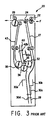
- Figure 3 illustrates a Z-fold producing sheet folder similar to that disclosed in the above-referenced U. S Patent No. 4,717,134.
- a sheet traveling along feed path F is moved into folding apparatus 20 by a pair of rollers 22.
- a first deflector 24 either allows the sheet to bypass the folding apparatus and exit through rollers 26 or is actuated to deflect the sheet through passage 27 and into fold chamber 28.
- a plurality of stoppers, or gates, 30a-d are provided in fold chamber 28 and are selectively moved into fold chamber 28 to engage a lead edge of a sheet to control the location of a first fold to be formed in the sheet. Gates 30a-d are also selectively engaged depending on the size of the sheet being folded.
- a buckle is formed and captured in the nip between rollers 32,34 to form a first fold in the sheet.
- Deflector 36 either deflects the sheet so that it passes through rollers 34,38 and into passage 43 to exit through rollers 26, or is moved out of the path of the sheet so that the sheet can enter second fold chamber 40.
- one of gates 42a,42b is moved into fold chamber 40 to stop the forward movement of the once- folded sheet therein.
- a second buckle then forms in the sheet and is captured in the nip between rollers 34,38 to form a second fold in the sheet.
- U. S Patent No. 4,905,977 to Vijuk discloses a sheet folding apparatus which places Z-folds or letter folds in one or more sheets.
- This device includes a first stopper member for stopping the passage of one or more sheets along a paper path, a knife for forcing the stopped sheet through a slot and into a first pair of fold rollers, a second stopper for stopping the once-folded sheet(s) and a second pair of fold-forming rollers for placing a second fold in the sheets.
- U. S. Patent No 4,900,391 to Mandel et al. discloses a recirculating folder for direct mail application.
- a two fold chamber, three fold roller arrangement similar to that described with reference to Figure 3 is used to place a letter fold in one or more sheets. These sheets are then recirculated to a "wait station" where they are temporarily held and then inserted into an enveloping forming sheet which is then folded and glued to form an envelope filled with insert material which is "ready-to-mail".
- U. S. Patent No. 4,518,380 to Shimizu et al. discloses a paper folding device capable of placing only a single fold in a sheet of paper.
- U. S. Patent No. 4,586,704 to Lehmann et al. discloses a folding machine for placing two folds in a sheet.
- the machine of Lehmann et al. includes two folding pockets and at least two pairs of folding cylinders to place two folds in a sheet of paper.
- U. S. Patent No. 4,455,081 to Yoshimura et al. discloses an apparatus for placing a single fold in sheets of paper.
- U. S. Patent No 3,804,399 to Rupp discloses a sheet folding apparatus which includes two fold plates and at least three fold rollers to form two folds in a sheet.
- DE-A-2,034,460 describes a folding device comprising several fold producing rollers for making several folds in a sheet.
- the disclosed apparatus may be readily operated and controlled in a conventional manner with conventional control systems.
- control systems for various prior art copiers with document handlers including sheet detecting switches, sensors, etc., are disclosed in U.S. Patent Nos.: 4,054,380; 4,062,061; 4,076,408; 4,078,787; 4,099,860; 4,125,325; 4,132,401; 4,144,550; 4,158,500; 4,176,945; 4,179,215; 4,229,101; 4,278,344; 4,284,270, and 4,475,156. It is well known in general, and preferable, to program and execute such control functions and logic with conventional software instructions for conventional microprocessors.
- the present invention provides a device for forming one or more folds in a sheet, comprising:
- the receiving means may be a chamber having at least one gate therein for blocking passage of the sheet through said chamber.
- the fold gate may be movable into and out of said chamber for alternately blocking said chamber and opening said chamber, and the outlet of the device may be attached to said receiving means downstream of said at least one gate relative to a sheet feeding direction.
- the device may further include gating means, attached to said gate, for moving said gate into and out of said chamber.
- the said gating means may be a solenoid.
- each gate When the receiving means is a chamber having a plurality of gates spaced along the chamber, each gate may be selectively movable into and out of said chamber for blocking and opening a portion of the chamber, and gating menas may be provided for selectively moving said plurality of gates into and out of said chamber based on the size of the sheet and placement of the fold in the sheet.
- the outlet of the apparatus may be attached to said chamber downstream of said plurality of gates relative to a sheet feeding direction.
- the recirculating means is a recirculation passage extending around a portion of a circumference of one of said fold producing rollers.
- the outlet of the device may be in communication with the recirculation passage, and the device may further comprise an outlet gate located between said outlet and said recirculation passage, said outlet gate being movable between a first position where it blocks access to said outlet from said recirculation passage and a second position where it extends into said recirculation passage to direct sheets to said outlet.
- the present invention further provides a sheet folding apparatus which includes an inlet for receiving a sheet material from outside of the sheet folding apparatus, an outlet for discharging the sheet material to outside of the sheet folding apparatus, and a folding mechanism within the apparatus for placing one or more folds in the sheet material.
- the folding mechanism includes a fold position controlling chamber having first and second ends and including at least one fold gate spaced from said first end for blocking the passage of a sheet through the fold position controlling chamber, first and second fold producing rollers contacting each other at peripheral surfaces thereof and located adjacent the first end of the fold position controlling chamber for withdrawing a sheet from the fold position controlling chamber and placing a fold therein and a recirculation passage extending around the periphery of one of the first and second fold producing rollers so that a sheet can be conveyed around the outer periphery thereof and be inserted back into the fold position controlling chamber after being withdrawn from the fold position controlling chamber by the first and second fold producing rollers.
- the once-folded sheet can then be directed to the outlet or back through the first and second fold producing rollers to place a second fold therein.
- the apparatus may include a first passage extending between said inlet and the first end of said fold position controlling chamber.
- the outlet of the apparatus may be in communication with one of said fold position controlling chamber and said recirculation passage.
- the apparatus may include a control gate located adjacent said inlet, said fold position controlling chamber and said recirculation passage for selectively directing a sheet from said inlet into said fold position controlling chamber, from said fold position controlling chamber into a nip formed between said first and second fold producing rollers, and from said recirculation passage into said fold position controlling chamber.
- the control gate may be movable between first, second and third positions, each of said positions corresponding to one of the selective directing functions of the control gate, and further comprising means for selectively moving said control gate to each of said first, second and third positions.
- the means for selectively moving said control gate may include a first solenoid, attached to said control gate through a linkage, for moving said control gate between said first and third positions when actuated and deactuated, respectively, and a second solenoid, extendable into a path of said linkage, for selectively blocking movement of said linkage between said first and third positions, to locate said control gate in said second position.
- the apparatus may further comprise a movable outlet deflector gate located between said outlet and one of said fold position controlling chamber and said recirculation passage for selectively blocking and opening communication between said outlet and one of said fold position controlling chamber and said recirculation passage; and a first gating means for moving said movable outlet deflector gate between said blocking and open positions.
- said outlet is in communication with said fold position controlling chamber and said movable outlet deflector gate also functions as one of said at least one fold gate when in the blocking position.
- said outlet is in communication with said recirculation passage and said movable outlet deflector gate is located between said outlet and said recirculation passage.
- That apparatus may further comprise a bypass deflector located between said inlet and said fold position controlling chamber and being movable between a blocking position wherein it blocks the passage of sheets from said inlet to said fold position controlling chamber and an open position wherein the passage of sheets from said inlet to said fold position controlling chamber is not blocked; and deflector moving means for moving said bypass deflector to the blocking position, said apparatus being operable in a bypass mode wherein said deflector moving means moves said bypass deflector to said blocking position and said first gating means moves said movable outlet deflector gate to said open position so that sheets bypass said fold position controlling chamber and exit said outlet without being folded and a folding mode wherein said deflector moving means moves said bypass deflector to said open position and said first gating means moves said movable outlet deflector gate to said blocking position so that sheets enter said fold position controlling chamber to be folded.
- a bypass deflector located between said inlet and said fold position controlling chamber and being movable between a blocking position wherein it blocks the passage of sheets from said in
- said inlet is arranged relative to said first and second fold producing rollers and said fold position controlling chamber so that a sheet enters said fold position controlling chamber from a first direction from said inlet and from a second direction, different from said first direction, from said recirculation passage.
- said inlet is arranged relative to said first and second fold producing rollers and said fold position controlling chamber so that a sheet enters said fold position controlling chamber from the same direction when said sheet is moved from said inlet as when said sheet is moved from said recirculation passage.
- FIG. 4 is a side view of a first embodiment of a sheet folding apparatus 50 according to the present invention.
- Sheet folding apparatus 50 includes an inlet 52 which receives a sheet being fed in feed direction F.
- a sheet can be fed to folding apparatus 50 from, for example, a copier or a printer.
- the sheet enters first passage 55 and contacts a moving gate buckle registration system 56 which deskews the sheets as they enter the folder.
- a switch 54 is used to time the actuation of gate 56.
- stop gate 56 is moved out of first passage 55, the sheet will be engaged between rollers 58 and 60 and deflected into fold position controlling chamber 64 by control gate 62.
- Control gate 62 can be moved in a controlled manner between positions A, B and C as described below.
- control gate 62 is in position A so that the sheet is directed into fold position controlling chamber 64.
- a fold plate stop 68 is positioned in chamber 64 to block the passage of the sheet therethrough. Once the lead edge of the sheet is blocked by fold plate stop 68 and control gate 62 is moved to position B, a buckle will form in the sheet and eventually be captured in the nip 72 between first and second fold producing rollers 58,70 which then place a fold in the sheet as well as withdraw the sheet from the fold position controlling chamber 64.
- a sensor 66 is provided in fold position controlling chamber 64 and detects the movement of the sheet into fold position controlling chamber 64 to signal a controller, to be described below, that control gate 62 should be moved to position B.
- the sheet is conveyed along a recirculation passage which extends around the periphery of the fold producing roller 70.
- the recirculation passage is defined by a plurality of plates 74 and also includes one or more follower rollers 76 that contact fold producing roller 70 to convey the sheet around rollers 70.
- the sheet After being conveyed around roller 70 once, the sheet is directed back into fold position controlling chamber 64 by contacting control gate 62 while in position B. After the sheet is sensed by sensor 66, control gate 62 is moved entirely out of the sheet conveying passages to position C.
- a second buckle is then formed in the sheet, which buckle is captured in nip 72 formed between first and second fold producing rollers 58,70 to place a second fold in the sheet while withdrawing it from fold position controlling chamber 64.
- Control gate 62 is then returned to position A and the sheet, after being conveyed around fold producing roller 70, is directed back into the fold position controlling chamber 64.
- fold plate stop 68 is moved out of chamber 64 to open this chamber and allow the sheet to exit folding apparatus 50.
- An extension 78 can be added to fold position controlling chamber 64 and an additional fold plate stop 80 can be added so that a sheet can optionally be folded in half by sheet folding apparatus 50.
- both fold plate stops 68 and 80 must be moved out of chamber 64 and extension 78.
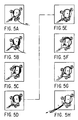
- Figures 5A-H illustrate the movement of a sheet through sheet folding apparatus 50 to place a Z-fold in the sheet. These figures also illustrate the location of control gate 62 and fold plate stop 68 during the folding process.
- Figures 6A-E illustrate the movement of a sheet through sheet folding apparatus 50 utilizing extension 78 and second fold plate stop 80 to form a half-fold in a sheet.
- the sheet enters fold position controlling chamber 64 from a first direction when entering from the inlet and from a second direction, different from the first direction, when entering from the recirculation passage.
- Control gate 62 is required in order to ensure that the sheet properly enters chamber 64 regardless of its direction of entry.
- the embodiment illustrated in Figure 4 can also be used to form letter-folds in sheets of paper by providing an additional fold plate stop 69.
- the position of this stop will depend on the size of sheet to be folded.
- stop 68 would be moved out of chamber 64 and stop 69 would be moved into and thus block passage of the sheet through chamber 64.
- a first fold would then be formed in the sheet as described above except that this fold would be produced closer to the trailing end of the sheet than when a Z-fold is produced.
- the sheet is directed back into chamber 64 except an appropriately positioned fold plate stop is now located in chamber 64 to block passage of the sheet therethrough.
- a second fold is then placed in the sheet as described above, except, due to the use of fold plate stop 69 in forming the first fold, the resulting twice-folded sheet will be in the form of a letter-fold.
- an outlet can be provided along the recirculation passage.
- a movable outlet deflector gate would be located between the outlet and the recirculation passage and would be selectively movable into the recirculation passage to deflect the folded sheet to the outlet. The provision of an outlet in the recirculation passage will be described in more detail below with reference to other embodiments. It is also understood that a sheet can be passed through folding device 50 without being folded simply by moving all of the fold plate stops, 68,69 and 80 out of chamber 64.
- Figures 7 and 8A-C illustrate the mechanism for moving the three position control gate 62 which is used to guide sheets into the fold position controlling chamber 64 from two different directions.
- the mechanism includes a first linkage 82 which is pivotally attached at first end 81 to control gate 62 at pivot point 86 and a second linkage 96 which is also pivotally attached to control gate 62 at one end and pivotally attached to a frame member at another end.
- Linkage 82 is pivotally mounted in apparatus 50 at pivot point 84.
- the linkage 82 is attached to a drive solenoid 88 through link 90 at a second end 83 thereof.
- a small solenoid 92 includes a pin 94 which acts as a stop for linkage 82, by contacting surface 97 thereof, to provide the three positions A, B and C of control gate 62.
- Pin 94 is attached to one end of a pivot arm 93 which is attached to an actuator arm of solenoid 92 and is pivotally mounted to a supporting surface 95 at an end thereof opposite from the pin 94.
- Pivot arm 93 thus supports the weight of linkage 82 and allows the full life expectancy to be realized from solenoid 92 as opposed to an arrangement where the actuator arm of solenoid 92 directly engages surface 97 of linkage 82 which results in solenoid 92 supporting the weight of linkage 82.
- FIG 9 is a side view of a second embodiment of a sheet folding apparatus 100 according to the present invention.
- Sheet folding apparatus 100 includes an inlet 152 which receives a sheet being fed in the feed direction F.
- the embodiment illustrated in Figure 9 is similar to the Figure 4 embodiment except that the sheet is fed to the fold position controlling chamber 164 from the same direction when moved from the inlet 152 and from the recirculation passage provided around fold producing roller 170.
- An advantage of this embodiment is that no control gate is required since the sheet always enters fold position controlling chamber 164 from the same direction.
- a plurality of fold plate stops 168a-d and 180 are provided in fold position controlling chamber 164 to locate a fold at a variety of locations on sheets having a variety of sizes.
- first passage 155 can include a moving gate buckle registration system and a stop gate as in the first embodiment.
- the sheet is then conveyed by rollers 160 and 170 into the fold position controlling chamber 164 until it contacts, for example, fold plate stop 180.
- a buckle then forms in the sheet which is captured in the nip formed between first and second fold producing rollers 158,170. Fold producing rollers 158,170 place a first fold in the sheet while withdrawing the sheet from fold position controlling chamber 164.
- the sheet then passes through the recirculation passage which is defined by plate(s) 174 and follower roller 176 and is reinserted into fold position controlling chamber 164.
- a second fold is then placed in the sheet as described above.
- the sheet exits folding apparatus 100 one of two ways. If the outlet passage is located on the end of fold position controlling chamber 164 opposite from the end adjacent fold producing rollers 158,170, the sheet is conveyed entirely around the recirculation passage and back into the fold position controlling chamber 164. However, after placing the desired number of folds in the sheet, all of the fold plate stops 168a-d and 180 are moved to the open position so that the folded sheet passes entirely through chamber 164 to the outlet.
- an outlet can be provided which is in communication with the recirculation passage.
- a movable outlet deflector gate 190 can be provided which, when moved into the recirculation passage, deflects the sheet out of the recirculation passage to output rollers 192.
- Output rollers 192 then conveys the sheet through outlet passage 194 to, for example, an output tray.
- Figure 10A illustrates the input and output orientations of a sheet which is Z-folded by the apparatus according to Figure 9.
- Figure 10B illustrates the input and output orientations of a sheet folded by an apparatus which is constructed as a mirror image of the Figure 9 embodiment.
- the output shown in Figure 10A would result when the apparatus is used with a printer or copier which outputs documents from its left side, whereas the Figure 10B output would result with a right side outputting printer or copier.
- Figure 11A-H illustrates the movement of a sheet S through the embodiment of Figure 9 to place a Z-fold in the sheet.
- Figure 12 is a side view of a third embodiment of a sheet folding apparatus 200 according to the present invention.
- the embodiment of Figure 12 operates in a manner similar to that of the Figure 9 embodiment, except that it is more compact and capable of inputting and outputting sheets from different directions than the Figure 9 embodiment.
- a sheet enters input 252 and, after passing through first passage 255 is directed into fold position controlling chamber 264 by rollers 260,270.
- the sheet is stopped by, for example, fold plate stop 280 and a buckle is formed and captured in the nip defined between first and second fold producing rollers 258,270.
- the sheet is folded and withdrawn from chamber 264 by fold producing rollers 258,270 and conveyed through the recirculation passage defined around the outer periphery of fold producing roller 270 with the assistance of follower roller 276.
- the once-folded sheet is inserted into chamber 264 from the recirculation passage in the same direction as when inserted from first passage 255 and is stopped by, for example, fold plate stop 268.
- the sheet is folded a second time as described above and exits folding apparatus 200 either through outlet passage 294 (through the actuation of a movable outlet deflector gate described above) or through the end of fold position controlling chamber 264 opposite from the end adjacent fold producing rollers 258,270.
- Figures 13A and 13B are similar to Figures 10A and 10B and illustrate the input and output orientations of a sheet which is conveyed through the Figure 12 device and a mirror image thereof, respectively.
- Figures 14A-H illustrate the positions of a sheet as it is conveyed through folding apparatus 200 to place a Z-fold therein.
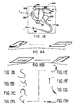
- Figure 15 is a side view of a fourth embodiment of a sheet folding apparatus 300 according to the present invention.
- An advantage of the Figure 15 embodiment is that a sheet can be passed therethrough without being folded quickly and easily by providing outlet 394 and movable outlet deflector gate 390. After entering inlet 352, a sheet passes through first passage 355 and between rollers 360 and 370. If the sheet is not to be folded, movable outlet deflector gate 390 is moved into the passage (which is the recirculation passage) around roller 370 to deflect the sheet into outlet passage 394.
- deflector gate 390 is moved to block outlet passage 394 and permit the movement of the sheet around the outer periphery of roller 370 and between rollers 370,376 to be inserted into fold position controlling chamber 364.
- the sheet is stopped by fold plate stop 380 and a buckle is formed therein and captured by the nip defined between first and second fold producing rollers 358,370.
- the sheet is folded and withdrawn from fold position controlling chamber 364 as described above. After recirculating around roller 370, the sheet is reinserted into chamber 364 and is stopped by fold plate stop 368.
- a second fold is placed in the sheet and it is then outputted from folding apparatus 300 through either outlet passage 394 or the end of fold position controlling chamber 364 which is opposite from the end adjacent the first and second fold producing rollers 358,370.
- the sheet exits along one of the paths indicated by arrows E.
- the fourth embodiment can include an additional fold plate stop for placing half-folds in sheets. It is understood that a sheet can be outputted through either of the outlets at any time (i.e., before or after being once or twice folded).
- Figures 16A and 16B illustrate input and output orientations of a sheet which is passed through the Figure 15 embodiment or a mirror image thereof to produce a Z-fold therein.
- Figures 17A-H illustrate the positions of a sheet as it is passed through the Figure 15 embodiment to place a Z-fold therein.
- a sheet folding apparatus according to the embodiment illustrated in Figure 4 (that is, the embodiment including the three position control gate 62) was built and controlled as described below.
- the three-position gate 62 must undergo three movements and the fold/exit gate (e.g., gate 68 if it is the only gate in chamber 64) must be actuated once.
- the timing for these movements was studied and optimized to give the maximum possible latitude. Solenoid response times were measured and folder operation over a large tolerance of control gate spring forces was verified. Although most testing was done with the folder operating at a paper speed of 500mm/second, the discussion below describes the necessary changes required to run at any paper velocity.
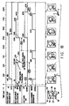
- Figure 18 illustrates the nominal timing parameters used when the Z-folder is run at 500mm/s.
- the folding apparatus was constructed according to the following parameters: the distance from sensor 66 to fold/exit gate 68 was 20mm; the diameter of first fold producing roller 58 was 35mm; the diameter of second fold producing roller 70 was 89.2mm; and the distance along the recirculation path between rollers 58 and 76 was 200mm.
- Fold producing roller 58 was made from EPDM (ethylene-propylene-diene random copolymer) having a Shore A hardness of 63 and was spring loaded against roller 70 with a total force of 27 ⁇ 4.5 lbs. although the force can be within the range between about 20 and 44 lbs.
- Fold producing roller 70 had a surface made from MCPU (Micro Cellular Polyurethane or Mearthane) having a Shore A hardness of 46.
- the follower rollers 60 and 76 were standard Delrin rollers.
- the three movements of the control gate 62, and the actuation of the fold gate stop 68 are referenced from four transitions of the fold plate sensor 66 and have been denoted as T4, T5, T6, and T7. These four timing parameters will be discussed individually.
- This time determines when the three-position gate 62 moves from its center position A, where it guides the leading edge of the sheet into the fold position controlling chamber 64, to its upper position B.
- the gate 62 When the gate 62 is in upper position B, the sheet has room to extend into the buckle chamber and be drawn into the fold nip 72. If the gate is actuated too late, the paper may begin to buckle within the chamber 64, potentially causing a jam or paper damage.
- This time determines when the drive solenoid 88 for the three-position control gate 62 is released. This occurs just prior to the formation of the second fold.
- a paper path length was chosen that results in the trail edge of a folded sheet leaving the area below control gate 62 just before its lead edge contacts the fold plate stop 68.
- the geometry is utilize to time the downward motion of control gate 62 by releasing the gate onto the trail edge of the sheet as it exits fold position control chamber 64. The gate 62 then drops when the trail edge passes the gate. If it is not desired to contact the trail edge of the sheet with control gate 62, it would be a simple design change to increase the large fold roll 70 diameter slightly and to electronically release the gate at the appropriate time.
- gate 62 must not cross the paper path less than t clear seconds after the sheet clears the fold chamber sensor 66. Note that 17" paper will be a worse case condition since A3 is shorter and will clear the control gate 62 sooner.
- the solenoid/gate actuation time (from lower to upper gate position) was measured to be 100ms, and the gate was observed to cross the paper path after a period of 90ms.
- T6 also determines when the fold chamber exit gate is raised and when the fold chamber stop is released.
- the fold gate stop should not be released before the gate is actuated (to minimize drag on the gate), but other than that these actions can tolerate large timing variations with no effect on folder performance.
- various devices which are capable of place Z-folds, letter-folds and half folds in a sheet and which require only a single fold position controlling chamber and one pair of fold producing rollers are provided.
- the devices described require less space and are less costly than previous Z-folders; have a small number of parts; are less susceptible to paper jams and are easier to clear if they do become jammed. Since all folds are produced in the same nip, they will be consistent with one another.
- the number and locations of the folds for a variety of sheet sizes can be precisely controlled. Additionally, by locating the outlet at an end of the fold position controlling chamber so that folded sheets can be outputted from the sheet folding apparatus by passing them through the fold position controlling chamber without being blocked by any fold plate stops, a particularly compact design can be provided.
- the folding apparatus can be located downstream of existing printer or copier systems and can be incorporated into existing systems where documents are folded and placed into envelopes which are then sealed and outputted "ready-to-mail".
Landscapes
- Folding Of Thin Sheet-Like Materials, Special Discharging Devices, And Others (AREA)
Claims (11)
- Dispositif pour former un ou plusieurs plis dans une feuille, comprenant :un moyen de réception (64) pour recevoir une feuille qui doit être pliée ;une paire de rouleaux de production de pli (58, 70) pour placer un pli dans la feuille tout en extrayant la feuille dudit moyen de réception ; caractérisé en ce que le dispositif comprend :un moyen de recirculation (74) pour renvoyer la feuille pliée une fois dans ledit moyen de réception d'une manière telle que ladite paire de rouleaux de production de pli peut placer un autre pli dans la feuille, dans lequel ledit moyen de recirculation (74) est constitué d'un passage de renvoi s'étendant autour d'une partie de la circonférence d'un (70) desdits rouleaux de production de pli et d'au moins un galet suiveur (76) s'étendant dans ledit passage et contactant ledit rouleau de production de pli (70) d'une manière telle qu'une feuille est transportée autour dudit passage par la rotation dudit rouleau de production de pli (70).
- Dispositif selon la revendication 1, dans lequel ledit moyen de réception est une chambre comportant au moins une porte de pliage (68) dans celle-ci pour bloquer le passage de la feuille dans ladite chambre.
- Dispositif selon la revendication 2, dans lequel ladite au moins une porte (68) est déplaçable dans et hors de ladite chambre pour bloquer et ouvrir alternativement ladite chambre.
- Dispositif selon l'une quelconque des revendications précédentes, comprenant de plus :une sortie (194) pour décharger une feuille du dispositif ;un déviateur de sortie déplaçable (190) placé entre ladite sortie et soit ledit moyen de réception, soit ledit moyen de recirculation pour bloquer et ouvrir sélectivement ladite communication entre ladite sortie et soit ledit moyen de réception, soit ledit moyen de recirculation.
- Dispositif selon la revendication 4, lorsqu'annexée à la revendication 3 ou à la revendication 4, dans lequel ladite sortie (194) est en communication avec ladite chambre et ledit déviateur de sortie déplaçable (190) agit également comme ladite au moins porte de pliage.
- Dispositif selon la revendication 4, dans lequel ladite sortie (194) est en communication avec ledit moyen de recirculation et ledit déviateur de sortie déplaçable (190) est placé entre ladite sortie et ledit moyen de recirculation.
- Dispositif selon l'une quelconque des revendications précédentes, comprenant de plus :un déviateur de contournement (390) placé entre l'entrée (352) et ledit moyen de réception et étant déplaçable entre une position de blocage dans laquelle il bloque le passage des feuilles provenant de ladite entrée vers ledit moyen de réception et une position ouverte dans laquelle le passage des feuilles provenant de ladite entrée (352) vers ledit moyen de réception n'est pas bloqué ;ledit appareil pouvant être mis en oeuvre en mode contournement dans lequel ledit déviateur de contournement (390) est dans ladite position de blocage d'une manière telle que les feuilles contournent ledit moyen de réception et sortent dudit dispositif sans être pliées et un mode pliage dans lequel ledit déviateur de contournement est dans ladite position ouverte d'une manière telle que les feuilles entrent dans ledit moyen de réception pour y être pliées.
- Dispositif selon la revendication 7, lorsqu'annexée à la revendication 6, dans lequel le déviateur de contournement (390) agit également comme déviateur de sortie.
- Dispositif selon l'une quelconque des revendications précédentes, comprenant de plus :une porte de commande (62) placée adjacente à l'entrée du dispositif, audit moyen de réception et audit moyen de recirculation pour diriger sélectivement une feuille provenant de ladite entrée dans ledit moyen de réception, provenant dudit moyen de réception dans la ligne de contact formée entre lesdits rouleaux de production de pli (58, 70) et provenant dudit moyen de recirculation dans ledit moyen de réception.
- Dispositif selon l'une quelconque des revendications précédentes, dans lequel l'entrée du dispositif est positionnée par rapport aux rouleaux de production de pli (58, 70) et audit moyen de réception d'une manière telle qu'une feuille entre dans ledit moyen de réception à partir d'une première direction en provenance de ladite entrée et à partir d'une seconde direction, différente de ladite première direction, en provenance dudit moyen de recirculation.
- Dispositif selon l'une quelconque des revendications 1 à 9, dans lequel l'entrée du dispositif est positionnée par rapport auxdits rouleaux de production de pli (58, 70) et audit moyen de réception d'une manière telle qu'une feuille entre dans ledit moyen de réception à partir de la même direction lorsque ladite feuille est déplacée à partir de ladite entrée comme lorsque ladite feuille est déplacée à partir dudit moyen de recirculation.
Applications Claiming Priority (2)
| Application Number | Priority Date | Filing Date | Title |
|---|---|---|---|
| US560812 | 1983-12-13 | ||
| US07/560,812 US5076556A (en) | 1990-07-31 | 1990-07-31 | Compact, single fold plate, bi-roll folder, with z-fold capability |
Publications (3)
| Publication Number | Publication Date |
|---|---|
| EP0469867A2 EP0469867A2 (fr) | 1992-02-05 |
| EP0469867A3 EP0469867A3 (en) | 1993-04-14 |
| EP0469867B1 true EP0469867B1 (fr) | 1997-04-02 |
Family
ID=24239491
Family Applications (1)
| Application Number | Title | Priority Date | Filing Date |
|---|---|---|---|
| EP91306990A Expired - Lifetime EP0469867B1 (fr) | 1990-07-31 | 1991-07-30 | Seule plaque à pliage compacte, arrangement de dépliant à deux rouleaux avec la possibilité de pliage en z-forme |
Country Status (4)
| Country | Link |
|---|---|
| US (1) | US5076556A (fr) |
| EP (1) | EP0469867B1 (fr) |
| JP (1) | JP2854163B2 (fr) |
| DE (1) | DE69125430T2 (fr) |
Families Citing this family (45)
| Publication number | Priority date | Publication date | Assignee | Title |
|---|---|---|---|---|
| US5183246A (en) * | 1991-10-21 | 1993-02-02 | Pitney Bowes Inc. | Diverting apparatus and method for in-line inserting equipment |
| US5377569A (en) * | 1993-05-07 | 1995-01-03 | Xerox Corporation | Signature booklet maker with a modified fold blade and a trim waste elimination device |
| US5390910A (en) * | 1993-05-24 | 1995-02-21 | Xerox Corporation | Modular multifunctional mailbox unit with interchangeable sub-modules |
| US5364332A (en) * | 1993-07-01 | 1994-11-15 | Xerox Corporation | Soft nip folder |
| US5377965A (en) * | 1993-11-08 | 1995-01-03 | Xerox Corporation | Automatic on-line signature booklets finisher for electronic printers |
| US5487718A (en) * | 1994-02-25 | 1996-01-30 | Shap, Inc. | Folder for sheet paper such as letter-mail, fliers and the like |
| DE19515268C1 (de) * | 1995-04-26 | 1996-08-08 | Roland Man Druckmasch | Falzapparat zum wahlweisen Herstellen von einmal oder zweimal quergefalzten Produkten |
| US5769774A (en) * | 1996-04-22 | 1998-06-23 | Pitney Bowes Inc. | Folder with recycling feed path |
| JP3671580B2 (ja) * | 1997-03-12 | 2005-07-13 | コニカミノルタビジネステクノロジーズ株式会社 | フィニッシャ |
| US5944647A (en) * | 1997-06-05 | 1999-08-31 | Reynolds; John A. | Microwave popcorn bag folding methods to accommodate small microwave ovens |
| CN1178800C (zh) * | 1998-09-29 | 2004-12-08 | 惠普公司 | 加工小册子的方法和设备 |
| US6024682A (en) * | 1998-11-23 | 2000-02-15 | Xerox Corporation | Automatically continuously variable fold position sheet folding system with automatic length and skew correction |
| US6132352A (en) * | 1998-11-23 | 2000-10-17 | Xerox Corporation | Dual mode inverter and automatic variable fold position sheet folding system |
| US6719680B2 (en) * | 2001-02-26 | 2004-04-13 | Konica Corporation | Sheet folding apparatus |
| US6623415B2 (en) * | 2001-12-21 | 2003-09-23 | First Data Corporation | Sheet folding systems and methods |
| US7052005B2 (en) * | 2002-06-07 | 2006-05-30 | Konica Corporation | Sheet postprocessing apparatus for use with image forming apparatus and folding method |
| US6592506B1 (en) | 2002-06-25 | 2003-07-15 | Pitney Bowes Inc. | Folder apparatus |
| US6773388B2 (en) | 2002-06-28 | 2004-08-10 | Pitney Bowes Inc. | Folder apparatus with transverse loading |
| US7137943B2 (en) * | 2003-01-29 | 2006-11-21 | Xerox Corporation | Sheet preparation module architecture and control methods |
| US7216012B2 (en) * | 2003-04-14 | 2007-05-08 | First Data Corporation | Auction systems and methods for selecting inserts for direct mailings |
| US6895302B2 (en) * | 2003-04-14 | 2005-05-17 | First Data Corporation | Systems and methods for allocating excess space associated with mailings |
| US6829519B2 (en) | 2003-04-14 | 2004-12-07 | First Data Corporation | Systems for assembling mailings and methods for external control thereof |
| US7962355B2 (en) * | 2004-06-30 | 2011-06-14 | First Data Corporation | Presentation instrument production equipment and methods |
| US20070015649A1 (en) * | 2005-07-14 | 2007-01-18 | First Data Corporation | Flow folder apparatus and methods |
| US7516949B2 (en) | 2005-08-10 | 2009-04-14 | First Data Corporation | Sideways sheet feeder and methods |
| US20080012210A1 (en) * | 2006-07-12 | 2008-01-17 | First Data Corporation | Powered fold plate for mail processing equipment |
| US8606670B2 (en) | 2007-01-02 | 2013-12-10 | First Data Corporation | Integrated communication solution |
| EP2223879A1 (fr) * | 2009-02-27 | 2010-09-01 | Neopost Technologies | Appareil et procédé pour plier une feuille |
| US8357078B2 (en) * | 2009-09-15 | 2013-01-22 | Kabushiki Kaisha Toshiba | Sheet folding apparatus, sheet finishing apparatus having the same and sheet folding method |
| JP5520635B2 (ja) * | 2010-02-26 | 2014-06-11 | ニスカ株式会社 | シート折り装置 |
| US8585032B2 (en) * | 2009-10-30 | 2013-11-19 | Nisca Corporation | Sheet folding apparatus and image formation system provided with the apparatus |
| JP5476158B2 (ja) * | 2010-02-26 | 2014-04-23 | ニスカ株式会社 | シート折り装置 |
| JP5476159B2 (ja) * | 2010-02-26 | 2014-04-23 | ニスカ株式会社 | シート折り装置 |
| US20120142511A1 (en) * | 2010-12-01 | 2012-06-07 | Goss International Americas, Inc. | Cross grain folder and method of folding including an extended lap |
| IT1403980B1 (it) * | 2011-02-17 | 2013-11-08 | Custom Engineering Spa Ora Custom Spa | Stampante di biglietti |
| US8897691B2 (en) * | 2011-04-27 | 2014-11-25 | Nisca Corporation | Sheet folding apparatus and image formation system provided with the apparatus |
| JP2014118241A (ja) | 2012-12-14 | 2014-06-30 | Ricoh Co Ltd | シート折り装置、画像形成装置及び画像形成システム |
| EP2746205B2 (fr) | 2012-12-18 | 2017-08-23 | Neopost Technologies | Système de pliage de boucle pour fournir des feuilles c, z ou semi-pliées |
| US9919893B2 (en) * | 2014-06-30 | 2018-03-20 | Canon Finetech Nisca Inc. | Sheet processing device, image forming device provided with the same, and folded sheet pressing method |
| JP6360368B2 (ja) * | 2014-06-30 | 2018-07-18 | キヤノンファインテックニスカ株式会社 | シート処理装置及びこれを備える画像形成装置並びにシート増し折り方法 |
| KR20180129493A (ko) * | 2017-05-26 | 2018-12-05 | 에이치피프린팅코리아 유한회사 | 용지 접이 장치와, 이를 채용한 후처리 장치 및 화상형성장치, 및 용지 접기 방법 |
| KR20200029864A (ko) * | 2018-09-11 | 2020-03-19 | 휴렛-팩커드 디벨롭먼트 컴퍼니, 엘.피. | 이송 롤러가 접이 롤러 주위로 부분적으로 회전 가능한 용지 접이 장치 |
| JP2021070558A (ja) * | 2019-10-30 | 2021-05-06 | 株式会社リコー | シート折り装置、シート折り方法、シート折りプログラム |
| DE102020111152A1 (de) * | 2020-04-23 | 2021-10-28 | Manroland Goss Web Systems Gmbh | Falzwalze mit Beschichtung |
| JP7548038B2 (ja) * | 2021-02-04 | 2024-09-10 | 京セラドキュメントソリューションズ株式会社 | シート後処理装置 |
Family Cites Families (18)
| Publication number | Priority date | Publication date | Assignee | Title |
|---|---|---|---|---|
| US2589436A (en) * | 1948-10-13 | 1952-03-18 | Pitney Bowes Inc | Buckling folding machine |
| US2807463A (en) * | 1954-02-05 | 1957-09-24 | Frederick F Mosley | Reproducing-and-folding apparatus |
| DE2110964A1 (de) * | 1970-05-29 | 1971-12-09 | Polygraph Leipzig | Falzwerk fuer Taschenfalzmaschinen |
| DE2034460C3 (de) * | 1970-07-11 | 1974-05-02 | Stahl & Co Ohg Maschinenfabrik, 7141 Neckarweihingen | Vorrichtung für ungleich parallel zu falzende Bogen an Stauchfalzmaschinen |
| US3804399A (en) * | 1971-07-16 | 1974-04-16 | Chandler & Price Co | Auxiliary folder |
| DE2142485A1 (de) * | 1971-08-25 | 1973-03-01 | Dornier Ag | Querfalzvorrichtung fuer von rotationsdruckmaschinen kommende papierbogen |
| US4202621A (en) * | 1977-06-03 | 1980-05-13 | Canon Kabushiki Kaisha | Recording device |
| US4245829A (en) * | 1979-04-09 | 1981-01-20 | Union Carbide Corporation | Bag folding machine |
| JPS59158765A (ja) * | 1983-02-28 | 1984-09-08 | Horizon:Kk | 紙折装置 |
| DE3411741A1 (de) * | 1984-03-30 | 1985-10-10 | Meteor-Siegen Apparatebau Paul Schmeck Gmbh, 5900 Siegen | Verfahren und vorrichtung zum wahlweisen falten von bogen unterschiedlicher abmessungen |
| DE3412569A1 (de) * | 1984-04-04 | 1985-10-24 | Mathias Bäuerle GmbH, 7742 ST. Georgen | Stauchfalzmaschine mit manuell einstellbaren falztaschen |
| JPS60232372A (ja) * | 1984-05-04 | 1985-11-19 | Canon Inc | 紙折り装置 |
| US4717134A (en) * | 1985-03-15 | 1988-01-05 | Canon Kabushiki Kaisha | Sheet folding apparatus |
| NL8702457A (nl) * | 1987-10-14 | 1989-05-01 | Hadewe Bv | Werkwijze en inrichting voor het vouwen van vouwgoed, zoals documenten, die onderling een verschillende kwaliteit en lengte kunnen hebben en tot een pakket verzameld dan wel achtereenvolgens worden aangevoerd. |
| DD269597A1 (de) * | 1987-12-29 | 1989-07-05 | Polygraph Leipzig | Linearmotorantrieb fuer bogenleitelemente |
| US4905977A (en) * | 1988-05-10 | 1990-03-06 | Robert Vijuk | Combination collator folder |
| US4900391A (en) * | 1988-12-19 | 1990-02-13 | Xerox Corporation | Recirculating folder for direct mail application |
| US5054757A (en) * | 1990-03-12 | 1991-10-08 | Martin Samuel W | Mechanism and method for accumulating and folding sheets |
-
1990
- 1990-07-31 US US07/560,812 patent/US5076556A/en not_active Expired - Lifetime
-
1991
- 1991-07-22 JP JP3181039A patent/JP2854163B2/ja not_active Expired - Fee Related
- 1991-07-30 EP EP91306990A patent/EP0469867B1/fr not_active Expired - Lifetime
- 1991-07-30 DE DE69125430T patent/DE69125430T2/de not_active Expired - Fee Related
Also Published As
| Publication number | Publication date |
|---|---|
| DE69125430T2 (de) | 1997-09-11 |
| JP2854163B2 (ja) | 1999-02-03 |
| EP0469867A2 (fr) | 1992-02-05 |
| JPH04226263A (ja) | 1992-08-14 |
| EP0469867A3 (en) | 1993-04-14 |
| DE69125430D1 (de) | 1997-05-07 |
| US5076556A (en) | 1991-12-31 |
Similar Documents
| Publication | Publication Date | Title |
|---|---|---|
| EP0469867B1 (fr) | Seule plaque à pliage compacte, arrangement de dépliant à deux rouleaux avec la possibilité de pliage en z-forme | |
| US5201517A (en) | Orbiting nip plural mode sheet output with faceup or facedown stacking | |
| KR100491136B1 (ko) | 용지편향장치, 용지처리장치 및 화상형성시스템 | |
| EP0252751B1 (fr) | Appareil pour plier des feuilles | |
| US8062201B2 (en) | Sheet finishing apparatus and image forming apparatus equipped with the same | |
| US5215298A (en) | Orbiting nip sheet output with faceup or facedown stacking and integral gate | |
| US5769774A (en) | Folder with recycling feed path | |
| US7333767B2 (en) | Paper post-processing apparatus and image recording apparatus | |
| US6132352A (en) | Dual mode inverter and automatic variable fold position sheet folding system | |
| US4406649A (en) | Sheet folding machine used with copying machine | |
| EP0825037B1 (fr) | Méthode et appareil pour le remplissage et la fermeture d'enveloppes | |
| JP2011093689A (ja) | シート折り装置及びこれを備えた画像形成システム | |
| JPS6341350A (ja) | シ−ト後処理ユニツト | |
| JP5129036B2 (ja) | 用紙折り装置、用紙搬送装置、用紙後処理装置並びに画像形成装置 | |
| JP5446628B2 (ja) | シート処理装置及び画像形成装置 | |
| EP2003078B1 (fr) | Appareil pliable | |
| EP0582422B1 (fr) | Appareil pour plier en croix | |
| JP5595009B2 (ja) | シート折り装置及びこれを備えた画像形成システム | |
| JP5817339B2 (ja) | 用紙後処理装置及びこれを備える画像形成装置 | |
| JP2000044115A (ja) | 紙折り装置 | |
| JP2011093688A (ja) | シート折り装置及びこれを備えた画像形成システム | |
| JPS63117871A (ja) | シ−ト仕分け方法 | |
| JPS63117869A (ja) | シ−ト後処理装置 | |
| JPH05238637A (ja) | 紙折り機 | |
| JP2011093685A (ja) | シート折り装置及びこれを備えた画像形成システム |
Legal Events
| Date | Code | Title | Description |
|---|---|---|---|
| PUAI | Public reference made under article 153(3) epc to a published international application that has entered the european phase |
Free format text: ORIGINAL CODE: 0009012 |
|
| AK | Designated contracting states |
Kind code of ref document: A2 Designated state(s): DE FR GB |
|
| PUAL | Search report despatched |
Free format text: ORIGINAL CODE: 0009013 |
|
| AK | Designated contracting states |
Kind code of ref document: A3 Designated state(s): DE FR GB |
|
| 17P | Request for examination filed |
Effective date: 19931005 |
|
| 17Q | First examination report despatched |
Effective date: 19960524 |
|
| GRAG | Despatch of communication of intention to grant |
Free format text: ORIGINAL CODE: EPIDOS AGRA |
|
| GRAH | Despatch of communication of intention to grant a patent |
Free format text: ORIGINAL CODE: EPIDOS IGRA |
|
| GRAH | Despatch of communication of intention to grant a patent |
Free format text: ORIGINAL CODE: EPIDOS IGRA |
|
| GRAA | (expected) grant |
Free format text: ORIGINAL CODE: 0009210 |
|
| AK | Designated contracting states |
Kind code of ref document: B1 Designated state(s): DE FR GB |
|
| REF | Corresponds to: |
Ref document number: 69125430 Country of ref document: DE Date of ref document: 19970507 |
|
| ET | Fr: translation filed | ||
| PLBE | No opposition filed within time limit |
Free format text: ORIGINAL CODE: 0009261 |
|
| STAA | Information on the status of an ep patent application or granted ep patent |
Free format text: STATUS: NO OPPOSITION FILED WITHIN TIME LIMIT |
|
| 26N | No opposition filed | ||
| REG | Reference to a national code |
Ref country code: GB Ref legal event code: IF02 |
|
| REG | Reference to a national code |
Ref country code: GB Ref legal event code: 746 Effective date: 20050512 |
|
| PGFP | Annual fee paid to national office [announced via postgrant information from national office to epo] |
Ref country code: FR Payment date: 20060719 Year of fee payment: 16 |
|
| PGFP | Annual fee paid to national office [announced via postgrant information from national office to epo] |
Ref country code: GB Payment date: 20060726 Year of fee payment: 16 |
|
| PGFP | Annual fee paid to national office [announced via postgrant information from national office to epo] |
Ref country code: DE Payment date: 20060727 Year of fee payment: 16 |
|
| GBPC | Gb: european patent ceased through non-payment of renewal fee |
Effective date: 20070730 |
|
| PG25 | Lapsed in a contracting state [announced via postgrant information from national office to epo] |
Ref country code: DE Free format text: LAPSE BECAUSE OF NON-PAYMENT OF DUE FEES Effective date: 20080201 |
|
| PG25 | Lapsed in a contracting state [announced via postgrant information from national office to epo] |
Ref country code: GB Free format text: LAPSE BECAUSE OF NON-PAYMENT OF DUE FEES Effective date: 20070730 |
|
| REG | Reference to a national code |
Ref country code: FR Ref legal event code: ST Effective date: 20080331 |
|
| PG25 | Lapsed in a contracting state [announced via postgrant information from national office to epo] |
Ref country code: FR Free format text: LAPSE BECAUSE OF NON-PAYMENT OF DUE FEES Effective date: 20070731 |