EP0469994A2 - Schneckenanordnung zum Austrag des in einem Silo zurückgebliebenen Produktes - Google Patents
Schneckenanordnung zum Austrag des in einem Silo zurückgebliebenen Produktes Download PDFInfo
- Publication number
- EP0469994A2 EP0469994A2 EP91402148A EP91402148A EP0469994A2 EP 0469994 A2 EP0469994 A2 EP 0469994A2 EP 91402148 A EP91402148 A EP 91402148A EP 91402148 A EP91402148 A EP 91402148A EP 0469994 A2 EP0469994 A2 EP 0469994A2
- Authority
- EP
- European Patent Office
- Prior art keywords
- worm
- silo
- beams
- motor
- supported
- Prior art date
- Legal status (The legal status is an assumption and is not a legal conclusion. Google has not performed a legal analysis and makes no representation as to the accuracy of the status listed.)
- Granted
Links
Images

Classifications
-
- B—PERFORMING OPERATIONS; TRANSPORTING
- B65—CONVEYING; PACKING; STORING; HANDLING THIN OR FILAMENTARY MATERIAL
- B65G—TRANSPORT OR STORAGE DEVICES, e.g. CONVEYORS FOR LOADING OR TIPPING, SHOP CONVEYOR SYSTEMS OR PNEUMATIC TUBE CONVEYORS
- B65G65/00—Loading or unloading
- B65G65/30—Methods or devices for filling or emptying bunkers, hoppers, tanks, or like containers, of interest apart from their use in particular chemical or physical processes or their application in particular machines, e.g. not covered by a single other subclass
- B65G65/34—Emptying devices
- B65G65/40—Devices for emptying otherwise than from the top
- B65G65/46—Devices for emptying otherwise than from the top using screw conveyors
- B65G65/466—Devices for emptying otherwise than from the top using screw conveyors arranged to be movable
Definitions
- the present invention relates to a device forming a screw for emptying the residual product stored in a silo with a substantially flat bottom with at least one discharge opening, of the type comprising a worm screw supported in rotation by a beam located above the bottom of the silo and parallel to it, said beam being pivotally mounted by one of its so-called internal ends which is articulated on a pivot located above the discharge opening, while towards its other so-called external end the beam takes support on the bottom of the silo by a drive system and a motor unit to drive the worm and the wheel in rotation.
- the stored product flows by gravity through a central opening and through lateral openings located on either side of it in a gallery or gutter from where it is transported by means of a recovery device to be routed outside the silo.
- the quantity of product that can flow by gravity or gravity emptying represents only roughly two-thirds of the silo's storage capacity.
- the volume of the residual product reaches approximately 7000 t for a semi-sphere silo with a diameter of 48 m, the storage capacity of which is around 20,000 t.
- the storage capacity increases, the more the residual volume increases.
- a solution is to use labor who moves the residual product to the discharge opening using shovels.
- Another traditional solution consists in using controlled motorized devices which make the work less arduous and more efficient.
- a last solution such as that mentioned in the preamble, consists in using automatic mechanical devices with a worm screw.
- the beam must have a sufficiently rigid structure to be able to withstand the significant pressures exerted by the product, in particular during gravity emptying. The more the storage capacity increases, the more the flow rate increases and the higher these pressures are. It is then necessary to reinforce the framework of the beam and this results in an increase in volume which hinders the gravity emptying, an increase in weight and an increase in price.
- the power unit is generally located at the central evacuation opening, not only does it create an obstacle to gravity emptying, but it must also be protected against the high pressures produced during this emptying.
- the invention aims to overcome these drawbacks, and for this purpose it proposes a device forming a screw for draining the residual product stored in a silo with a substantially flat bottom, of the aforementioned type and which is characterized in that it comprises at least a second beam with a structure generally similar to the first beam with one of its so-called internal ends pivotally mounted towards the external end of the first beam, while towards its other so-called external end the second beam is supported on the bottom of the silo by a drive system, and in that two motor groups are associated with the two beams, respectively.
- the two motor groups are situated towards the external ends of the two beams, respectively, and each motor group comprises two motors which respectively drive the worm and the drive system of the associated beam.
- means are provided for slaving the pivoting of the second beam relative to the first when the latter is stationary, as well as means which, conversely, slaving the pivoting of the first beam relative to the second beam.
- silos having a diameter of the order of 60 m three beams are provided, the third beam being pivotally mounted around a pivot supported towards the outer end of the second beam in a manner similar to the joint provided between the first and second beams.
- the modular structure of the device results in a significant reduction in volume and weight compared to a single beam device of the same length and the same flow rate, resulting in a saving of material and installed power (lower power units), and a reduced cost price while having better efficiency.
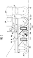
- the device 1 forming a screw for emptying the residual product stored in a silo with a substantially flat bottom comprises, in the example considered here, three beams 10, 20 and 30 placed above the bottom of the silo and parallel to it, these beams generally having the same structure.
- Each beam 10, 20 and 30 is formed of a rectilinear metallic core 11a and of a rectilinear metallic profile 11b which extend substantially over the same length (FIG. 3).
- the profile 11b is fixed by a face against a longitudinal face of the core 11a and parallel to it, and it extends over a height of approximately 30 cm.
- the upper part of the profile 11b is folded forward at its upper part, that is to say on the side opposite the core 11a.
- the longitudinal face of the section 11b, opposite its face fixed to the core 11a will be called the front face.
- the first beam 10 (FIG. 1) is pivotally mounted by one 10a of its so-called internal ends which is articulated around a pivot 2 situated generally above the evacuation opening 3 provided for example at the center of the bottom of the silo and delimited by a bucket 4.
- the pivot 2 is fixed to a support 5 placed in the center of the bucket 4 and connected by connecting bars 5a to the edges of the bucket 4.
- the beam 10 is supported by a plate 12.
- This plate 12 ( Figures 2 and 3) supports an engine group comprising two electric motors M1 and M′1, and a drive system such as a wheel 15 by means of which the beam 10 is supported on the bottom of the silo.
- the axis of rotation of the wheel 15 is substantially parallel to the beam 10, so as to allow the pivoting movement of the latter, and it is connected to the output shaft of the motor M′1.
- the first beam 10 rotatably supports an endless screw 16 carried by bearings fixed to the front face of the profile 11b, said screw extending parallel to the beam.
- the worm 16 overhangs the discharge opening 3 so that the product which it conveys flows through this opening.
- the axis of the worm 16 is coupled to the output shaft of the motor M1 by a system 17 with sprockets and chain for example.
- the second and third beams 20 and 30 have a structure similar to that of the first beam 10.
- the beam 20 is mounted articulated by a pivot 6 supported in rotation by the plate 12 of the first beam 10, while towards its so-called internal end 30a, the beam 30 is mounted articulated by a supported pivot 6 in rotation by the plate 22 of the second beam 20.
- the three beams 10, 20 and 30 are parallel to each other, they are offset from each other.
- the second beam 20 is in front of the first beam 10 considering the direction of pivoting
- the third beam 30 is in front of the second beam 20.
- the internal end of the second worm 26 of the second beam 20 extends beyond the end of the worm 16 of the first beam 10, on the external end side of this, so that the product conveys by the second worm 26 is taken up by the first worm 16.
- the end of the worm screw 36 of the third beam 30, on the outer end side 30b thereof advantageously extends beyond the plate 32 for reasons which will be mentioned later.
- Means 50 are provided for controlling the pivoting of the second beam 20 relative to the first beam 10 when the latter is in motion.
- these means 50 are constituted by an electrical device such as a switch 51 mounted in the motor control circuit M'2 of the drive system 25 of the second beam 20.
- This switch 51 is supported by the plate 12 in the vicinity of the articulation pivot 6 of the two beams 10 and 20.
- the triggering member of this switch consists of a finger 52 mounted at the upper end of the articulation pivot 6.
- means 55 are provided for controlling the pivoting of the first beam 10 relative to the second beam 20.
- These means 55 are also constituted by an electric switch 56 mounted in the motor control circuit M′1 of the drive system 15 of the first beam 10.
- This switch 56 is supported by the plate 12 in the vicinity of the articulation pivot 6 of the two beams 10 and 20.
- the triggering member of this switch 56 is the same as that of the switch 51, namely the finger 52 carried by the articulation pivot 6. Concretely, the two electrical switches 51 and 56 are located on either side of the finger 52.
- 11 is provided these same means 50 and 55 of servo-control between the beams 20 and 30.
- the device is put into operation to carry out the residual drain.
- the three respective motors M1, M2 and M3 for driving the worms 16, 26 and 36 in rotation are started sequentially, the three beams 10, 20 and 30 being substantially in line with one another. others.
- the product carried by the endless screw 36 of the third beam 30 is taken up by the endless screw 26 of the second beam 20, then taken up by the endless screw 16 of the first beam 10 to be poured into the opening of evacuation 3 from the silo.
- the drive motors M′1, M′2 and M′3 of the beams are also started, but as long as the resistance offered by the product opposes the pivoting movement of the beams 10, 20 and 30 these remain fixed. Concretely, the drive motor M′1 of the wheel 15 of the first beam 10 only comes into operation when the beam is released from the product, an instant which is detected by a photoelectric cell for example. Once the motor M′1 is controlled, the motors M′2 and M′3 for driving the beams 20 and 30 are successively started.
- the beams 10, 20 and 30 do not necessarily rotate simultaneously and at the same angle, because the quantity of the product, its structure, ... vary from place to place. For these different For this reason, the control devices 50 and 55 for pivoting the beams relative to one another have been provided.
- the radial finger 52 of the servo means 50 pivots in a determined direction and acts on the electric switch 51, which has the effect of stopping the motor M ′ 2 for driving the beam 20.
- the motor M′2 is again started as soon as the finger no longer acts on the switch 51.
- the radial finger 52 of the servo means 55 pivots in an opposite direction and acts on the electric switch 56, which has the effect of stopping the motor M′1 for driving the beam 10.
- the same servo means 50 and 55 provided between the second and third beams 20 and 30 act similarly.
- the three beams 10, 20 and 30 generally extend over a radius of the silo, and it is important to note that the end of the worm 36 which extends beyond the plate 32 of the third beam 30 comes in the vicinity of the internal lateral wall of the silo, which makes it possible to evacuate the product stored in this zone.
- the device according to the invention applies in the case of the residual emptying of various products, cereals in general, these products in bulk, granular or powdery flowing by gravity.
- the residual emptying can be entirely carried out with the device according to the invention, the assembly of the endless screws generally extending over a length corresponding to the radius of the silo.
- the invention is not limited to the embodiments given solely by way of example, and it includes all the technical equivalents described above.
- the principle of the invention applies to a number of beams at least equal to two, and a person skilled in the art can easily envisage, without departing from the scope of the invention, variants in terms of articulation systems.
- between the beams systems for controlling the pivoting movement of two consecutive beams using photoelectric cells for example, and beam drive systems based on tracks for example.
- the drive motors for the worms and beams can be of the pneumatic or hydraulic type.
- certain provisions such as the position of the drive motors and the extension of the worm of the last beam towards the wall of the silo are improvements which can be mounted on devices with a single beam.
Landscapes
- Engineering & Computer Science (AREA)
- Mechanical Engineering (AREA)
- Filling Or Emptying Of Bunkers, Hoppers, And Tanks (AREA)
- Screw Conveyors (AREA)
Applications Claiming Priority (2)
| Application Number | Priority Date | Filing Date | Title |
|---|---|---|---|
| FR9009950A FR2665427B1 (fr) | 1990-08-03 | 1990-08-03 | Dispositif formant vis de vidange du produit residuel stocke dans un silo. |
| FR9009950 | 1990-08-03 |
Publications (3)
| Publication Number | Publication Date |
|---|---|
| EP0469994A2 true EP0469994A2 (de) | 1992-02-05 |
| EP0469994A3 EP0469994A3 (en) | 1992-10-28 |
| EP0469994B1 EP0469994B1 (de) | 1996-05-01 |
Family
ID=9399400
Family Applications (1)
| Application Number | Title | Priority Date | Filing Date |
|---|---|---|---|
| EP91402148A Expired - Lifetime EP0469994B1 (de) | 1990-08-03 | 1991-07-31 | Schneckenanordnung zum Austrag des in einem Silo zurückgebliebenen Produktes |
Country Status (5)
| Country | Link |
|---|---|
| US (1) | US5203802A (de) |
| EP (1) | EP0469994B1 (de) |
| DE (2) | DE469994T1 (de) |
| ES (1) | ES2031432T1 (de) |
| FR (1) | FR2665427B1 (de) |
Families Citing this family (15)
| Publication number | Priority date | Publication date | Assignee | Title |
|---|---|---|---|---|
| US5520012A (en) * | 1995-04-14 | 1996-05-28 | Frigoscandia Equipment Ab | Crust freezer |
| US8967937B2 (en) | 2011-09-09 | 2015-03-03 | Sioux Steel Company | Modular storage bin sweep system |
| US10676294B2 (en) | 2011-09-09 | 2020-06-09 | Sioux Steel Company | Modular storage bin sweep system |
| US9643800B2 (en) * | 2013-02-23 | 2017-05-09 | Phillip Douglas | Horizontal support system |
| US9864344B2 (en) | 2013-10-16 | 2018-01-09 | Sioux Steel Company | System and method for multiple sweep proximity sensing and control |
| US10011442B2 (en) | 2014-02-10 | 2018-07-03 | Sioux Steel Company | Bin sweep support |
| US9809402B2 (en) | 2014-10-06 | 2017-11-07 | Sioux Steel Company | Segmented bin sweep system |
| US10442641B2 (en) | 2014-12-02 | 2019-10-15 | Sioux Steel Company | Bin sweep system |
| WO2016141083A1 (en) | 2015-03-02 | 2016-09-09 | Sioux Steel Company | Bin sweep power transmission system |
| US10703588B1 (en) | 2017-04-25 | 2020-07-07 | Sioux Steel Company | Bin sweep system with particle agglomeration breakup capability |
| US11299358B1 (en) | 2019-03-08 | 2022-04-12 | Sioux Steel Company | Storage bin sweep system with enhanced peripheral sweep capability |
| US11454444B1 (en) | 2019-03-08 | 2022-09-27 | Sioux Steel Company | Storage bin ventilation system and apparatus |
| US11267664B1 (en) | 2019-03-08 | 2022-03-08 | Sioux Steel Company | Bin sweep system with drive apparatus having enhanced slippage capability |
| US11618639B1 (en) | 2019-03-08 | 2023-04-04 | Sioux Steel Company | Storage bin sweep system with enhanced peripheral sweep capability |
| US11104528B1 (en) | 2019-03-08 | 2021-08-31 | Sioux Steel Company | Bin sweep system with contoured paddles |
Family Cites Families (10)
| Publication number | Priority date | Publication date | Assignee | Title |
|---|---|---|---|---|
| US2763362A (en) * | 1953-04-20 | 1956-09-18 | Greaves Joseph | Flexible grain auger |
| US2790563A (en) * | 1954-10-08 | 1957-04-30 | Edwin L Mccarthy | Apparatus for cleaning flat bottom grain tanks with side draw-off |
| US3289862A (en) * | 1965-02-10 | 1966-12-06 | Richard L Weaver | Silo unloader |
| US3301412A (en) * | 1965-03-11 | 1967-01-31 | Vandale Corp | Closure structure for silo unloader collector arm |
| US3456818A (en) * | 1967-11-29 | 1969-07-22 | Speed King Mfg Co Inc | Grain auger apparatus |
| US3647094A (en) * | 1970-10-01 | 1972-03-07 | William J Jackson | Unloader for storage bins |
| GB1570690A (en) * | 1977-11-02 | 1980-07-09 | White H | Removal of flowable material from storage bins |
| US4313705A (en) * | 1979-01-26 | 1982-02-02 | Jackson William J | Unloader for storage bins |
| DE8634115U1 (de) * | 1986-12-19 | 1987-03-19 | Saxlund, Oddmund, Arendal | Austraganordnung für Schüttgutsilo od.dgl. |
| US4861216A (en) * | 1987-01-15 | 1989-08-29 | Vth Ag | Feeding device for feeding pulverous or granular material from a container to a material consuming apparatus |
-
1990
- 1990-08-03 FR FR9009950A patent/FR2665427B1/fr not_active Expired - Lifetime
-
1991
- 1991-07-31 EP EP91402148A patent/EP0469994B1/de not_active Expired - Lifetime
- 1991-07-31 DE DE199191402148T patent/DE469994T1/de active Pending
- 1991-07-31 ES ES199191402148T patent/ES2031432T1/es active Pending
- 1991-07-31 DE DE69119157T patent/DE69119157T2/de not_active Expired - Fee Related
- 1991-08-01 US US07/739,174 patent/US5203802A/en not_active Expired - Lifetime
Also Published As
| Publication number | Publication date |
|---|---|
| DE469994T1 (de) | 1992-08-13 |
| FR2665427A1 (fr) | 1992-02-07 |
| US5203802A (en) | 1993-04-20 |
| DE69119157T2 (de) | 1996-12-05 |
| FR2665427B1 (fr) | 1992-11-27 |
| EP0469994A3 (en) | 1992-10-28 |
| EP0469994B1 (de) | 1996-05-01 |
| DE69119157D1 (de) | 1996-06-05 |
| ES2031432T1 (es) | 1992-12-16 |
Similar Documents
| Publication | Publication Date | Title |
|---|---|---|
| EP0469994B1 (de) | Schneckenanordnung zum Austrag des in einem Silo zurückgebliebenen Produktes | |
| EP1491122B1 (de) | Elektrisches Haushaltsgerät | |
| BE1005026A3 (fr) | Moissonneuse-batteuse automotrice. | |
| EP0134918B1 (de) | Betätigungsmechanismus für eine Dosierklappe | |
| FR2678585A1 (fr) | Bac gerbable emboitable a elements supports pivotants. | |
| FR2459779A1 (fr) | Mecanisme de prehension et de levage pour conteneur | |
| FR2601345A1 (fr) | Appareil d'alimentation en plaques | |
| EP0042796A1 (de) | Vorrichtung zum Entladen von Schüttgütern | |
| FR2695922A3 (fr) | Unité de trimodulaire pour convoyeurs. | |
| EP1638386B1 (de) | Aufbewahrungsvorrichtung für gemüse, insbesondere lauch, und verfahren hierfür | |
| FR2459199A1 (fr) | Appareil de maniement de marchandises palettisees, empilees en couches | |
| FR2540702A1 (fr) | Vehicule de transport de recoltes | |
| FR2852940A1 (fr) | Dispositif de transfert de charges isolees et installation de transfert correspondante | |
| CA1113432A (fr) | Dispositif de collecte de toutes matieres temporairement stockees en container a poste fixe | |
| FR2489866A1 (fr) | Appareil perfectionne pour prelever et diriger au moyen d'un bras a godets racleurs des materiaux disposes en tas des deux cotes du bras | |
| FR2584648A1 (fr) | Dispositif de guidage notamment pour engin du type robot | |
| EP1582325B1 (de) | Förderer geeignet für einen Transportbetonmischer und Betonmischer mit solchen Förderer | |
| EP1175827A1 (de) | Selbstbewegende Vorrichtung zum Entmisten mittels Abstreifen | |
| FR2868054A1 (fr) | Dispositif pour faire pivoter un convoyeur, convoyeur equipe d'un tel dispositif, et vehicule du type betonniere equipe d'un tel convoyeur | |
| FR2727096A1 (fr) | Tremie d'alimentation a bande | |
| WO1997018943A1 (fr) | Egouttoir-pressoir a chambres multiples et axes de pressage decales angulairement | |
| FR3088922A1 (fr) | Dispositif de vidange de silo notamment pour atmosphère explosive | |
| FR2789375A1 (fr) | Station pour distribuer des produits d'une ligne de convoyage vers une ligne d'evacuation | |
| FR2828179A1 (fr) | Procede et dispositif de vidange de silo | |
| EP0187565A1 (de) | Füllrohr für Gewichtsdosiermaschine |
Legal Events
| Date | Code | Title | Description |
|---|---|---|---|
| PUAI | Public reference made under article 153(3) epc to a published international application that has entered the european phase |
Free format text: ORIGINAL CODE: 0009012 |
|
| AK | Designated contracting states |
Kind code of ref document: A2 Designated state(s): BE DE ES GB IT LU NL |
|
| ITCL | It: translation for ep claims filed |
Representative=s name: NOTARBARTOLO & GERVASI S.R.L. |
|
| TCNL | Nl: translation of patent claims filed | ||
| DET | De: translation of patent claims | ||
| PUAL | Search report despatched |
Free format text: ORIGINAL CODE: 0009013 |
|
| AK | Designated contracting states |
Kind code of ref document: A3 Designated state(s): BE DE ES GB IT LU NL |
|
| REG | Reference to a national code |
Ref country code: ES Ref legal event code: BA2A Ref document number: 2031432 Country of ref document: ES Kind code of ref document: T1 |
|
| 17P | Request for examination filed |
Effective date: 19930422 |
|
| 17Q | First examination report despatched |
Effective date: 19941229 |
|
| GRAH | Despatch of communication of intention to grant a patent |
Free format text: ORIGINAL CODE: EPIDOS IGRA |
|
| GRAA | (expected) grant |
Free format text: ORIGINAL CODE: 0009210 |
|
| AK | Designated contracting states |
Kind code of ref document: B1 Designated state(s): BE DE ES GB IT LU NL |
|
| PG25 | Lapsed in a contracting state [announced via postgrant information from national office to epo] |
Ref country code: IT Free format text: LAPSE BECAUSE OF FAILURE TO SUBMIT A TRANSLATION OF THE DESCRIPTION OR TO PAY THE FEE WITHIN THE PRE;WARNING: LAPSES OF ITALIAN PATENTS WITH EFFECTIVE DATE BEFORE 2007 MAY HAVE OCCURRED AT ANY TIME BEFORE 2007. THE CORRECT EFFECTIVE DATE MAY BE DIFFERENT FROM THE ONE RECORDED.SCRIBED TIME-LIMIT Effective date: 19960501 Ref country code: GB Effective date: 19960501 Ref country code: NL Free format text: LAPSE BECAUSE OF FAILURE TO SUBMIT A TRANSLATION OF THE DESCRIPTION OR TO PAY THE FEE WITHIN THE PRESCRIBED TIME-LIMIT Effective date: 19960501 |
|
| REF | Corresponds to: |
Ref document number: 69119157 Country of ref document: DE Date of ref document: 19960605 |
|
| PG25 | Lapsed in a contracting state [announced via postgrant information from national office to epo] |
Ref country code: LU Free format text: LAPSE BECAUSE OF NON-PAYMENT OF DUE FEES Effective date: 19960731 |
|
| PG25 | Lapsed in a contracting state [announced via postgrant information from national office to epo] |
Ref country code: ES Free format text: LAPSE BECAUSE OF FAILURE TO SUBMIT A TRANSLATION OF THE DESCRIPTION OR TO PAY THE FEE WITHIN THE PRESCRIBED TIME-LIMIT Effective date: 19960812 |
|
| NLV1 | Nl: lapsed or annulled due to failure to fulfill the requirements of art. 29p and 29m of the patents act | ||
| GBV | Gb: ep patent (uk) treated as always having been void in accordance with gb section 77(7)/1977 [no translation filed] |
Effective date: 19960501 |
|
| PLBE | No opposition filed within time limit |
Free format text: ORIGINAL CODE: 0009261 |
|
| STAA | Information on the status of an ep patent application or granted ep patent |
Free format text: STATUS: NO OPPOSITION FILED WITHIN TIME LIMIT |
|
| 26N | No opposition filed | ||
| PGFP | Annual fee paid to national office [announced via postgrant information from national office to epo] |
Ref country code: DE Payment date: 20070822 Year of fee payment: 17 |
|
| PGFP | Annual fee paid to national office [announced via postgrant information from national office to epo] |
Ref country code: BE Payment date: 20070726 Year of fee payment: 17 |
|
| PG25 | Lapsed in a contracting state [announced via postgrant information from national office to epo] |
Ref country code: DE Free format text: LAPSE BECAUSE OF NON-PAYMENT OF DUE FEES Effective date: 20090203 |
|
| PG25 | Lapsed in a contracting state [announced via postgrant information from national office to epo] |
Ref country code: BE Free format text: LAPSE BECAUSE OF NON-PAYMENT OF DUE FEES Effective date: 20080731 |