EP0470453A1 - Starter électronique avec circuit de répétition - Google Patents
Starter électronique avec circuit de répétition Download PDFInfo
- Publication number
- EP0470453A1 EP0470453A1 EP91112565A EP91112565A EP0470453A1 EP 0470453 A1 EP0470453 A1 EP 0470453A1 EP 91112565 A EP91112565 A EP 91112565A EP 91112565 A EP91112565 A EP 91112565A EP 0470453 A1 EP0470453 A1 EP 0470453A1
- Authority
- EP
- European Patent Office
- Prior art keywords
- lamp
- voltage
- circuit
- electronic ballast
- temperature
- Prior art date
- Legal status (The legal status is an assumption and is not a legal conclusion. Google has not performed a legal analysis and makes no representation as to the accuracy of the status listed.)
- Granted
Links
- 239000003990 capacitor Substances 0.000 claims description 14
- 230000001419 dependent effect Effects 0.000 claims description 7
- 239000004065 semiconductor Substances 0.000 claims description 5
- 239000000758 substrate Substances 0.000 claims description 4
- 238000013021 overheating Methods 0.000 abstract 1
- YCKRFDGAMUMZLT-UHFFFAOYSA-N Fluorine atom Chemical compound [F] YCKRFDGAMUMZLT-UHFFFAOYSA-N 0.000 description 7
- 229910052731 fluorine Inorganic materials 0.000 description 7
- 239000011737 fluorine Substances 0.000 description 7
- 230000000903 blocking effect Effects 0.000 description 1
- 230000002950 deficient Effects 0.000 description 1
- 230000003252 repetitive effect Effects 0.000 description 1
- 239000007858 starting material Substances 0.000 description 1
Images


Classifications
-
- H—ELECTRICITY
- H05—ELECTRIC TECHNIQUES NOT OTHERWISE PROVIDED FOR
- H05B—ELECTRIC HEATING; ELECTRIC LIGHT SOURCES NOT OTHERWISE PROVIDED FOR; CIRCUIT ARRANGEMENTS FOR ELECTRIC LIGHT SOURCES, IN GENERAL
- H05B41/00—Circuit arrangements or apparatus for igniting or operating discharge lamps
- H05B41/02—Details
- H05B41/04—Starting switches
- H05B41/042—Starting switches using semiconductor devices
- H05B41/044—Starting switches using semiconductor devices for lamp provided with pre-heating electrodes
- H05B41/046—Starting switches using semiconductor devices for lamp provided with pre-heating electrodes using controlled semiconductor devices
Definitions
- the invention relates to an electronic ballast according to the preamble of claim 1
- ballast is e.g. known from European Patent Application No. 118 309.
- a circuit is preferably also provided which deactivates the repetition circuit when a predetermined temperature is reached, which is determined by means of a temperature sensor. This prevents possible damage to the ballast due to the repetition of the starting process.
- the temperature sensor is arranged on a common substrate together with the semiconductor switches and / or diodes and / or high-voltage resistors carrying the preheating current.
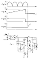
- FIG. 1 shows a lamp circuit with a fluorescent lamp connected to AC voltage (as a rule mains voltage).
- AC voltage as a rule mains voltage
- the connection is made in a known manner via an inductor L and at most with a capacitor C.
- an electronic ballast with a fluorine actuator 3 is shown, as is known in principle from European Patent Application No. 118 309. Its function can be explained on the basis of the voltage profiles according to FIGS. 2a to 2d.
- the Fluoractor 3 is controlled via its control input and goes into the conductive state.
- the preheating current L flows through the hot cathodes of the lamp 1.
- the capacitor C1 is charged; the corresponding voltage U2 is ramped with a superimposed ripple.
- FIG. 1 An embodiment of the repetition circuit according to the invention is shown in Figure 1 with the transistors T1, T2 and T3.
- the circuit responds to the voltage U4 across the lamp, which is much lower when the lamp is on than when the lamp is not on (not successfully ignited).
- the operating voltage is, for example, approx. 120 volts, whereas the voltage for a non-burning lamp is 230 volts.
- the repeater circuit responds to this difference in order to initiate a repetition when the lamp is not lit.
- the criterion used here is the voltage U5 across a capacitor C2 which is connected to the lamp voltage U4 via a resistor.
- the ramp-shaped voltage U5 (FIG. 3b) reaches the value of the Zener voltage U z of the Zener diode Z1. This leads to the switching of the transistors T1 to T3.
- capacitor C2 is discharged.
- the transistor T3 is connected to the time-determining capacitor C1 of the starter circuit. This capacitor C1 is discharged by the transistor T3, or the voltage U2 is set to a low value. This means that the thyristor 4 blocks again at the next zero point of the voltage U4.
- the transistor T3 also goes into the off state due to the discharge of C2 or the drop in U5.
- Thyristor 4 blocks and the high potential of U3 allows the fluorine actuator to conduct.
- the voltage U2 across the capacitor C1 rises in a ramp until the thyristor 4 switches through.
- the holding current is reached by the fluorine actuator 3, it blocks and a renewed ignition pulse is generated.
- the voltage U4 drops to the lower operating voltage, for example to 120 volts, which means that the voltage U5 does not reach the value U z .
- the repeater circuit remains inactive. If the lamp does not ignite again, the repetition process begins again.
- the high voltage U4 causes the voltage U5 to rise to the value U z , the transistors T1 to T3 switch through briefly, T3 discharges C1 and the Fluoractor 3 returns to the control state for preheating.
- an NTC resistor 6 is connected in parallel with the capacitor C2 as a temperature sensor.
- the resistance value of the parallel circuit NTC 6 and R9 drops to a value that prevents the capacitor C2 from charging up to the level U z ; the repetition circuit is thus deactivated as long as the temperature at the temperature sensor is higher than the predetermined value, for example 90 degrees Celsius.
- FIG. 5 shows the different course of the switching thresholds for T1, Z1 and NTC 6, thyristor 7. At temperatures of, for example, below 90 degrees Celsius, U5 first reaches the switching threshold U z of the repetition circuit, which is thus activated. At temperatures above 90 degrees Celsius, the temperature-dependent threshold voltage U s is first reached, at which the thyristor 7 switches on. The repeater circuit is not active.
- the temperature sensor 6 is preferably in heat flow connection with at least one element carrying the preheating current, for example with the fluorine actuator, the rectifier diodes, the high-voltage resistors.
- at least one element carrying the preheating current for example with the fluorine actuator, the rectifier diodes, the high-voltage resistors.
- several of these elements and the temperature sensor are arranged on a common, heat-conducting substrate, for example an A12 0 3 substrate.
Landscapes
- Circuit Arrangements For Discharge Lamps (AREA)
- Interface Circuits In Exchanges (AREA)
Applications Claiming Priority (2)
| Application Number | Priority Date | Filing Date | Title |
|---|---|---|---|
| CH2607/90 | 1990-08-10 | ||
| CH2607/90A CH680968A5 (fr) | 1990-08-10 | 1990-08-10 |
Publications (2)
| Publication Number | Publication Date |
|---|---|
| EP0470453A1 true EP0470453A1 (fr) | 1992-02-12 |
| EP0470453B1 EP0470453B1 (fr) | 1995-09-20 |
Family
ID=4237570
Family Applications (1)
| Application Number | Title | Priority Date | Filing Date |
|---|---|---|---|
| EP91112565A Expired - Lifetime EP0470453B1 (fr) | 1990-08-10 | 1991-07-26 | Starter électronique avec circuit de répétition |
Country Status (4)
| Country | Link |
|---|---|
| EP (1) | EP0470453B1 (fr) |
| AT (1) | ATE128315T1 (fr) |
| CH (1) | CH680968A5 (fr) |
| DE (1) | DE59106515D1 (fr) |
Cited By (2)
| Publication number | Priority date | Publication date | Assignee | Title |
|---|---|---|---|---|
| WO1996022007A1 (fr) * | 1995-01-13 | 1996-07-18 | Yeong Choon Chung | Demarreur electronique pour lampe fluorescente |
| WO2009101552A1 (fr) | 2008-02-14 | 2009-08-20 | Koninklijke Philips Electronics N.V. | Dispositif de commande de lampe à décharge |
Families Citing this family (1)
| Publication number | Priority date | Publication date | Assignee | Title |
|---|---|---|---|---|
| US3082193A (en) * | 1958-03-06 | 1963-03-19 | Yardney International Corp | Metal-polyvinylpyrrolidone compound and process for preparing same |
Citations (3)
| Publication number | Priority date | Publication date | Assignee | Title |
|---|---|---|---|---|
| DE2323011A1 (de) * | 1972-05-09 | 1973-11-22 | Philips Nv | Vorrichtung zur zuendung und speisung einer entladungslampe |
| EP0078790A2 (fr) * | 1981-11-02 | 1983-05-11 | Franz Wittmann | Dispositif de circuit pour l'ignition électronique de lampes à décharge de gaz |
| GB2201307A (en) * | 1987-02-12 | 1988-08-24 | David John Martin | Electronic starter for discharge lamps |
-
1990
- 1990-08-10 CH CH2607/90A patent/CH680968A5/de not_active IP Right Cessation
-
1991
- 1991-07-26 DE DE59106515T patent/DE59106515D1/de not_active Expired - Fee Related
- 1991-07-26 EP EP91112565A patent/EP0470453B1/fr not_active Expired - Lifetime
- 1991-07-26 AT AT91112565T patent/ATE128315T1/de not_active IP Right Cessation
Patent Citations (3)
| Publication number | Priority date | Publication date | Assignee | Title |
|---|---|---|---|---|
| DE2323011A1 (de) * | 1972-05-09 | 1973-11-22 | Philips Nv | Vorrichtung zur zuendung und speisung einer entladungslampe |
| EP0078790A2 (fr) * | 1981-11-02 | 1983-05-11 | Franz Wittmann | Dispositif de circuit pour l'ignition électronique de lampes à décharge de gaz |
| GB2201307A (en) * | 1987-02-12 | 1988-08-24 | David John Martin | Electronic starter for discharge lamps |
Cited By (2)
| Publication number | Priority date | Publication date | Assignee | Title |
|---|---|---|---|---|
| WO1996022007A1 (fr) * | 1995-01-13 | 1996-07-18 | Yeong Choon Chung | Demarreur electronique pour lampe fluorescente |
| WO2009101552A1 (fr) | 2008-02-14 | 2009-08-20 | Koninklijke Philips Electronics N.V. | Dispositif de commande de lampe à décharge |
Also Published As
| Publication number | Publication date |
|---|---|
| CH680968A5 (fr) | 1992-12-15 |
| EP0470453B1 (fr) | 1995-09-20 |
| DE59106515D1 (de) | 1995-10-26 |
| ATE128315T1 (de) | 1995-10-15 |
Similar Documents
| Publication | Publication Date | Title |
|---|---|---|
| DE69628739T2 (de) | Steuerung und überwachung von dimmbaren vorschaltgeräten mit breitem beleuchtungshub | |
| DE2323011C3 (de) | Schaltungsanordnung zur Zündung und zum Betrieb einer Gasentladungslampe | |
| EP1519638B1 (fr) | Méthode pour commander une lampe à décharge basse pression | |
| EP0800335B1 (fr) | Circuit pour alimenter des lampes électriques | |
| CH663508A5 (de) | Elektronisches vorschaltgeraet fuer fluoreszenzlampen sowie verfahren zu dessen betrieb. | |
| EP0054301B1 (fr) | Dispositif d'allumage pour lampe à décharge à basse pression | |
| EP0146683A1 (fr) | Onduleur | |
| DE69322676T2 (de) | Hochdruck-Dampf-Entladungslampe mit eingebauter Zündvorrichtung | |
| EP0470453A1 (fr) | Starter électronique avec circuit de répétition | |
| EP0732869A2 (fr) | Procédé et circuit pour alimenter une lampe à décharge | |
| DE2604438A1 (de) | Brenner-regelanordnung | |
| DE4216716C1 (de) | Schaltungsanordnung zum Starten einer vorheizbaren Entladungslampe | |
| DE3852745T2 (de) | Elektrische Anordnung zum Zünden und Speisen einer Gasentladungslampe. | |
| EP0104397B1 (fr) | Circuit pour diminuer la puissance consommèe par une lampe à décharge | |
| DE2502115A1 (de) | Gasentladungslampen-leuchte | |
| DE3315432A1 (de) | Zuendvorrichtung fuer eine entladungslampe | |
| DE2924069A1 (de) | Schaltungsanordnung zum zuenden und betrieb einer gas- und/oder dampfentladungslampe | |
| EP0069967A1 (fr) | Dispositif pour allumer des lampes fluorescentes | |
| DE3236852C2 (de) | Startvorrichtung für Gasentladungslampen mit heizbaren Elektroden | |
| DE2849064C2 (de) | Zündschaltung für eine Gasentladungslampe | |
| DE3613876A1 (de) | Elektronische start- und schutzvorrichtung zum vorheizen und zuenden von mit netzwechselspannung betriebenen leuchtstofflampen | |
| EP0552687B1 (fr) | Starter électronique pour tube fluorescent | |
| DE4325050C2 (de) | Schaltungsanordnung zum Starten einer vorheizbaren Entladungslampe | |
| DE2755691A1 (de) | Anordnung zum starten von leuchtstofflampen, wobei zum vorheizen der beiden heizwendel ein transformator dient | |
| DE2031516A1 (de) | Steuereinrichtung fur einen Ofen |
Legal Events
| Date | Code | Title | Description |
|---|---|---|---|
| PUAI | Public reference made under article 153(3) epc to a published international application that has entered the european phase |
Free format text: ORIGINAL CODE: 0009012 |
|
| AK | Designated contracting states |
Kind code of ref document: A1 Designated state(s): AT CH DE FR GB LI NL SE |
|
| RAP1 | Party data changed (applicant data changed or rights of an application transferred) |
Owner name: KNOBEL AG LICHTTECHNISCHE KOMPONENTEN |
|
| 17P | Request for examination filed |
Effective date: 19920731 |
|
| 17Q | First examination report despatched |
Effective date: 19940103 |
|
| GRAA | (expected) grant |
Free format text: ORIGINAL CODE: 0009210 |
|
| AK | Designated contracting states |
Kind code of ref document: B1 Designated state(s): AT CH DE FR GB LI NL SE |
|
| PG25 | Lapsed in a contracting state [announced via postgrant information from national office to epo] |
Ref country code: NL Free format text: LAPSE BECAUSE OF FAILURE TO SUBMIT A TRANSLATION OF THE DESCRIPTION OR TO PAY THE FEE WITHIN THE PRESCRIBED TIME-LIMIT Effective date: 19950920 Ref country code: GB Effective date: 19950920 |
|
| REF | Corresponds to: |
Ref document number: 128315 Country of ref document: AT Date of ref document: 19951015 Kind code of ref document: T |
|
| REF | Corresponds to: |
Ref document number: 59106515 Country of ref document: DE Date of ref document: 19951026 |
|
| PG25 | Lapsed in a contracting state [announced via postgrant information from national office to epo] |
Ref country code: SE Effective date: 19951220 |
|
| ET | Fr: translation filed | ||
| NLV1 | Nl: lapsed or annulled due to failure to fulfill the requirements of art. 29p and 29m of the patents act | ||
| GBV | Gb: ep patent (uk) treated as always having been void in accordance with gb section 77(7)/1977 [no translation filed] |
Effective date: 19950920 |
|
| PLBE | No opposition filed within time limit |
Free format text: ORIGINAL CODE: 0009261 |
|
| STAA | Information on the status of an ep patent application or granted ep patent |
Free format text: STATUS: NO OPPOSITION FILED WITHIN TIME LIMIT |
|
| 26N | No opposition filed | ||
| PGFP | Annual fee paid to national office [announced via postgrant information from national office to epo] |
Ref country code: FR Payment date: 19980616 Year of fee payment: 8 |
|
| PGFP | Annual fee paid to national office [announced via postgrant information from national office to epo] |
Ref country code: DE Payment date: 19980707 Year of fee payment: 8 |
|
| PGFP | Annual fee paid to national office [announced via postgrant information from national office to epo] |
Ref country code: AT Payment date: 19980727 Year of fee payment: 8 |
|
| PGFP | Annual fee paid to national office [announced via postgrant information from national office to epo] |
Ref country code: CH Payment date: 19980929 Year of fee payment: 8 |
|
| PG25 | Lapsed in a contracting state [announced via postgrant information from national office to epo] |
Ref country code: AT Free format text: LAPSE BECAUSE OF NON-PAYMENT OF DUE FEES Effective date: 19990726 |
|
| PG25 | Lapsed in a contracting state [announced via postgrant information from national office to epo] |
Ref country code: LI Free format text: LAPSE BECAUSE OF NON-PAYMENT OF DUE FEES Effective date: 19990731 Ref country code: FR Free format text: THE PATENT HAS BEEN ANNULLED BY A DECISION OF A NATIONAL AUTHORITY Effective date: 19990731 Ref country code: CH Free format text: LAPSE BECAUSE OF NON-PAYMENT OF DUE FEES Effective date: 19990731 |
|
| REG | Reference to a national code |
Ref country code: CH Ref legal event code: PL |
|
| PG25 | Lapsed in a contracting state [announced via postgrant information from national office to epo] |
Ref country code: DE Free format text: LAPSE BECAUSE OF NON-PAYMENT OF DUE FEES Effective date: 20000503 |
|
| REG | Reference to a national code |
Ref country code: FR Ref legal event code: ST |