EP0470460A1 - Verfahren zur Herstellung von Azomethinen - Google Patents
Verfahren zur Herstellung von Azomethinen Download PDFInfo
- Publication number
- EP0470460A1 EP0470460A1 EP91112633A EP91112633A EP0470460A1 EP 0470460 A1 EP0470460 A1 EP 0470460A1 EP 91112633 A EP91112633 A EP 91112633A EP 91112633 A EP91112633 A EP 91112633A EP 0470460 A1 EP0470460 A1 EP 0470460A1
- Authority
- EP
- European Patent Office
- Prior art keywords
- formula
- reactor
- particularly preferably
- independently
- column
- Prior art date
- Legal status (The legal status is an assumption and is not a legal conclusion. Google has not performed a legal analysis and makes no representation as to the accuracy of the status listed.)
- Granted
Links
Classifications
-
- C—CHEMISTRY; METALLURGY
- C07—ORGANIC CHEMISTRY
- C07C—ACYCLIC OR CARBOCYCLIC COMPOUNDS
- C07C251/00—Compounds containing nitrogen atoms doubly-bound to a carbon skeleton
- C07C251/02—Compounds containing nitrogen atoms doubly-bound to a carbon skeleton containing imino groups
- C07C251/20—Compounds containing nitrogen atoms doubly-bound to a carbon skeleton containing imino groups having carbon atoms of imino groups being part of rings other than six-membered aromatic rings
-
- C—CHEMISTRY; METALLURGY
- C07—ORGANIC CHEMISTRY
- C07C—ACYCLIC OR CARBOCYCLIC COMPOUNDS
- C07C249/00—Preparation of compounds containing nitrogen atoms doubly-bound to a carbon skeleton
- C07C249/02—Preparation of compounds containing nitrogen atoms doubly-bound to a carbon skeleton of compounds containing imino groups
Definitions
- the present invention relates to a process for the condensation of optionally substituted cycloalkanones with optionally substituted anilines to form azomethines in a continuous reaction in a column-like reactor with an applied temperature profile.
- Azeotropic dewatering is therefore the technically most interesting process if it is possible to achieve acceptable reaction times with little excess on one of the two components without having to use large amounts of azeotropic entrainer.
- DE-AS 1 078 119 describes the condensation of N-phenyl-p-phenylene diamine with cyclohexanone without addition of catalyst; here excess cyclohexanone of 200 to 300% must be used.
- DE-OS 2 901 863 describes freshly synthesized, anhydrous, unburned calcium hydrogen phosphate, apatite of the formula Cas (PO 4 ) aOH, dried, not annealed aluminum oxide hydroxides and proton-exchanged, neutral-washed aluminum silicates of the montmorillonite type as effective catalysts for the conversion of aromatic Amines with ketones described.
- the examples in this patent application are limited to the condensation of the reactive p-phenylenediamine with methyl isobutyl ketone, using a ketone excess of 150%.
- Cycloalkanones in which R 4 is hydrogen are also preferably used.
- anilines are used in which R 8 is hydrogen.
- cycloalkanones are used in which R 3 and R 4 are hydrogen.
- alkyl groups in the substituents mentioned (alkyl, alkoxy, alkylamino, dialkylamino) straight-chain or branched C i -C 6 -alkyl groups are mentioned, such as methyl, ethyl, propyl, isopropyl, butyl, isobutyl, tert-butyl, the isomeric pentyls and Hexyle.
- the C 1 -C 4 -alkyl groups mentioned may be mentioned in a preferred manner, particularly preferably methyl and ethyl, very particularly preferably methyl.
- Aryl in the substituents mentioned are phenyl or a 5- or 6-membered heteroaryl bonded in the 2-, 3- or 4-position with 1 or 2 heteroatoms from the group NOS called.
- heteroaryl examples include: furanyl, pyrrolyl, thienyl, pyrazolyl, imidazolyl, oxazolyl, thiazolyl, pyridyl and others.
- Phenyl is preferably aryl.
- C 3 -C 6 cycloalkyl for example cyclopropyl, cyclobutyl, cyclopentyl and cyclohexyl, preferably cyclopropyl, cyclopentyl and cyclohexyl, may be mentioned.
- the cycloalkyl substituents can in turn be substituted once or twice by methyl or ethyl,
- Halogen is, for example, fluorine, chlorine, bromine, iodine, preferably fluorine, chlorine, bromine, particularly preferably fluorine and chlorine.
- X in the cycloalkyl ring in the formulas (I), (IV) and (V) can denote the methylene group -CH 2 - or a bond which is continuous between the adjacent C atoms.
- the cyclohexane skeleton is expressed, in the second case the cyclopentane skeleton.
- X preferably denotes the methylene group and thus represents the cyclohexane skeleton.
- cycloalkanones are exemplified as starting compounds: cyclopentanone, 2-methyl-cyclopentanone, 2-ethyl-cyclopentanone, 2-phenyl-cyclopentanone, cyclohexanone, 2-methyl-cyclohexanone, 4-methyl-cyclohexanone, 2-ethyl-cyclohexanone, 4-ethyl-cyclohexanone, 4-phenyl-cyclohexanone, 2-phenyl-cyclohexanone, 4-cyclohexyl-cyclohexanone, 2-cyclohexyl-cyclohexanone.
- anilines as starting compounds are given as examples: aniline, 2-methylaniline, 3-methylaniline, 4-methylaniline, 2,4-dimethylaniline, 2-ethylaniline, 4-ethylaniline, 3-methoxyaniline, 3-ethoxyaniline, 4- Aminoaniline, 4-methylamino-aniline, 4-dimethylamino-aniline, 4-phenylaniline, 2-phenylaniline, 4-phenoxyaniline, 2-phenoxyaniline, 4-phenylamino-aniline, 2-phenylamino-aniline, 2-fluoroaniline, 4-fluoroaniline, 2-chloroaniline, 4-chloroaniline.
- the molar ratio in which the cycloalkanone and the aniline are metered in is from 2: 1 to 1: 2, preferably from 1.5: 1 to 1: 1.5, particularly preferably from 1.2: 1 to 1: 1, 2, very particularly preferably from 1.1: 1 to 1: 1.1.
- azeotroping agents from the group of the aliphatic and aromatic hydrocarbons, the aliphatic and aromatic ethers and the aliphatic alcohols can be used. In these compounds, hydrogen atoms can be replaced by halogen atoms.
- azeotroping agents their mode of action and their use are generally known to the person skilled in the art. The following are examples of azeotroping agents: benzene, toluene, xylene, anisole, chlorobenzene, butanol, hexanol, methyl butyl ether, diphenyl ether, p-chloroanisole.
- the weight ratio in which an azeotrope and the sum of the starting materials are metered in is 0.001-1: 1, preferably 0.001-0.5: 1, particularly preferably 0.001-0.2: 1, very particularly preferably 0.001-0.1: 1.
- the azeotrope distilled off can be condensed outside the column-like reactor and separated into water of reaction and azeotrope. The azeotroping agent which is thus retained can be returned to the reaction of the process according to the invention.
- One of the starting materials preferably cycloalkanone, can also serve as an azeotrope, so that an azeotrope which is foreign to the system can be dispensed with.
- Acidic heterogeneous catalysts are acidic inorganic or organic solids.
- Acidic organic solids are, for example, acidic ion exchangers, preferably with a macroporous structure, as are known from DE-AS 1 113 570, DE-OS 1 595 700 and DE-OS 2 525 295. These are sulfonated polystyrene resins and polyacrylic acid resins. Perfluorinated organic sulfonated resins can also be used. Acidic phenol-formaldehyde or phenol-melamine resins can also be used.
- Oxides of metals with medium and high oxidation levels and their mixed oxides may be mentioned as inorganic, acidic solids.
- the oxides of some non-metals or semi-metals are also suitable. Examples of such metals, non-metals and semimetals are: boron 3 ', aluminum 3+ , rare earths 3+ , silicon 4+ , germanium 4+ , tin 4+ , titanium 4+ , zirconium 4+ , hafnium 4+ , vanadium 3+ , vanadium 5+ 5+ niobium, tantalum 5+, Chrom3 +, chromium 6 + 6 + molybdenum, tungsten 6 +, zinc 2+.
- acid oxides and mixed oxides containing aluminum oxide particularly preferably acidic aluminum silicates, for example those with a layer structure (so-called clays) and acidic aluminosilicates with defined microporosity (zeolites).
- acidic aluminum silicates for example those with a layer structure (so-called clays) and acidic aluminosilicates with defined microporosity (zeolites).
- the shape of such organic or inorganic solids which can be used as acidic heterogeneous catalysts can in principle be of any type. In order to maximize the load-bearing capacity of the column-like reactor, however, it is above all necessary to ensure a gas flow which is less hindered (pressure loss in the column is as low as possible). This is achieved, inter alia, by choosing the shape and size of the particles in accordance with the shape and size of common packing elements for distillation columns.
- the inorganic or organic solids are shaped with suitable binders, as are known to the person skilled in the art, to give correspondingly lumpy fillers, to extrudates, to Raschig rings, Pall rings, saddle bodies and others.
- the organic or inorganic solids can also be applied and bound as a fine powder on inert ceramic bodies of a suitable shape.
- the techniques for producing such molded parts are known in principle to the person skilled in the art.
- the organic and inorganic solids mentioned the inorganic solids are preferred because of the higher thermal stability.
- the exposure of the organic or inorganic solids mentioned as acidic heterogeneous catalysts, expressed in g / gh, is 0.1-10, preferably 0.2-6, particularly preferably 0.3-5 and very particularly preferably 0.4- 3rd
- the process according to the invention is distinguished by the fact that the condensation is carried out in a column-like reactor suitable for continuous reaction control, on the longitudinal axis of which a temperature profile is applied.
- the column-like reactor with the exception of addition and removal areas for the reactants and products, is at least partially filled with an acidic heterogeneous catalyst in particulate form, as described above, for example in the sense of a distillation column.
- the sections not filled with catalyst contain inert packing, as are known to those skilled in the art for distillation purposes, in a shape of about the type mentioned above or those not with a catalyst filled sections of the reactor contain column trays, for example in the form of bubble trays.
- the sections of the column-like reactor which are filled with catalyst or with inert packing are delimited by sieve trays of a suitable mesh size in order to prevent the catalyst or packing from being flushed out.
- the packing sections of the reactor can also contain bubble cap trays which are provided with screens in the manner described.
- the column-like reactor can be widened or narrowed in various sections of its total length, in particular in the sections filled with catalyst. Because of the simpler handling when charging the reactor with catalyst or packing elements, however, a tube without such changes in radius or at most with an expansion is preferably used as the reactor.
- the catalyst is located in any section of the column-like reactor, taking into account the temperature profile described below. As such an arbitrary section for the loading with catalyst, a region between the upper and the lower eighth, preferably between the upper and the lower quarter, particularly preferably between the upper and the lower third of the total length of the column-like reactor may be mentioned.
- a temperature profile is applied to the column-like reactor.
- This temperature profile encompasses the temperature range from 10-300 C, preferably 15-250 C, particularly preferably 20-200 C.
- these sections are provided with insulation or with a thermostat, as is the case State of the chemical apparatus construction is. Thermostatization can represent heating or cooling as required.
- the sections of the column-like reactor which are filled with acidic heterogeneous catalyst should have a temperature of at most 250 ° C., preferably at most 200 ° C., particularly preferably at most 150 ° C.
- the temperature range for such sections filled with catalyst is accordingly preferably 25-160 ° C., particularly preferably 30-150 ° C., very particularly preferably 40-140 C.
- the temperature setting mentioned for the sections of the reactor charged with catalyst can be achieved in the aforementioned manner by insulation or complete or partial thermostatting, preferably by insulation.
- the section of the reactor above the catalyst charge has a lower temperature than that of the catalyst charge, for example 15-100 ° C., preferably 10-80 ° C., particularly preferably 5-70 ° C. less than the catalyst charge.
- the section of the reactor below the catalyst charge has a higher temperature than that of the catalyst charge, for example 20-100 C, preferably 25-90 C, particularly preferably 25-80 ° C more than the catalyst charge.
- the lower temperature above the catalyst charge can decrease continuously or in several stages towards the upper end of the reactor.
- the temperature of the reactor below the catalyst charge can correspondingly drop to the lower Increase the reactor end continuously or in several sections. Depending on the desired setting of this decreasing or increasing temperature, this can be done by mere insulation or by appropriate thermostatting (cooling or heating).
- a temperature gradient can also be created along the catalyst charge, with lower temperatures upwards and higher temperatures downwards.
- the column-like reactor is heated at its lower end by means of a heating coil, a heating jacket or an external heater.
- the equipment of the column-like reactor also includes a bottom circulation of the azomethine to be removed as a process product.
- the temperature of the heating medium for heating the lower column section with the bottom circulation should not be higher than 100 ° C., preferably not higher than 80 ° C., particularly preferably not higher than 60 ° C., very particularly preferably not higher than 40 ° C. above the boiling point of the product Azomethine to be removed are under the respective pressure prevailing in the column.
- An additional thermostat which allows a temperature to be set between the catalyst filling and the end of the reactor, is preferably attached below the catalyst filling.
- the heating liquid for this thermostatting should have a return temperature of not higher than 60 C, preferably not higher than 40 C, particularly preferably not higher than 20 C above the boiling temperature of the column contents at this point under the operating pressure there.
- the process according to the invention is carried out in a pressure range from 0.5 mbar to 3 bar, preferably from 1 mbar to 1 bar, particularly preferably from 2 to 250 mbar, very particularly preferably from 3 to 180 mbar.
- the column-like reactor is equipped at its upper low temperature end with a vacuum pump which can be switched on upstream or downstream of the condenser for the water to be removed azeotropically.
- the input materials can be fed into the reactor individually or as a mixture above the catalyst at any point in the low temperature range. They are preferably fed in as a mixture immediately above the catalyst charge. In a particularly preferred manner, the mixture is fed into the reactor at the point at which the ratio of the starting materials in the liquid phase in the reactor is equal to the ratio of the mixture to be fed. In the event that one of the feedstocks is underrepresented due to its greater volatility in the catalyst charge, it can, however, be fed in completely or partially below the catalyst charge and in this way can be countered to the other reactant entirely or partially in countercurrent.
- a separate azeotrope it can also be fed in separately from the starting materials; however, it is preferably fed in with the mixture of the starting materials or at least mixed with one of the starting materials.
- the azomethine as reaction product is removed at the lower end of the reactor in the high temperature range, for example from the bottom circulation.
- the product is usually very pure and can be used without further purification.
- the desired azomethine can be removed from the column-like reactor at a point above the decrease in the number of such non-volatile by-products, in a manner known to the process engineer, where maximum purity is guaranteed.
- the azomethine removed in the high temperature range is also in the high temperature range, i.e. in any case, the inert gas stream fed in below the catalyst charge is counter-directed.
- inert gases are: air, nitrogen, argon or methane, all of which are preferably used in dried form.
- water of reaction is removed as an azeotrope and separated in a separating vessel into an aqueous and an organic phase of the azeotrope.
- the organic phase is preferably returned to the reactor, in particular if one of the reactants is the azeotrope at the same time; this can be done at one of the above locations.
- the advantage of the method according to the invention over the prior art is the possibility of almost equimolar use of the starting materials, which can then be completely converted in a single pass. A quantitative yield is achieved while avoiding additional work-up steps.
- the reactor to be used is characterized by great simplicity and optimal use of the energy used.
- the azomethines which can be prepared according to the invention are starting materials for the hydrogenation to cyclohexylcycloalkylamines and phenylcycloalkylamines and, in the event that the cycloalkanone is a cyclohexanone, for dehydrogenation to optionally substituted diphenylamines.
- the granulate samples were ground in a micro-dismembrator (Braun, Melsungen AG). 5 ml of the granules and a tungsten carbide ball with a diameter of 9 mm were placed in the lower part of a grinding vial. The vestole was closed with the upper part and placed in the shaking container made of PTFE. The shaking container was clamped in the holder of the dismembrator and the oscillation amplitude set to approx. 10 mm deflection. The grinding was complete after 6 to 8 minutes. The finely divided powder could then be used for the above acidity determination.
- An 80 cm long mirrored vacuum column with an inner diameter of 2.5 cm was filled to a height of 15 cm with Raschig rings made of glass, to 65 cm with 200 g zeolite H-ZSM 11 granules with the dimensions 2 x 6 mm, bound with 15% Si0 2 , filled up and the pack supplemented with 15 cm Raschig rings.
- the column was provided at the lower end with a 30 cm long thermostatic evaporator tube filled with Raschig rings with an inner diameter of 2.5 cm.
- the column head consisted of a distillation bridge with a thermometer and a dropping funnel. Both the evaporator and the bridge were each equipped with a vacuum extraction unit for discharging liquids.
- the lower unit was connected to a rotameter with a diaphragm metering valve.
- the distillation bridge was connected to a water jet pump with an electronically controlled final vacuum and the pressure was set to 60 mbar.
- a nitrogen counterflow of 14 IN 2 / min was set at 60 mbar.
- the evaporator was thermostatted to 180 ° C. After a short start-up phase, stationary conditions emerged. While 98.6 g / h of 100% anil, contaminated with traces of less than 0.1% of higher-boiling components, emerged at the evaporator outlet, a mixture of 10.2 g / h at the column head condensed at a temperature of 45 to 48 ° C. h water and 11.2 g / h cyclohexanone. The apparatus was operated for 1000 hours without deactivating the catalyst.
- Example 2 A 90 cm column with a 15 cm long thermostattable area 30 cm from the lower end was surrounded with the periphery described in Example 1.
- the apparatus was set to 45 cm, i.e. filled with Raschig rings to the end of the liquid jacket.
- 45 g of a mixture of 1.2 moles of cyclohexanone and 1 mole of aniline were metered in at a nitrogen countercurrent of 2 to 3 l / h at 60 mbar.
- the evaporator temperature was set to 200 C, the liquid jacket thermostated to 105 ° C.
- a 135 cm column (inner diameter 2.5 cm) with a 20 cm long thermostatic region 35 cm from the lower end and with a 10 cm long thermostatic region 95 cm from the lower end was provided with the periphery described in Example 1.
- 110 g of KAO (2-3 mm) was added to the 40 cm long insulated zone between the thermostattable areas, the rest of the column was filled with Raschig rings.
- 275 g of a mixture of 1.18 mol of cyclohexanone and 1 mol of aniline were metered into the upper thermostatic range per hour.
- the evaporator temperature was at 210 ° C, that of the lower thermosta tized area to 115 ° C, that of the upper thermostated area to 35 ° C. 228 g / h of anil were obtained at the evaporator outlet, while the azeotrope, consisting of 23.7 g / h of water and 23.3 g / h of cyclohexanone, condensed at 39-40 ° C. at the top of the column.
- the apparatus was operated for 800 hours without loss of activity and the experiment was ended without any signs of a beginning deactivation.
- Table 1 shows the results achieved with the KAO catalyst and results obtained with other catalysts.
Landscapes
- Chemical & Material Sciences (AREA)
- Organic Chemistry (AREA)
- Organic Low-Molecular-Weight Compounds And Preparation Thereof (AREA)
- Low-Molecular Organic Synthesis Reactions Using Catalysts (AREA)
Abstract
Description
- Die vorliegende Erfindung betrifft ein Verfahren zur Kondensation von gegebenenfalls substituierten Cycloalkanonen mit gegebenenfalls substituierten Anilinen unter Bildung von Azomethinen in kontinuierlicher Reaktion in einem kolonnenartigen Reaktor mit einem angelegten Temperaturprofil.
- Die Kondensation von Cyclohexanon und Anilin zu Cyclohexylidenanilin mit Zinkchlorid als Katalysator ist seit langem bekannt (Ber. 53 (1920), 345-354). Für schwierige Fälle in solchen Kondensationen wurde das Katalysatorsystem HCI-ZnC12 eingesetzt (Ber. 46 (1913), 2718).
- Die Kondensation von aromatischen Aminen mit Cyclohexanonen ist eine Gleichgewichtsreaktion mit geringer Wärmetönung. Sie wird zugunsten des Azomethins (Schiff'sche Base) verschoben, wenn man dem System das entstehende Reaktionswasser entzieht. Im allgemeinen erreicht man dies durch azeotrope Destillation, wozu gegegebenenfalls ein inertes Schleppmittel, wie Benzol, Toluol usw. eingesetzt wird. In jüngerer Zeit wurde zur Bindung des Reaktionswassers der Einsatz von TiC14 (J. Org. Chem. 32 (1967), 3247) oder von molaren Mengen (Butyl)2SnCl2 (Synth. Commun. 12 (1982), 495) beschrieben. Beide Verbindungen binden das entstehende Reaktionswasser unter Freisetzung von HCI.
- Andere Entwicklungen gingen dahin, daß die das Wasser bindende Spezies kovalent an das Anilin gebunden ist, beispielsweise in Form von N,N-Bis-(trimethylsilyl)-anilin (Bull. Soc. Chim. Fr. 1966, 3205), Iminophosphoranen (Angew. Chem. Int. Ed. Eng. 5 (1966), 947) sowie N-(Diphenylaluminium)-anilin (J. Org. Chem. 51 (1986), 1848).
- Eine weitere Methode, das entstehende Reaktionswasser wirkungsvoll zu binden und so bei geringen Anilin- oder Ketonüberschüssen unter milden Bedingungen arbeiten zu können, ist der Einsatz von Molekularsieben (J. Org. Chem. 36 (1971), 1570; DE-OS 2 244 238). Der Nachteil dieses zuletzt genannten Verfahrens ist die aufwendige und kostspielige Regenerierung des Molekularsiebs.
- Die azeotrope Entwässerung ist somit sicherlich das technisch interessanteste Verfahren, wenn es gelingt, mit geringen Überachüssen an einer der beiden Komponenten zu akzeptablen Reaktionszeiten zu gelangen, ohne größere Mengen an Azeotrop-Schleppmittel einsetzen zu müssen.
- In DE-AS 1 078 119 wird die Kondensation von N-Phenyl-p-phenylen-diamin mit Cyclohexanon ohne Katalysatorzusatz beschrieben; hierbei müssen Cyclohexanonüberschüsse von 200 bis 300 % eingesetzt werden.
- In DE-OS 2 525 295 wird gezeigt, daß die Reaktionszeit der Kondensation von Anilin mit 400 % Überschuß Cyclohexanon ohne Katalysator mit steigender Ansatzgröße stark zunimmt, so daß eine Übersetzung in den technischen Maßstab dicht möglich ist. Ferner wurde gezeigt, daß stark- und schwachssaure organische Harze einen günstigen Einfluß auf die Reaktionszeit besitzen.
- In DE-OS 2 901 863 werden frisch synthetisiertes, wasserfreies, nicht gebranntes Calciumhydrogenphosphat, Apatit der Formel Cas(PO4)aOH, getrocknete, nicht geglühte Aluminiumoxidhydroxide und protonengetauschte, neutral gewaschene Aluminiumsilikate vom Montmorillonit-Typ als wirkungsvolle Katalysatoren für die Umsetzung von aromatischen Aminen mit Ketonen beschrieben. Die Beispiele in dieser Patentanmeldung beschränken sich jedoch auf die Kondensation des reaktiven p-Phenylendiamins mit Methyl-isobutylketon, wobei ein Ketonüberschuß von 150 % angewandt wird.
- Es war somit wünschenswert, ein preiswertes und umweltschonendes Verfahren zur Synthese von Cycloalkylidenanilinen zu entwickeln, welches sich durch hohe Ausbeuten, eine einfache Apparatur und optimale Energieausnutzung bei minimalem Energieeinsatz auszeichnet.
- Gefunden wurde ein Verfahren, mit dem bei minimalem Überschuß an Carbonyl- oder Anilinkomponente in einem kontinuierlichen Prozeß die Azomethinverbindung mit hoher Ausbeute und in hoher Reinheit gewonnen werden kann.
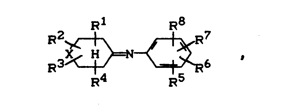
- Es wurde ein Verfahren zur Herstellung von Azomethinen der Formel

- R1, R2, R3, R4, R5, R6, R7 und R8 unabhängig voneinander Wasserstoff, geradkettiges oder verzweigtes C1-C6-Alkyl, C3-C6-Cycloalkyl oder Aryl bedeuten und
- R5, R6, R7 und R8 unabhängig voneinander zusätzlich Halogen, geradkettiges oder verzweigtes Ci-C6-alkoxy, Hydroxy, Amino, Ci-C6-Alkylamino, Di-C1-C6-alkyl-amino, Aryloxy oder Arylamino bedeuten,
- wobei Aryl für Phenyl oder für in 2-, 3- oder 4-Stellung gebundenes 5- oder 6-gliedriges Heteroaryl mit 1 oder 2 Heteroatomen aus der Gruppe N, O und S steht, und
- X -CH2- oder eine zwischen den benachbarten C-Atomen durchgehende Bindung bedeutet,
- durch Kondensation von Cycloalkanonen der Formel


- in Gegenwart von sauren heterogenen Katalysatoren unter azeotroper Entfernung des Wassers gefunden, das dadurch gekennzeichnet ist, daß die Kondensation in kontinuierlicher Reaktion in einem kolonnenartigen Reaktor mit einem angelegten Temperaturprofil durchgeführt wird, wobei die Ausgangsstoffe im Niedertemperaturbereich zugeführt werden und von den Reaktionsprodukten das azeotrop zu entfernende Reaktionswasser ebenfalls im Niedertemperturbereich und das entstehende Azomethin im Hochtemperaturbereich abgeführt werden.
- In bevorzugter Weise werden Ausgangsstoffe eingesetzt, in denen Phenyl für Aryl steht.
- In weiterhin bevorzugter Weise werden Cycloalkanone eingesetzt, in denen R4 Wasserstoff bedeutet.
- In noch weiterhin bevorzugter Weise werden Aniline eingesetzt, in denen R8 Wasserstoff bedeutet.
- In besonders bevorzugter Form werden Cycloalkanone eingesetzt, in denen R3 und R4 Wasserstoff bedeuten.
- In ebenfalls besonders bevorzugter Weise werden Aniline eingesetzt, in denen R7 und R8 Wasserstoff bedeuten.
- Des weiteren sind Cycloalkanone der Formel

- R11 und R12 unabhängig voneinander Wasserstoff, geradkettiges oder verzweigtes C1-C4-Alkyl, Cyclopropyl, Cyclopentyl, Cyclohexyl oder Phenyl bedeuten und
- X -CH2 oder eine zwischen den benachbarten C-Atomen durchgehende Bindung bedeutet.
- In besonders bevorzugter Weise werden Cycloalkanone der Formel

- R21 und R22 unabhängig voneinander Wasserstoff, Methyl oder Ethyl bedeuten und
- X die obige Bedeutung hat.
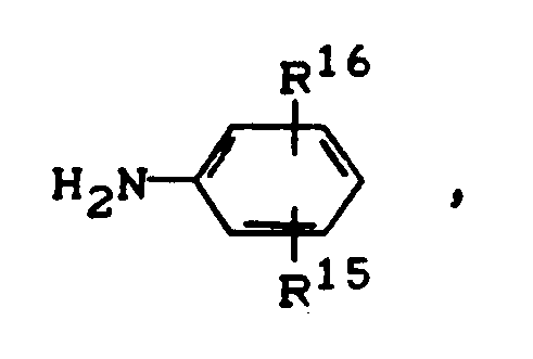
- In bevorzugter Weise werden weiterhin Aniline der Formel

- R15 und R16 unabhängig voneinander Wasserstoff, geradkettiges oder verzweigtes C1-C4-Alkyl, Phenyl, Fluor, Chlor, Brom, geradkettiges oder verzweigtes C1-C4-Alkoxy, Hydroxy, Amino, C1-C4-Alkylamino, Di-Ci-C4-alkyl-amino, Phenoxy oder Phenylamino bedeuten.
- In besonders bevorzugter Weise werden Aniline der Formel

- R25 und R26 unabhängig voneinander Wasserstoff, Methyl, Ethyl, Fluor, Chlor, Methoxy, Ethoxy, Methylamino, Ethylamino, Dimethylamino oder Diethylamino bedeuten.
- In ganz besonders bevorzugter Weise werden Aniline der Formel

- R35 und R36 unabhängig voneinander Wasserstoff, Fluor, Chlor, Methyl, Ethyl, Methoxy, Methylamino oder Dimethylamino bedeuten.
- Als Alkylgruppen in den genannten Substituenten (Alkyl, Alkoxy, Alkylamino, Dialkylamino) seien geradkettige oder verzweigte Ci-C6-Alkylgruppen genannten, wie Methyl, Ethyl, Propyl, Isopropyl, Butyl, Isobutyl, tert.-Butyl, die isomeren Pentyle und Hexyle. In bevorzugter Weise seien die genannten C1-C4-Alkylgruppen genannt, besonders bevorzugt Methyl und Ethyl, ganz besonders bevorzugt Methyl.
- Als Aryl in den genannten Substituenten (Aryl, Aryloxy, Arylamino) seien Phenyl oder ein in 2-, 3- oder 4-Stellung gebundenes 5- oder 6-gliedriges Heteroaryl mit 1 oder 2 Heteroatomen aus der Gruppe N-O-S genannt. Beispiele für solches Heteroaryl sind: Furanyl, Pyrrolyl, Thienyl, Pyrazolyl, Imidazolyl, Oxazolyl, Thiazolyl, Pyridyl und andere. In bevorzugter Weise steht Phenyl für Aryl.
- Als C3-C6-Cycloalkyl sei beispielsweise Cyclopropyl, Cyclobutyl, Cyclopentyl und Cyclohexyl, bevorzugt Cyclopropyl, Cyclopentyl und Cyclohexyl, genannt. Die Cycloalkyl-Substituenten können ihrerseits ein-oder zweimal durch Methyl oder Ethyl substituiert sein,
- Als Halogen sei beispielsweise Fluor, Chlor, Brom, lod, bevorzugt Fluor, Chlor, Brom, besonders bevorzugt Fluor und Chlor, genannt.
- Der Ausdruck "X" im Cycloalkylring in den Formeln (I), (IV) und (V) kann die Methylengruppe -CH2-oder eine zwischen den benachbarten C-Atomen durchgehende Bindung bedeuten. Im ersteren Fall wird hiermit das Cyclohexangerüst, im zweiten Fall das Cyclopentangerüst ausgedrückt. In bevorzugter Weise bedeutet X die Methylengruppe und stellt somit das Cyclohexangerüst dar.
- Folgende Cycloalkanone seien als Ausgangsverbindungen im einzelnen beispielhaft aufgeführt: Cyclopentanon, 2-Methyl-cyclopentanon, 2-Ethyl-cyclopentanon, 2-Phenyl-cyclopentanon, Cyclohexanon, 2-Methyl-cyclohexanon, 4-Methyl-cyclohexanon, 2-Ethyl-cyclohexanon, 4-Ethyl-cyclohexanon, 4-Phenyl-cyclohexanon, 2-Phenyl-cyclohexanon, 4-Cyclohexyl-cyclohexanon, 2-Cyclohexyl-cyclohexanon.
- Folgende Aniline als Ausgangsverbindungen seien im einzelnen beispielhaft aufgeführt: Anilin, 2-Methylanilin, 3-Methylanilin, 4-Methylanilin, 2,4-Dimethyl-anilin, 2-Ethylanilin, 4-Ethylanilin, 3-Methoxyanilin, 3-Ethoxyanilin, 4-Aminoanilin, 4-Methylamino-anilin, 4-Dimethylamino-anilin, 4-Phenylanilin, 2-Phenylanilin, 4-Phenoxyanilin, 2-Phenoxyanilin, 4-Phenylamino-anilin, 2-Phenylamino-anilin, 2-Fluoranilin, 4-Fluoranilin, 2-Chloranilin, 4-Chloranilin.
- Das Molverhältnis, in welchem das Cycloalkanon und das Anilin zudosiert werden, beträgt von 2:1 bis 1:2, bevorzugt von 1,5:1 bis 1:1,5, besonders bevorzugt von 1,2:1 bis 1:1,2, ganz besonders bevorzugt von 1,1:1 bis 1:1,1.
- Zur azeotropen Entfernung des Reaktionswassers können Azeotropbildner aus der Gruppe der aliphatischen und aromatischen Kohlenwasserstoffe, der aliphatischen und aromatischen Ether sowie der aliphatischen Alkohole eingesetzt werden. In diesen Verbindungen können Wasserstoffatome durch Halogenatome ersetzt sein. Diese Azeotropbildner, ihre Wirkungsweise und ihr Einsatz sind dem Fachmann grundsätzlich bekannt. Als Azeotropbildner seien beispielhaft folgende aufgeführt: Benzol, Toluol, Xylol, Anisol, Chlorbenzol, Butanol, Hexanol, Methyl-butylether, Diphenylether, p-Chloranisol. Das Gewichtsverhältnis, in dem ein Azeotropbildner und die Summe der Ausgangsstoffe zudosiert werden, beträgt 0,001-1:1, bevorzugt 0,001-0,5:1, besonders bevorzugt 0,001-0,2:1, ganz besonders bevorzugt 0,001-0,1:1. In einer dem Fachmann bekannten Weise kann das abdestillierte Azeotrop außerhalb des kolonnenartigen Reaktors kondensiert und in Reaktionswasser und Azeotropbildner geschieden werden. Der so zurückerhaltende Azeotropbildner kann erneut in die Reaktion des erfindungsgemäßen Verfahren zurückgeführt werden.
- Als Azeotropbildner kann auch einer der Ausgangsstoffe, bevorzugt das Cycloalkanon dienen, so daß auf einen systemfremden Azeotropbildner verzichtet werden kann.
- Als saure heterogene Katalysatoren kommen saure anorganische oder organische Festkörper infrage. Saure organische Festkörper sind beispielsweise saure lonenaustauscher, bevorzugt mit makroporöser Struktur, wie sie aus DE-AS 1 113 570, DE-OS 1 595 700 und DE-OS 2 525 295 bekannt sind. Es handelt sich hierbei um sulfonierte Polystyrolharze und Polyacrylsäureharze. Desweiteren sind perfluorierte organische sulfonierte Harze verwendbar. Ebenso können saure Phenol-Formaldehyd- oder Phenol-MelaminHarze eingesetzt werden.
- Als anorganische, sauer wirkende Festkörper seien Oxide von Metallen mit mittlerer und hoher Oxidationstufe und deren Mischoxide genannt. Neben Metalloxiden sind auch die Oxide einiger Nichtmetalle oder Halbmetalle geeignet. Als solche Metalle, Nichtmetalle und Halbmetalle seien beispielsweise genannt: Bor3', Aluminium3+, Seltenerden3+, Silicium4+, Germanium4+, Zinn4+, Titan4+, Zirkonium4+, Hafnium4+, Vanadium3+, Vanadium5+, Niob5+, Tantal5+, Chrom3+, Chrom6 +, Molybdän6 +, Wolfram6 +, Zink2+. Besonders bevorzugt hierunter sind saure Oxide und Mischoxide mit einem Gehalt an Aluminiumoxid, besonders bevorzugt saure Aluminiumsilikate, beispielsweise solche mit Schichtstruktur (sogenannte Clays) und saure Aluminosilikate mit definierter Mikroporosität (Zeolithe).
- Beispiele für saure anorganische oxidische Festkörper sind:
- Böhmit, γ-Al2O3, Montmorillonit, Bentonit, Glimmer, H-ZSM 11, H-ZSM 5, H-Mordenit, H-Y, SE-Y, H-Q, H-L, H-Offretit, H-ZSM12, H-ZSM23, H-Ferrierit. Anorganische Oxide und Mischoxide haben für den erfindungsgemäßen Einsatz eine BET-Oberfläche von 40-400 m2/g, bevorzugt 50-350 m2/g, besonders bevorzugt 100-300 m2/g. Speziell bei Zeolithen liegt der Bereich der BET-Oberfläche bei 20-800 m2/g, bevorzugt 30-600 m2/g, besonders bevorzugt 40-400 m2/g. Der pH-Wert einer Aufschlämmung solcher anorganischer Oxide oder Mischoxide von 1 g feingemahlenem Oxid oder Mischoxid in 40 ml 1 wäßriger NaCI-Lösung sollte zwischen 0 und 7 betragen und bevorzugt 1-6, besonders bevorzugt 2-5 sein.
- Die Form solcher als saure heterogene Katalysatoren einsetzbaren organischen oder anorganischen Festkörper kann prinzipiell beliebig sein. Um die Belastbarkeit des kolonnenartigen Reaktors zu maximieren, ist jedoch vor allem für einen wenig gehinderten Gasstrom (möglichst geringen Druckverlust in der Kolonne) zu sorgen. Dies wird unter anderem dadurch erreicht, daß man die Form und Größe der Teilchen entsprechend der Form und Größe gängiger Füllkörper für Destillationskolonnen wählt. Hierzu werden die anorganischen oder organischen Festkörper mit geeigneten Bindern, wie sie dem Fachmann bekannt sind, zu entsprechend stückigen Füllkörpern, zu Extrudaten, zu Raschigringen, Pallringen, Sattelkörpern und anderen ausgeformt. Die organischen oder anorganischen Festkörper können jedoch auch als feines Pulver auf inerten Keramikkörpern geeigneter Form aufgebracht und gebunden werden. Die Techniken zur Herstellung solcher Formteile sind dem Fachmann prinzipiell bekannt. Unter den genannten organischen und anorganischen Festkörpern sind wegen der höheren thermischen Beständigkeit die anorganischen Festkörper bevorzugt.
- Die Belastung der genannten organischen oder anorganischen Festkörper als saure heterogene Katalysatoren liegt ausgedrückt in g/g.h bei 0,1-10, bevorzugt bei 0,2-6, besonders bevorzugt bei 0,3-5 und ganz besonders bevorzugt bei 0,4-3.
- Das erfindungsgemäße Verfahren ist dadurch ausgezeichnet, daß die Kondensation in einem für kontinuierliche Reaktionsführung geeigneten kolonnenartigen Reaktor ausgeführt wird, an dessen Längsachse ein Temperaturprofil angelegt wird. Der kolonnenartige Reaktor wird mit Ausnahme von Zugabe- und Abnahmebereichen für die Reaktionspartner und -produkte mindestens teilweise mit einem sauren heterogenen Katalysator in stückiger, oben beschriebener Form, etwa im Sinne einer Destillationskolonne gefüllt. Für den Fall, daß der kolonnenartige Reaktor nicht vollständig mit dem sauren heterogenen Katalysator gefüllt ist, enthalten die nicht mit Katalysator gefüllten Abschnitte inerte Füllkörper, wie sie für Destillationszwecke dem Fachmann bekannt sind, in einer Formgebung etwa der oben genannten Art oder solche nicht mit Katalysator gefüllten Abschnitte des Reaktors enthalten Kolonnenböden, etwa in Form von Glockenböden. Selbstverständlich sind die Abschnitte des kolonnenartigen Reaktors, die mit Katalysator bzw. mit inerten Füllkörpern gefüllt sind, durch Siebböden geeigneter Maschenweite begrenzt, um ein Ausschwemmen des Katalysators bzw. der Füllkörper zu verhindern. Auch die Füllkörper-Abschnitte des Reaktors können Glockenböden enthalten, die in der beschriebenen Weise mit Sieben versehen sind.
- Grundsätzlich kann der kolonnenartige Reaktor in verschiedenen Abschnitten seiner Gesamtlänge, insbesondere in den Abschnitten mit Katalysatorfüllung, aufgeweitet oder verengt sein. Wegen der einfacheren Handhabung bei der Beschickung des Reaktors mit Katalysator bzw. Füllkörpern wird jedoch bevorzugt ein Rohr ohne solche Radiusänderungen oder allenfalls mit einer Aufweiterung als Reaktor benutzt. Der Katalysator befindet sich im Rahmen der mindestens teilweisen Befüllung in einem beliebigen Abschnitt des kolonnenartigen Reaktors unter Berücksichtigung des weiter unten beschriebenen Temperaturprofils. Als ein solcher beliebiger Abschnitt für die Beschickung mit Katalysator sei ein Bereich zwischen dem oberen und dem unteren Achtel, bevorzugt zwischen dem oberen und dem unteren Viertel, besonders bevorzugt zwischen dem oberen und dem unteren Drittel der Gesamtlänge des kolonnenartigen Reaktors genannt.
- Dem kolonnenartigen Reaktor wird erfindungsgemäß ein Temperaturprofil angelegt. Dieses Temperaturprofil umfaßt den Temperaturbereich von 10-300 C, bevorzugt 15-250 C, besonders bevorzugt 20-200 C. Zur Einstellung des Temperaturgradienten in den einzelnen Abschnitten des kolonnenartigen Reaktors werden diese Abschnitte mit einer Isolierung bzw. mit einer Thermostatisierung versehen, wie es Stand des chemischen Apparatebaus ist. Die Thermostatisierung kann hierbei je nach Bedarf eine Heizung oder eine Kühlung darstellen.
- Die Abschnitte des kolonnenartigen Reaktors, die mit saurem heterogenem Katalysator gefüllt sind, sollten eine Temperatur von höchstens 250 C, bevorzugt höchstens 200 C, besonders bevorzugt höchstens 150°C aufweisen.
- Der Temperaturbereich für solche mit Katalysator gefüllten Abschnitte beträgt demnach bevorzugt 25-160°C, besonders bevorzugt 30-150 C, ganz besonders bevorzugt 40-140 C. Die genannte Temperatureinstellung für die mit Katalysator beschickten Abschnitte des Reaktors kann in genannter Weise durch eine Isolierung oder eine vollständige oder teilweise Thermostatisierung, bevorzugt durch eine Isolierung eingehalten werden.
- Der Abschnitt des Reaktors oberhalb der Katalysatorfüllung weist eine niedrigere Temperatur als die der Katalysatorfüllung auf, beispielsweise 15-100 C, bevorzugt 10-80°C, besonders bevorzugt 5-70 °C weniger als die Katalysatorfüllung. Der Abschnitt des Reaktors unterhalb der Katalysatorfüllung weist eine höhere Temperatur als die der Katalysatorfüllung auf, beispielsweise 20-100 C, bevorzugt 25-90 C, besonders bevorzugt 25-80 °C mehr als die Katalysatorfüllung. Die niedrigere Temperatur oberhalb der Katalysatorfüllung kann hierbei zum oberen Reaktorende hin kontinuerlich oder in mehreren Stufen abnehmen. Die Temperatur des Reaktors unterhalb der Katalysatorfüllung kann in entsprechender Weise zum unteren Reaktorende hin kontinuierlich oder in mehreren Abschnitten zunehmen. Je nach gewünschter Einstellung dieser abnehmenden bzw. zunehmenden Temperatur kann dies durch bloße Isolierung oder durch entsprechende Thermostatisierung (Kühlung bzw. Heizung) erfolgen. Auch längs der Katalysatorfüllung kann ein Temperaturgradient angelegt werden mit niedrigeren Temperaturen nach oben und höheren Temperaturen nach unten. In jedem Falle ist der kolonnenartige Reaktor an seinem unteren Ende beheizt und zwar über eine Heizschlange, einen Heizmantel oder eine externe Heizung. Bevorzugt gehört ferner zur Ausrüstung des kolonnenartigen Reaktors ein Sumpfumlauf des als Verfahrensprodukt zu entnehmenden Azomethins. Die Temperatur des Heizmediums für die Heizung des unteren Kolonnenabschnitts mit dem Sumpfumlauf sollte nicht höher als 100°C, bevorzugt nicht hoher als 80 C, besonders bevorzugt nicht höher als 60 C, ganz besonders bevorzugt nicht höher als 40 C über der Siedetemperatur des als Produkt zu entnehmenden Azomethins unter dem jeweiligen in der Kolonne herrschenden Druck liegen.
- In bevorzugter Weise wird unterhalb der Katalysatorfüllung eine zusätzliche Thermostatisierung angebracht, die eine Temperatur zwischen der Katalysatorfüllung und dem Reaktorende einzustellen gestattet. Die Heizflüssigkeit für diese Thermostatisierung soll eine Rücklauftemperatur von nicht höher als 60 C, bevorzugt nicht höher als 40 C, besonders bevorzugt nicht hoher als 20 C oberhalb der Siedetemperatur des Kolonneninhalts an dieser Stelle unter dem dort herrschenden Betriebsdruck haben.
- Das erfindungsgemäße Verfahren wird in einem Druckbereich von 0,5 mbar bis 3 bar, bevorzugt von 1 mbar bis 1 bar, besonders bevorzugt bei 2 - 250 mbar, ganz besonders bevorzugt bei 3 - 180 mbar, durchgeführt. Für die bevorzugte Durchführung im Unterdruckbereich ist der kolonnenartige Reaktor an seinem oberen Niedertemperaturende mit einer Vakuumpumpe ausgerüstet, die vor oder hinter den Kondensator für das azeotrop zu entnehmende Wasser eingeschaltet werden kann.
- Die Eingangsstoffe können einzeln oder als Mischung oberhalb des Katalysators an einem beliebigen Punkt im Niedertemperaturbereich in den Reaktor eingespeist werden. Bevorzugt werden sie als Gemisch unmittelbar oberhalb der Katalysatorfüllung eingespeist. In besonders bevorzugter Weise wird das Gemisch an dem Punkt in den Reaktor eingespeist, an dem das Verhältnis der Einsatzstoffe in der flüssigen Phase im Reaktor gleich ist dem Verhältnis der einzuspeisenden Mischung. Für den Fall, daß einer der Einsatzstoffe infolge seiner größeren Flüchtigkeit in der Katalysatorfüllung unterrepräsentiert ist, kann er jedoch ganz oder auch teilweise unterhalb der Katalysatorfüllung eingespeist und auf diese Weise dem anderen Reaktionspartner ganz oder teilweise im Gegenstrom entgegengeführt werden.
- Wird ein separater Azeotropbildner eingesetzt, kann er ebenfalls getrennt von den Ausgangstoffen eingespeist werden; in bevorzugter Weise wird er jedoch mit der Mischung der Ausgangsstoffe oder zumindest gemischt mit einem der Ausgangsstoffe eingespeist.
- Das Azomethin als Reaktionsprodukt wird am unteren Reaktorende im Hochtemperaturbereich, beispielsweise aus dem Sumpfumlauf abgeführt. Das Produkt ist normalerweise sehr rein und kann ohne weitere Reinigung weiter verwendet werden. Für den Fall, daß schwerflüchtige Nebenprodukte abgetrennt werden sollen, kann das gewünschte Azomethin in einer grundsätzlich dem Verfahrenstechniker bekannten Weise an einem Punkt oberhalb der Abnahme solcher schwerflüchtiger Nebenprodukte dem kolonnenartigen Reaktor entnommen werden und zwar dort, wo eine maximale Reinheit gewährleistet ist.
- In einer bevorzugten Form wird dem im Hochtemperaturbereich entnommenen Azomethin ein ebenfalls im Hochtemperaturbereich, d.h. in jedem Falle unterhalb der Katalysatorfüllung eingespeister Inertgasstrom entgegengeführt. Als Inertgas sei beispielsweise genannt: Luft, Stickstoff, Argon oder Methan, die alle bevorzugt in getrockneter Form eingesetzt werden.
- Am oberen Ende des kolonnenartigen Reaktors, also im Niedertemperaturbereich wird Reaktionswasser als Azeotrop entnommen und in einem Scheidegefäß in eine wäßrige und in eine organische Phase des Azeotropbildners getrennt. Die organische Phase wird in bevorzugter Weise dem Reaktor wieder zugeführt, insbesondere, wenn einer der Reaktionspartner gleichzeitig der Azeotropbildner ist; dies kann an einer der oben genannten Stellen erfolgen.
- Der Vorteil des erfindungsgemäßen Verfahrens gegenüber dem Stand der Technik besteht in der Möglichkeit des nahezu äquimolaren Einsatzes der Ausgangsstoffe, die sodann vollständig in einem einzigen Durchgang umgewandelt werden können. Hierbei wird unter Vermeidung von zusätzlichen Aufarbeitungsschritten eine quantitative Ausbeute erzielt. Der anzuwendende Reaktor ist durch große Einfachheit und durch optimale Ausnutzung der eingesetzten Energie ausgezeichnet.
- Die erfindungsgemäß herstellbaren Azomethine sind Ausgangsstoffe für die Hydrierung zu Cyclohexylcycloalkylaminen und Phenyl-cycloalkylaminen und für den Fall, daß das Cycloalkanon ein Cyclohexanon ist, zur Dehydrierung zu gegebenenfalls substituierten Diphenylaminen.
- Beispiele
- Zur Bestimmung der Oberflächenacidität wurde 1 g eines zu Pulver zermahlenen Katalysator-Granulats in 40 ml 1 wäßriger NaCI-Lösung suspendiert. Der pH-Wert der Suspension wurde mit einer Glaselektrodenmeßkette bestimmt und die Säuremenge bei einer Tropfgeschwindigkeit von 0,1 ml/min mit 0,1 H NaOH potentiometrisch titriert.
- Die Meßwerte sind in Tabelle 1 wiedergegeben.
- Die Aufmahlung der Granulat-Proben erfolgte in einem Mikro-Dismembrator (Fa. Braun, Melsungen AG). In den Unterteil einer Mahlvestole wurden 5 ml des Granulats und eine Wolframcarbid-Kugel mit einem Durchmesser von 9 mm gegeben. Die Vestole wurde mit dem Oberteil verschlossen und in den Schüttelbehälter aus PTFE gegeben. Der Schüttelbehälter wurde in die Halterung des Dismembrators eingespannt und die Schwingamplitude auf ca. 10 mm Ausschlag eingestellt. Nach 6 bis 8 Min. war die Mahlung beendet. Das feinteilige Pulver konnte dann für die obige Aciditätsbestimmung eingesetzt werden.
- Eine 80 cm lange verspiegelte Vakuumkolonne mit einem Innendurchmesser von 2,5 cm wurde auf eine Höhe von 15 cm mit Raschigringen aus Glas befüllt, auf 65 cm mit 200 g Zeolith H-ZSM 11-Granulat mit den Abmessungen 2 x 6 mm, gebunden mit 15 % Si02, aufgefüllt und die Packung mit 15 cm Raschigringen ergänzt. Die Kolonne wurde am unteren Ende mit einem 30 cm langen thermostatisierbaren, mit Raschigringen gefüllten Verdampferrohr mit einem Innendurchmesser von 2,5 cm versehen. Der Kolonnenkopf bestand aus einer Destillationsbrücke mit Thermometer und Dosiertropftrichter. Sowohl Verdampfer als auch Brücke wurden je mit einer Vakuumentnahmeeinheit zum Ausschleusen von Flüssigkeiten versehen. Die untere Einheit wurde an ein Rotameter mit Membrandosierventil angeschlossen. Die Destillationsbrücke wurde mit einer Wasserstrahlpumpe mit elektronisch geregeltem Endvakuum verbunden und der Druck auf 60 mbar eingestellt. Es wurde ein Stickstoffgegenstrom von 14 I N2/min bei 60 mbar eingestellt.
- Eine Mischung von Cyclohexanon und Anilin im Molverhältnis 1,2:1,0 tropfte mit einer Geschwindigkeit von 120 g/h auf die oberste Packung von Raschigringen. Der Verdampfer wurde auf 180° C thermostatisiert. Nach einer kurzen Anlaufphase stellten sich stationäre Bedingungen ein. Während am Verdampferausgang 98,6 g/h 100 %iges Anil, verunreinigt mit Spuren von weniger als 0,1 % an höhersiedenden Komponenten, austraten, kondensierte am Kolonnenkopf bei einer Temperatur von 45 bis 48° C eine Mischung aus 10,2 g/h Wasser und 11,2 g/h Cyclohexanon. Die Apparatur wurde ohne Desaktivierung des Katalysators 1000 Std. betrieben.
- Eine 90 cm-Kolonne mit einem 15 cm langen thermostatisierbaren Bereich 30 cm vom unteren Ende entfernt wurde mit der in Beispiel 1 beschriebenen Peripherie umgeben. Die Apparatur wurde auf 45 cm, d.h. bis zum Ende des Flüssigkeitsmantels mit Raschigringen gefüllt. Danach wurde eine 20 cm dicke Schicht aus 45 g KAO, einem protonengetauschten Montmorillonit der Fa. Südchemie, mit Teilchengrößen von 3-4 mm, hinzugegeben und die Säule mit Raschigringen aufgefüllt. Bei einem Stickstoffgegenstrom von 2 bis 3 I/h bei 60 mbar wurden 45 g einer Mischung aus 1,2 Molen Cyclohexanon und 1 Mol Anilin pro Stunde zudosiert. Die Verdampfertemperatur war auf 200 C eingestellt, der Flüssigkeitsmantel auf 105°C thermostatisiert. Am Verdampferausgang fielen 37 g/h Anil an, während am Kolonnenkopf das Azeotrop, bestehend aus 3,9 g Wasser und 4,2 g Cyclohexanon bei einer Temperatur von 45-48° C kondensierte. Die Apparatur wurde 100 Stunden ohne Aktivitätsverlust betrieben. Der Versuch wurde ohne Anzeichen auf einen beginnenden Aktivitätsverlust beendet.
- Eine 135 cm-Kolonne (Innendurchmesser 2,5 cm) mit einem 20 cm langen thermostatisierbaren Bereich 35 cm vom unteren Ende entfernt und mit einem 10 cm langen thermostatisierbaren Bereich 95 cm vom unteren Ende entfernt wurde mit der im Beispiel 1 beschriebenen Peripherie versehen. In die 40 cm lange isolierte Zone zwischen den thermostatisierbaren Bereichen wurde 110 g KAO (2-3 mm) gegeben, der Rest der Säule erhielt eine Füllung aus Raschigringen. Bei einem Stickstoffgegenstrom von 0,1 bis 0,2 1/h bei 60 mbar wurden 275 g einer Mischung aus 1,18 Mol Cyclohexanon und 1 Mol Anilin pro Stunde in den oberen thermostatisierbaren Bereich dosiert. Die Verdampfertemperatur war auf 210°C, die des unteren thermostatisierten Bereichs auf 115°C, die des oberen thermostatisierten Bereichs auf 35 °C eingestellt. Am Verdampferausgang fielen 228 g/h Anil an, während am Kolonnenkopf das Azeotrop, bestehend aus 23,7 g/h Wasser und 23,3 g/h Cyclohexanon bei 39-40 °C kondensierte. Die Apparatur wurde 800 Stunden ohne Aktivitätsverlust betrieben und der Versuch ohne Anzeichen einer beginnenden Desaktivierung beendet. Die folgende Tabelle 1 zeigt die mit dem Katalysator KAO erzielten Ergebnisse und Ergebnisse, die mit weiteren Katalysatoren erzielt wurden.

Claims (8)




Applications Claiming Priority (2)
| Application Number | Priority Date | Filing Date | Title |
|---|---|---|---|
| DE4025185A DE4025185A1 (de) | 1990-08-09 | 1990-08-09 | Verfahren zur herstellung von azomethinen |
| DE4025185 | 1990-08-09 |
Publications (2)
| Publication Number | Publication Date |
|---|---|
| EP0470460A1 true EP0470460A1 (de) | 1992-02-12 |
| EP0470460B1 EP0470460B1 (de) | 1994-11-30 |
Family
ID=6411887
Family Applications (1)
| Application Number | Title | Priority Date | Filing Date |
|---|---|---|---|
| EP91112633A Expired - Lifetime EP0470460B1 (de) | 1990-08-09 | 1991-07-27 | Verfahren zur Herstellung von Azomethinen |
Country Status (3)
| Country | Link |
|---|---|
| EP (1) | EP0470460B1 (de) |
| JP (1) | JPH04279557A (de) |
| DE (2) | DE4025185A1 (de) |
Cited By (3)
| Publication number | Priority date | Publication date | Assignee | Title |
|---|---|---|---|---|
| EP0552632A3 (en) * | 1992-01-22 | 1993-11-10 | Bayer Ag | Process for the preparation of azomethins |
| EP0659736A1 (de) * | 1993-12-27 | 1995-06-28 | MITSUI TOATSU CHEMICALS, Inc. | Verfahren zur Herstellung von 4-Methoxy-2,2',6'-Trimethyldiphenylamin |
| EP1522337A1 (de) * | 2003-10-07 | 2005-04-13 | Linde Aktiengesellschaft | Flachstromverdampfer |
Families Citing this family (1)
| Publication number | Priority date | Publication date | Assignee | Title |
|---|---|---|---|---|
| DE19920486A1 (de) * | 1999-05-04 | 2000-11-09 | Basf Ag | Metallorganische Katalysatoren für die Polymerisation ungesättigter Verbindungen |
Citations (4)
| Publication number | Priority date | Publication date | Assignee | Title |
|---|---|---|---|---|
| DE2244238A1 (de) * | 1971-09-10 | 1973-03-15 | Snam Progetti | Verfahren zur herstellung von iminen |
| DE2244169A1 (de) * | 1971-09-10 | 1973-03-22 | Snam Progetti | Verfahren zur herstellung von iminen |
| DE2525295A1 (de) * | 1975-06-06 | 1976-12-09 | Bayer Ag | Verfahren zur herstellung von azomethinen |
| DE2901863A1 (de) * | 1979-01-18 | 1980-07-31 | Bayer Ag | Verfahren zur herstellung von schiff'schen basen durch umsetzung von aromatischen aminen mit ketonen |
-
1990
- 1990-08-09 DE DE4025185A patent/DE4025185A1/de not_active Withdrawn
-
1991
- 1991-07-27 DE DE59103647T patent/DE59103647D1/de not_active Expired - Fee Related
- 1991-07-27 EP EP91112633A patent/EP0470460B1/de not_active Expired - Lifetime
- 1991-08-05 JP JP3218047A patent/JPH04279557A/ja active Pending
Patent Citations (4)
| Publication number | Priority date | Publication date | Assignee | Title |
|---|---|---|---|---|
| DE2244238A1 (de) * | 1971-09-10 | 1973-03-15 | Snam Progetti | Verfahren zur herstellung von iminen |
| DE2244169A1 (de) * | 1971-09-10 | 1973-03-22 | Snam Progetti | Verfahren zur herstellung von iminen |
| DE2525295A1 (de) * | 1975-06-06 | 1976-12-09 | Bayer Ag | Verfahren zur herstellung von azomethinen |
| DE2901863A1 (de) * | 1979-01-18 | 1980-07-31 | Bayer Ag | Verfahren zur herstellung von schiff'schen basen durch umsetzung von aromatischen aminen mit ketonen |
Cited By (5)
| Publication number | Priority date | Publication date | Assignee | Title |
|---|---|---|---|---|
| EP0552632A3 (en) * | 1992-01-22 | 1993-11-10 | Bayer Ag | Process for the preparation of azomethins |
| US5298659A (en) * | 1992-01-22 | 1994-03-29 | Bayer Aktiengesellschaft | Method for the preparation of azomethines |
| EP0659736A1 (de) * | 1993-12-27 | 1995-06-28 | MITSUI TOATSU CHEMICALS, Inc. | Verfahren zur Herstellung von 4-Methoxy-2,2',6'-Trimethyldiphenylamin |
| CN1069307C (zh) * | 1993-12-27 | 2001-08-08 | 三井化学株式会社 | 4-甲氧基-2,2′,6′-三甲基二苯胺的制备方法 |
| EP1522337A1 (de) * | 2003-10-07 | 2005-04-13 | Linde Aktiengesellschaft | Flachstromverdampfer |
Also Published As
| Publication number | Publication date |
|---|---|
| DE59103647D1 (de) | 1995-01-12 |
| DE4025185A1 (de) | 1992-02-13 |
| JPH04279557A (ja) | 1992-10-05 |
| EP0470460B1 (de) | 1994-11-30 |
Similar Documents
| Publication | Publication Date | Title |
|---|---|---|
| EP2465844B1 (de) | Verfahren zur Herstellung und Aufreinigung von 3-Aminopropanol | |
| EP0634361B1 (de) | Hohlkugelartig agglomerierte Pentasilzeolithe | |
| JPS5869846A (ja) | メチルアミンの製法 | |
| EP0010671B1 (de) | Verfahren zur Herstellung von 1,4-Diazabicyclo-(2,2,2)-octan | |
| EP0423526B1 (de) | Verfahren zur Herstellung von Triethylendiamin und Piperazin | |
| EP0262532A2 (de) | Verfahren zur Herstellung von Aldehyden und/oder Ketonen durch Umsetzung von Epoxiden | |
| EP0266687B1 (de) | Verfahren zur Herstellung von Cyclopentanon | |
| DE69510087T2 (de) | Verfahren zur herstellung von 5-chlor-2,3-dihydro-1h-inden-1-on | |
| EP0470460B1 (de) | Verfahren zur Herstellung von Azomethinen | |
| EP0267438B1 (de) | Verfahren zur Herstellung von ungesättigten Nitrilen | |
| EP0249976B1 (de) | Verfahren zur Herstellung von Carbonsäuren | |
| EP0232712B1 (de) | Verfahren zur Herstellung von Nitrilen | |
| EP0196554B1 (de) | Verfahren zur Herstellung von aliphatischen Dinitrilen | |
| EP2412698B1 (de) | DMAPN mit niedrigem DGN-Gehalt und ein Verfahren zur Herstellung von DMAPA aus DMAPN mit niedrigem DGN-gehalt | |
| DE2703049A1 (de) | Verfahren zur herstellung von pyridin und 3-methylpyridin | |
| EP2155661B1 (de) | Verfahren zur herstellung von nitrilen | |
| DE2555608C2 (de) | Verfahren zur Herstellung von o-Kresol und 2,6-Xylenol durch Alkylierung von Phenol mit Methanol | |
| EP0552632B1 (de) | Verfahren zur Herstellung von Azomethinen | |
| US5292953A (en) | Process for the preparation of azomethines | |
| EP0042568B1 (de) | Verfahren zur Herstellung von 2,6-Xylidin | |
| DE4033259A1 (de) | Verfahren zur herstellung von 2-pyrrolidinonen | |
| US20250042831A1 (en) | Process for preparing 5-chloro-2, 3-dihydro-1h-inden-1-one | |
| EP0414116B1 (de) | Verfahren zur Trennung von ortho-, meta- und para-Tolunitril aus ternären Isomerengemischen | |
| EP0348793B1 (de) | Verfahren zur Herstellung von Ketonen | |
| EP0340702A1 (de) | Verfahren zur Herstellung von Hydroxybenzaldehyden |
Legal Events
| Date | Code | Title | Description |
|---|---|---|---|
| PUAI | Public reference made under article 153(3) epc to a published international application that has entered the european phase |
Free format text: ORIGINAL CODE: 0009012 |
|
| AK | Designated contracting states |
Kind code of ref document: A1 Designated state(s): BE DE FR GB IT |
|
| 17P | Request for examination filed |
Effective date: 19920320 |
|
| 17Q | First examination report despatched |
Effective date: 19931021 |
|
| GRAA | (expected) grant |
Free format text: ORIGINAL CODE: 0009210 |
|
| AK | Designated contracting states |
Kind code of ref document: B1 Designated state(s): BE DE FR GB IT |
|
| GBT | Gb: translation of ep patent filed (gb section 77(6)(a)/1977) |
Effective date: 19941212 |
|
| REF | Corresponds to: |
Ref document number: 59103647 Country of ref document: DE Date of ref document: 19950112 |
|
| ITF | It: translation for a ep patent filed | ||
| ET | Fr: translation filed | ||
| PLBE | No opposition filed within time limit |
Free format text: ORIGINAL CODE: 0009261 |
|
| STAA | Information on the status of an ep patent application or granted ep patent |
Free format text: STATUS: NO OPPOSITION FILED WITHIN TIME LIMIT |
|
| 26N | No opposition filed | ||
| PGFP | Annual fee paid to national office [announced via postgrant information from national office to epo] |
Ref country code: DE Payment date: 19970613 Year of fee payment: 7 |
|
| PGFP | Annual fee paid to national office [announced via postgrant information from national office to epo] |
Ref country code: GB Payment date: 19970718 Year of fee payment: 7 Ref country code: FR Payment date: 19970718 Year of fee payment: 7 |
|
| PGFP | Annual fee paid to national office [announced via postgrant information from national office to epo] |
Ref country code: BE Payment date: 19970730 Year of fee payment: 7 |
|
| PG25 | Lapsed in a contracting state [announced via postgrant information from national office to epo] |
Ref country code: GB Free format text: LAPSE BECAUSE OF NON-PAYMENT OF DUE FEES Effective date: 19980727 |
|
| PG25 | Lapsed in a contracting state [announced via postgrant information from national office to epo] |
Ref country code: BE Free format text: LAPSE BECAUSE OF NON-PAYMENT OF DUE FEES Effective date: 19980731 |
|
| BERE | Be: lapsed |
Owner name: BAYER A.G. Effective date: 19980731 |
|
| GBPC | Gb: european patent ceased through non-payment of renewal fee |
Effective date: 19980727 |
|
| PG25 | Lapsed in a contracting state [announced via postgrant information from national office to epo] |
Ref country code: FR Free format text: LAPSE BECAUSE OF NON-PAYMENT OF DUE FEES Effective date: 19990331 |
|
| PG25 | Lapsed in a contracting state [announced via postgrant information from national office to epo] |
Ref country code: DE Free format text: LAPSE BECAUSE OF NON-PAYMENT OF DUE FEES Effective date: 19990501 |
|
| REG | Reference to a national code |
Ref country code: FR Ref legal event code: ST |
|
| PG25 | Lapsed in a contracting state [announced via postgrant information from national office to epo] |
Ref country code: IT Free format text: LAPSE BECAUSE OF NON-PAYMENT OF DUE FEES;WARNING: LAPSES OF ITALIAN PATENTS WITH EFFECTIVE DATE BEFORE 2007 MAY HAVE OCCURRED AT ANY TIME BEFORE 2007. THE CORRECT EFFECTIVE DATE MAY BE DIFFERENT FROM THE ONE RECORDED. Effective date: 20050727 |