EP0470630B1 - Appareil de commande de l'angle de direction des roues arrières d'un véhicule à quatre roues directrices - Google Patents
Appareil de commande de l'angle de direction des roues arrières d'un véhicule à quatre roues directrices Download PDFInfo
- Publication number
- EP0470630B1 EP0470630B1 EP91113375A EP91113375A EP0470630B1 EP 0470630 B1 EP0470630 B1 EP 0470630B1 EP 91113375 A EP91113375 A EP 91113375A EP 91113375 A EP91113375 A EP 91113375A EP 0470630 B1 EP0470630 B1 EP 0470630B1
- Authority
- EP
- European Patent Office
- Prior art keywords
- electric motor
- value
- rear wheels
- steering
- vehicle
- Prior art date
- Legal status (The legal status is an assumption and is not a legal conclusion. Google has not performed a legal analysis and makes no representation as to the accuracy of the status listed.)
- Expired - Lifetime
Links
Images


Classifications
-
- B—PERFORMING OPERATIONS; TRANSPORTING
- B62—LAND VEHICLES FOR TRAVELLING OTHERWISE THAN ON RAILS
- B62D—MOTOR VEHICLES; TRAILERS
- B62D6/00—Arrangements for automatically controlling steering depending on driving conditions sensed and responded to, e.g. control circuits
-
- B—PERFORMING OPERATIONS; TRANSPORTING
- B62—LAND VEHICLES FOR TRAVELLING OTHERWISE THAN ON RAILS
- B62D—MOTOR VEHICLES; TRAILERS
- B62D7/00—Steering linkage; Stub axles or their mountings
- B62D7/06—Steering linkage; Stub axles or their mountings for individually-pivoted wheels, e.g. on king-pins
- B62D7/14—Steering linkage; Stub axles or their mountings for individually-pivoted wheels, e.g. on king-pins the pivotal axes being situated in more than one plane transverse to the longitudinal centre line of the vehicle, e.g. all-wheel steering
- B62D7/15—Steering linkage; Stub axles or their mountings for individually-pivoted wheels, e.g. on king-pins the pivotal axes being situated in more than one plane transverse to the longitudinal centre line of the vehicle, e.g. all-wheel steering characterised by means varying the ratio between the steering angles of the steered wheels
- B62D7/159—Steering linkage; Stub axles or their mountings for individually-pivoted wheels, e.g. on king-pins the pivotal axes being situated in more than one plane transverse to the longitudinal centre line of the vehicle, e.g. all-wheel steering characterised by means varying the ratio between the steering angles of the steered wheels characterised by computing methods or stabilisation processes or systems, e.g. responding to yaw rate, lateral wind, load, road condition
Definitions
- the present invention relates to a controlling apparatus for controlling a steering angle of rear wheels of a four-wheel steering vehicle such as an automobile or the like by use of an electric motor in correspondence to the running state of the vehicle, i.e., a turning angle of a steering wheel, etc.
- Vigorous research and development has been made for a four-wheel steering system to steer the rear wheels of a vehicle corresponding to the running state, and actually some kinds of the system are put in practical use.
- a turning ratio between the front and rear wheels is set so that a steering angle of the rear wheels becomes the reverse phase to that of the front wheels.
- the turning ratio is set so that the steering angle of the rear wheels becomes the same phase as that of the front wheels.
- Fig. 3 is a concrete example of the turning ratio set in the prior art four-wheel steering system.
- a main advantage of the four-wheel steering vehicle is to enforce the cornering force approximately at the same time for the front wheel tires and rear wheel tires. Therefore, the four-wheel steering vehicle is allowed to move in a transverse direction faster than a front-wheel steering vehicle when the operator turns a steering wheel. In other words, if the front and rear wheels are turned in the reverse phase at low speeds and in the same phase at high speeds with an appropriate turning ratio, the vehicle starts turning at an earlier stage, thereby reducing a delay in transverse acceleration after turning of the steering wheel. This realizes, as effects in practical use, a capability of a small turn at low speeds and a capability of an emergency avoidance at high speeds, etc.
- US-A-4 836 319 defining the closest prior art according to the preamble of claim 1 discloses a steering apparatus for use in a motor vehicle whereby the actual steering angle of a vehicle wheel is controlled to be equal to a target steering angle.
- the known steering apparatus includes a steering mechanism for regulating a steering angle of the vehicle wheel in accordance with an input signal thereto, a device for determining a target steering angle of the wheel in accordance with the vehicle travelling state, a device for obtaining the difference between the determined target steering angle and the actual steering angle of the wheel, and a device for calculating a steering angular velocity on the basis of the actual steering angle.
- a control device calculates at least two switching functions on the basis of the obtained difference and the calculated steering angular velocity for obtaining a switching line on the basis of the calculated switching functions.
- a control signal is generated as the input signal to the steering mechanism so that the obtained difference and the calculated steering angular velocity are respectively converged to zero under restriction of the obtained switching line.
- a signal of the yaw rate sensor is to be used for feedback, such delays as a time delay before the yaw rate is generated to the vehicle body after the rear wheels are turned, a response delay of the rear wheels, a time delay of the yaw rate sensor, a time delay for A/D conversion, a phase delay in a low pass filter to reduce noises of the yaw rate sensor, etc. make the movement of the rear wheels unstable, e.g., during the change of a lane at high speeds, thus deteriorating the steering stability.
- a response speed to a desired steering angle of the rear wheels which angle is determined by the angle of the steering wheel, yaw rate and vehicle velocity, namely, a response' speed of the electric motor mounted in the rear wheels is set always constant in the prior art four-wheel steering apparatus, and aimed for a high speed region requiring a quick response. Therefore, the response speed is kept high even in a region not requiring a quick response, for example, even when the rear wheels remain unturned. As a result, the electric motor consumes unnecessary power.
- An essential object of the present invention is to provide a controlling apparatus for controlling a steering angle of rear wheels of a four-wheel steering vehicle, which realizes smooth and comfortable running of the vehicle without unstable operation of an electric motor resulting from the unevenness and change with time or vibrations of the characteristic of the electric motor.
- a further object of the present invention is to provide a controlling apparatus for controlling a steering angle of rear wheels of a four-wheel steering vehicle, whereby a desired steering angle of the rear wheels is obtained stably and a displacement in an advancing direction of the vehicle due to external disturbances such as transverse winds or bad roads, etc. is stably corrected, and which is further characterized in that the steering angle of the rear wheels is properly controlled even when the unstable movement of the rear wheels is detected.
- a still further object of the present invention is to provide a controlling apparatus for controlling a steering angle of rear wheels of a four-wheel steering vehicle, designed to change a response speed of an electric motor for a desired steering angle of the rear wheels thereby supressing power consumption in the electric motor.
- a controlling apparatus for controlling the steering angle of the rear wheels of a four-wheel steering vehicle, comprising a vehicle speed sensor for detecting the velocity of the vehicle, a yaw rate sensor for detecting the yaw rate, a steering wheel angle sensor for detecting the turning angle of the steering wheel, a controller for outputting a rear wheel steering angle instructing signal in response to the signals of said sensors, and an electric motor for steering the rear wheels based on said rear wheel steering angle instructing signal, said electric motor being provided with a position detector, said controller being provided with a first interface circuit for obtaining the current position of said electric motor from said position detector, an operating unit for calculating a desired steering angle of said rear wheels from the output value of said sensors and for calculating the deviation between the desired position and current position of said electric motor, and a second interface circuit for feeding a current instruction to a motor driver from said operating unit, characterized in that in said operating unit a value obtained through differential operation of the current position of
- the response speed of the electric motor is raised as the vehicle velocity is increased. Therefore, power consumption during the low speed running time not requiring a quick response of the rear wheels is reduced.
- the response speed of the electric motor is made different to the steering wheel angle sensor from that to the yaw rate sensor and the speed in steering the rear wheels in the reverse phase is decreased to the steering wheel angle sensor, thereby reducing power consumption and ensuring smooth generation of the yaw rate. Since the response of the electric motor to the yaw rate sensor in steering the rear wheels in the same phase is maintained high, a feedback loop of a steering system of the rear wheels is stabilized. Errors in an advancing direction or course of the vehicle due to the external disturbances can be corrected stably by steering the rear wheels.
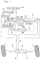
- FIG. 1 a block diagram of Fig. 1 showing a controlling apparatus in a first embodiment of the present invention
- right and left rear wheels 1 are turned by an electric motor 4 according to a rear wheel steering angle instructing signal 6 output to a motor driver 3 from a controlling device 2 which controls a steering angle of rear wheels of a four-wheel steering vehicle.
- a reduction gear 5 is present between the electric motor 4 and rear wheels 1 to amplify a torque.
- the controlling device 2 is constituted by an operating device 16 which determines a target steering angle of rear wheels to an input value from each of a speed sensor 7, a steering wheel angle sensor 8 and a rear wheel position detector 10 and, also determines the above-referred rear wheel steering angle instructing signal 6 and, interface circuits 12, 14, 15 of the respective sensors.
- the operating device 16 is comprised of a desired steering angle setting device 22 for setting a desired steering angle of the rear wheels, a comparator 26 and a current instructing value setting device 23 which consists of a comparator 23a and couplers 23b, 23c.
- the first interface circuit 14 mounted to the electric motor 4 which converts a value of the position detector 10 to a digital value thereby to obtain the current position of the electric motor 4, steering wheel angle sensor 8, interface circuits 12, 13 for converting a detecting signal of the yaw rate sensor 9 to a digital value
- second interface circuit 15 which feeds a current instructing value 6 to the motor driver 3 and operating device 16 which processes a desired steering angle of the rear wheels, the current instructing value 6 and detects a cycle of the speed sensor 7.
- a deviation between a target steering angle of the rear wheels determined by the steering wheel angle, yaw rate and vehicle velocity, i.e., a target steering angle of the electric motor 4 mounted in the rear wheels 1 and, the current position of the electric motor 4 is processed for every sampling cycle.
- the deviation is integrated for every sampling cycle.
- a value obtained by multiplying the deviation with Kp is added to a value obtained by multiplying an integrating value of the deviation with a coefficient Ki. Then, a value obtained by multiplying a velocity of the electric motor 4 obtained through reduction of the current position and a current position one cycle before with Kd is subtracted from a value obtained by multiplying the above adding value with a function f(V) of the vehicle velocity, which is output as the current instructing value 6 to the motor driver 3 via the second interface circuit 15.
- the function f(V) is a constant proportional to the vehicle velocity. In other words, as the vehicle velocity is increased while the deviation is the same, the current instructing value 6 to the motor driver 3 is increased, thereby enhancing the controlling property of the electric motor 4.
- Fig. 1(a) is a graph showing the relation between vehicle velocity and function f(V), wherein f(V) is increased in proportion to the vehicle velocity.
- Fig. 2 is a block diagram of a controlling apparatus according to a modification of the above embodiment.
- the modified controlling apparatus is fundamentally equal to the apparatus of Fig. 1 in its structure, but is provided with a K1 (same phase) and a K2 (reverse phase) circuits in the f(V) circuit within the operating device 16.
- Whether the rear wheels are turned in the same phase or reverse phase to the front wheels is detected by a phase detector from a steering wheel angle and a motor (rear wheel) angle.
- a gain K1 or K2 is multiplied for the same phase time or for the reverse phase time.
- a deviation between a target steering angle of the rear wheels determined by the steering wheel angle, yaw rate and vehicle velocity, i.e., a target steering angle of the electric motor 4 mounted in the rear wheels 1 and the current position of the electric motor 4 is processed for every sampling cycle.
- the deviation is integrated for every sampling cycle.
- a value obtained by multiplying the deviation with Kp is added to a value obtained by multiplying an integrating value with the coefficient Ki. Thereafter, in the case where the front (not shown) and rear wheels are turned in the same phase, a value obtained by multiplying the velocity of the electric motor obtained through reduction of the current position and a current position one cycle before of the electric motor with Kd is subtracted from a value obtained by multiplying the adding value with K1. On the other hand, if the front and rear wheels are turned in the reverse phase, the value is subtracted from a value obtained by multiplying the adding value with K2. The resultant value is output as the current instructing value 6 to the motor driver 3 via the second interface circuit 15.
- K1 is set larger than K2. That is, when the rear wheels are turned in the reverse phase to the front wheels in proportion to the size of the steering wheel angle, the electric motor gets delayed in response. If the rear wheels are turned in the same phase as the front wheels in proportion to the size of the yaw rate, the responding capability of the rear wheels is improved.
- the fundamental concept of the above embodiment is made effective in the other controlling methods as well even when the responding capability of the electric motor is changed depending on the vehicle velocity or when the rear wheels are turned in the reverse or same phase to the front wheels.
- the responding speed of the electric motor is decreased to suppress the power consumption.
- the responding capability of the rear wheels is changed between when the rear wheels are turned in the reverse phase to the front wheels in proportion to the steering wheel angle and when the rear wheels are turned in the same phase as the front wheels in proportion to the yaw rate, the feedback loop for the rear wheel steering system to feed back the yaw rate is retained stable, whereby the advancing direction or course of the rear wheels can be corrected stably.
Landscapes
- Engineering & Computer Science (AREA)
- Chemical & Material Sciences (AREA)
- Combustion & Propulsion (AREA)
- Transportation (AREA)
- Mechanical Engineering (AREA)
- Physics & Mathematics (AREA)
- Mathematical Physics (AREA)
- Theoretical Computer Science (AREA)
- Steering Control In Accordance With Driving Conditions (AREA)
- Steering-Linkage Mechanisms And Four-Wheel Steering (AREA)
Claims (2)
- Dispositif de commande destiné à commander l'angle de braquage des roues arrière (1) d'un véhicule à quatre roues directrices, comprenant :
un capteur de vitesse du véhicule (7) pour détecter la vitesse du véhicule ;
un capteur de taux de lacet (9) pour détecter le taux de lacet ;
un capteur d'angle de volant de direction (8) pour détecter l'angle de braquage du volant de direction ;
un contrôleur (2) pour sortir un signal d'ordre d'angle de braquage de roues arrière en résponse aux signaux desdits capteurs (7, 8, 9) ; et
un moteur électrique (4) pour braquer les roues arrière (1) sur la base dudit signal d'ordre d'angle de braquage des roues arrière , ledit moteur électrique (4) étant prévu avec un détecteur de position (10) ; ledit contrôleur (2) étant prévu avec un premier circuit d'interface (14) pour obtenir la position actuelle dudit moteur électrique (4) à partir dudit détecteur de position (10), une unité d'opération (16) pour calculer un angle de braquage désiré desdites roues arrière (1) à partir de la valeur de sortie desdits capteurs (7, 8, 9) et pour calculer l'écart entre la position désirée et la position actuelle dudit moteur électrique (4), et un second circuit d'interface (15) pour délivrer un ordre de courant à une unité de commande de moteur (3) à partir de ladite unité d'opération (16), caractérisé en ce que, dans ladite unité d'opération (16), une valeur obtenue par l'intermédiaire de l'opération différentielle de la position actuelle du moteur électrique (4) est soustraite d'une valeur obtenue en multipliant une valeur obtenue par l'intermédiaire de l'opération proportionnelle de l'écart et une valeur obtenue par l'intermédiaire de l'opération intégrale de l'écart avec une valeur proportionnelle à la vitesse du véhicule, de sorte que la valeur obtenue soit sortie comme une valeur d'ordre de courant (6) vers ladite unité de commande du moteur (3) par l'intermédiaire dudit second circuit d'interface (15). - Dispositif de commande selon la revendication 1, dans lequel l'écart entre la position désirée et la position actuelle dudit moteur électrique (4) est traité dans l'unité d'opération (16) et dans lequel une valeur obtenue par la différentiation de la position actuelle dudit moteur électrique (4) est soustraite d'une valeur obtenue en multipliant une valeur d'addition, d'une valeur de proportionnalité de l'écart et d'une valeur d'intégration de l'écart, avec une constante de proportionnalité qui est différente pour le cas de la phase inverse ou par rapport au cas de la même phase, et est sortie comme la valeur d'ordre de courant (6) vers ledit moteur électrique (4) par l'intermédiaire dudit second circuit d'interface (15).
Applications Claiming Priority (6)
| Application Number | Priority Date | Filing Date | Title |
|---|---|---|---|
| JP212861/90 | 1990-08-10 | ||
| JP2212861A JPH0495576A (ja) | 1990-08-10 | 1990-08-10 | 四輪操舵車の後輪操舵角制御装置 |
| JP2409044A JPH04231265A (ja) | 1990-12-28 | 1990-12-28 | 四輪操舵車の後輪操舵角制御装置 |
| JP409044/90 | 1990-12-28 | ||
| JP3069708A JPH04306169A (ja) | 1991-04-02 | 1991-04-02 | 四輪操舵車の後輪操舵角制御装置 |
| JP69708/91 | 1991-04-02 |
Publications (3)
| Publication Number | Publication Date |
|---|---|
| EP0470630A2 EP0470630A2 (fr) | 1992-02-12 |
| EP0470630A3 EP0470630A3 (en) | 1993-12-15 |
| EP0470630B1 true EP0470630B1 (fr) | 1996-02-07 |
Family
ID=27300118
Family Applications (1)
| Application Number | Title | Priority Date | Filing Date |
|---|---|---|---|
| EP91113375A Expired - Lifetime EP0470630B1 (fr) | 1990-08-10 | 1991-08-09 | Appareil de commande de l'angle de direction des roues arrières d'un véhicule à quatre roues directrices |
Country Status (4)
| Country | Link |
|---|---|
| US (2) | US5274555A (fr) |
| EP (1) | EP0470630B1 (fr) |
| KR (1) | KR960007419B1 (fr) |
| DE (1) | DE69116951T2 (fr) |
Families Citing this family (25)
| Publication number | Priority date | Publication date | Assignee | Title |
|---|---|---|---|---|
| JPH05229444A (ja) * | 1992-02-05 | 1993-09-07 | Toyota Motor Corp | 4輪操舵車の後輪操舵制御装置 |
| US5524079A (en) * | 1992-09-01 | 1996-06-04 | Matsushita Electric Industrial Co., Ltd. | Rear wheel steering angle controlling apparatus of four-wheel steering vehicle |
| JP3091038B2 (ja) * | 1992-12-02 | 2000-09-25 | 本田技研工業株式会社 | 前後輪操舵車両の制御装置 |
| JP2982595B2 (ja) * | 1993-12-27 | 1999-11-22 | 日産自動車株式会社 | 車両用実舵角制御装置 |
| EP0663333B1 (fr) * | 1994-01-14 | 1998-12-23 | Matsushita Electric Industrial Co., Ltd. | Dispositif de commande d'angle de direction |
| JP2686042B2 (ja) * | 1994-03-02 | 1997-12-08 | 本田技研工業株式会社 | 前後輪操舵車両の制御装置 |
| DE19502858C1 (de) * | 1995-01-30 | 1996-07-11 | Siemens Ag | Verfahren und Schaltungsanordnung zum Kompensieren der Signalfehler eines Giergeschwindigkeitssensors |
| JP3225790B2 (ja) * | 1995-06-09 | 2001-11-05 | トヨタ自動車株式会社 | 車両挙動制御装置 |
| JP2004144221A (ja) * | 2002-10-25 | 2004-05-20 | Advics:Kk | 自動クラッチ制御装置 |
| JP4039210B2 (ja) * | 2002-10-29 | 2008-01-30 | トヨタ自動車株式会社 | 車輌の運動制御装置 |
| JP4269994B2 (ja) * | 2004-03-25 | 2009-05-27 | 三菱ふそうトラック・バス株式会社 | 車両のステア特性制御装置 |
| JP2005271822A (ja) * | 2004-03-25 | 2005-10-06 | Mitsubishi Fuso Truck & Bus Corp | 車両の自動減速制御装置 |
| FR2887841B1 (fr) * | 2005-06-30 | 2007-08-24 | Renault Sas | Systeme et procede de commande de braquage des roues arriere directrices embarque a bord d'un vehicule automobile a quatre roues directrices |
| EP1785809A1 (fr) * | 2005-11-14 | 2007-05-16 | Texas Instruments Inc. | Mode veille pour gestion d'alimentation |
| CN101401089B (zh) * | 2006-01-11 | 2014-03-12 | 费希尔-罗斯蒙德系统公司 | 具有通过无线网络的预测现场设备响应时间的控制系统 |
| US7881841B2 (en) * | 2006-12-28 | 2011-02-01 | Caterpillar Inc. | Motion-control system |
| JP5383809B2 (ja) | 2008-09-25 | 2014-01-08 | フィッシャー−ローズマウント システムズ,インコーポレイテッド | 障害要因警報及びバッテリ電力低下警報を有する無線メッシュネットワーク |
| JP5325708B2 (ja) * | 2009-03-30 | 2013-10-23 | 本田技研工業株式会社 | 車両の後輪操舵制御装置 |
| US10645628B2 (en) * | 2010-03-04 | 2020-05-05 | Rosemount Inc. | Apparatus for interconnecting wireless networks separated by a barrier |
| US8737244B2 (en) | 2010-11-29 | 2014-05-27 | Rosemount Inc. | Wireless sensor network access point and device RF spectrum analysis system and method |
| US20130005372A1 (en) | 2011-06-29 | 2013-01-03 | Rosemount Inc. | Integral thermoelectric generator for wireless devices |
| JP2014085880A (ja) * | 2012-10-24 | 2014-05-12 | Jtekt Corp | Pid制御システム |
| US9969425B2 (en) | 2013-05-20 | 2018-05-15 | Robert Bosch Gmbh | Rear wheel steering control |
| US11685434B2 (en) | 2021-01-11 | 2023-06-27 | Hyundai Mobis Co., Ltd. | Method for rear steering control of a vehicle |
| KR102745870B1 (ko) * | 2023-01-17 | 2024-12-23 | 에이치엘만도 주식회사 | 후륜 조향 장치 및 이의 제어 방법 |
Family Cites Families (37)
| Publication number | Priority date | Publication date | Assignee | Title |
|---|---|---|---|---|
| JPS60161256A (ja) * | 1984-01-31 | 1985-08-22 | Nissan Motor Co Ltd | 車両の補助操舵方法 |
| DE3661472D1 (en) * | 1985-04-13 | 1989-01-26 | Nissan Motor | Vehicle control system for controlling side slip angle and yaw rate gain |
| JPS61241274A (ja) * | 1985-04-19 | 1986-10-27 | Kayaba Ind Co Ltd | 後輪操舵装置 |
| JPS61295175A (ja) * | 1985-06-22 | 1986-12-25 | Mazda Motor Corp | 車両の4輪操舵装置 |
| JPS628869A (ja) * | 1985-07-08 | 1987-01-16 | Mazda Motor Corp | 車両の4輪操舵装置 |
| JPS62175263A (ja) * | 1986-01-30 | 1987-07-31 | Hitachi Ltd | 電動パワ−ステアリング制御装置 |
| JPH0774000B2 (ja) * | 1986-02-07 | 1995-08-09 | マツダ株式会社 | 車両の4輪操舵装置 |
| KR900005710B1 (ko) * | 1986-04-29 | 1990-08-06 | 미쓰비시전기 주식회사 | 모터구동식 동력조향 제어장치 |
| US4836319A (en) * | 1986-07-22 | 1989-06-06 | Nippondenso Co., Ltd. | Steering control apparatus for motor vehicles |
| JPS6341282A (ja) * | 1986-08-05 | 1988-02-22 | Nissan Motor Co Ltd | 車両用実舵角制御装置 |
| JP2518245B2 (ja) * | 1987-02-03 | 1996-07-24 | 日本電装株式会社 | 車両用後輪操舵装置 |
| DE3861868D1 (de) * | 1987-02-03 | 1991-04-11 | Toyoda Chuo Kenkyusho Kk | Steuervorrichtung fuer das lenken der raeder eines fahrzeugs. |
| JPH06506B2 (ja) * | 1987-03-04 | 1994-01-05 | 三菱電機株式会社 | モ−タ駆動式パワ−ステアリング制御方法 |
| CA1320551C (fr) * | 1987-03-09 | 1993-07-20 | Shuji Shiraishi | Dispositif anti-lacet |
| JP2578142B2 (ja) * | 1987-11-30 | 1997-02-05 | 日産自動車株式会社 | 車両の補助操舵装置 |
| JP2679803B2 (ja) * | 1988-04-08 | 1997-11-19 | マツダ株式会社 | 車両の後輪操舵装置 |
| JP2689335B2 (ja) * | 1988-05-18 | 1997-12-10 | 自動車機器株式会社 | 4輪操舵システム駆動系のセルフチエツク方法 |
| JP2594816B2 (ja) * | 1988-06-02 | 1997-03-26 | ダイハツ工業株式会社 | 自動車の四輪操舵装置および四輪操舵方法 |
| DE3819849A1 (de) * | 1988-06-10 | 1989-12-14 | Siemens Ag | Prozessrechnergesteuerte aktive hinterachsenkinematik eines kfz |
| US4828061A (en) * | 1988-06-27 | 1989-05-09 | General Motors Corporation | Closed-loop four wheel steering system having dual response rate rear steering |
| JP2549708B2 (ja) * | 1988-07-05 | 1996-10-30 | 日産自動車株式会社 | 4輪操舵車両の後輪操舵装置 |
| DE68925130T2 (de) * | 1988-07-11 | 1996-05-09 | Koyo Seiko Co | Servolenkung |
| EP0350817B1 (fr) * | 1988-07-11 | 1995-04-19 | Koyo Seiko Co., Ltd. | Direction assistée par moteur |
| US5001637A (en) * | 1988-08-01 | 1991-03-19 | Honda Giken Kogyo Kabushiki Kaisha | Steering wheel turning angle detector and method for controlling yawing for vehicle |
| US5064013A (en) * | 1988-09-02 | 1991-11-12 | Erwin Lenz | Hydraulically driven electrically powered vehicle with energy recapture |
| US5313389A (en) * | 1988-09-13 | 1994-05-17 | Aisin Seiki Kabushiki Kaisha | Fail-safe mechanism for vehicle stability augmentation steering system |
| US5159553A (en) * | 1988-09-13 | 1992-10-27 | Aisin Seiki Kabushiki Kaisha | Steering control apparatus |
| US5156229A (en) * | 1988-09-13 | 1992-10-20 | Aisin Seiki Kabushiki Kaisha | Steering control apparatus |
| JP2641743B2 (ja) * | 1988-09-22 | 1997-08-20 | 本田技研工業株式会社 | 四輪操舵車の後輪制御方法 |
| GB8909074D0 (en) * | 1989-04-21 | 1989-06-07 | Lotus Group Plc | Vehicle control system |
| JP2805341B2 (ja) * | 1989-06-27 | 1998-09-30 | 三菱自動車工業株式会社 | 四輪操舵装置 |
| JPH0354076A (ja) * | 1989-07-20 | 1991-03-08 | Matsushita Electric Ind Co Ltd | 四輪操舵車の後輪操舵角制御装置 |
| US5145022A (en) * | 1989-11-15 | 1992-09-08 | Daihatsu Motor Co., Ltd. | System and method for pivotally controlling vehicle rear wheels |
| DE4114165C2 (de) * | 1990-05-02 | 1995-04-20 | Nissan Motor | Lenksteuervorrichtung für ein Räderfahrzeug |
| DE69109185T2 (de) * | 1990-06-04 | 1996-01-11 | Nippon Denso Co | Signalverarbeitungsschaltung für Giergeschwindigkeitssensor. |
| JP2531917B2 (ja) * | 1993-01-23 | 1996-09-04 | 有限会社レンタルセンター | 梯 子 |
| JP3873634B2 (ja) * | 2001-02-28 | 2007-01-24 | 株式会社日立製作所 | 風力発電システム |
-
1991
- 1991-08-09 US US07/743,225 patent/US5274555A/en not_active Expired - Lifetime
- 1991-08-09 DE DE69116951T patent/DE69116951T2/de not_active Expired - Fee Related
- 1991-08-09 EP EP91113375A patent/EP0470630B1/fr not_active Expired - Lifetime
- 1991-08-10 KR KR1019910013806A patent/KR960007419B1/ko not_active Expired - Fee Related
-
1995
- 1995-02-22 US US08/392,626 patent/US5502639A/en not_active Expired - Fee Related
Also Published As
| Publication number | Publication date |
|---|---|
| KR920004225A (ko) | 1992-03-27 |
| US5274555A (en) | 1993-12-28 |
| US5502639A (en) | 1996-03-26 |
| KR960007419B1 (ko) | 1996-05-31 |
| EP0470630A3 (en) | 1993-12-15 |
| DE69116951T2 (de) | 1996-10-02 |
| DE69116951D1 (de) | 1996-03-21 |
| EP0470630A2 (fr) | 1992-02-12 |
Similar Documents
| Publication | Publication Date | Title |
|---|---|---|
| US5502639A (en) | Controlling apparatus of steering angle of rear wheels of four-wheel steering vehicle | |
| US5294871A (en) | Electric motor control system | |
| US5627754A (en) | Method for controlling a front and rear wheel steering vehicle | |
| US5345155A (en) | Control system for electric vehicle | |
| US5448481A (en) | Control system for a front and rear wheel steering vehicle | |
| US11975775B2 (en) | Steering control device and steering control method | |
| US5561603A (en) | Vehicle rear wheel steering angle controlling apparatus having means for reducing vehicle-speed-based change in the angle, when steering wheel is not operated | |
| JPH0577626A (ja) | 車輪のトー角制御装置 | |
| US6671597B2 (en) | Electric power steering controller | |
| JPH01109173A (ja) | 4輪操舵システム | |
| JP2518245B2 (ja) | 車両用後輪操舵装置 | |
| JPS6299213A (ja) | 4輪駆動車の駆動力配分制御装置 | |
| WO1994020325A1 (fr) | Dispositif de commande de la conduite d'un vehicule, en particulier d'une chaise roulante, et vehicule pourvu d'un tel dispositif de commande | |
| JPH072130A (ja) | 後輪操舵装置の制御方法 | |
| JP7759919B2 (ja) | 運転支援装置および運転支援を行う方法 | |
| JPH0811544B2 (ja) | 車両用操舵系制御装置 | |
| JPH037675A (ja) | 四輪操舵装置 | |
| JP2533491B2 (ja) | 制御主導型自動車 | |
| JPH04231265A (ja) | 四輪操舵車の後輪操舵角制御装置 | |
| JPH065950Y2 (ja) | 車両の後輪舵角制御装置 | |
| JPH06156301A (ja) | 四輪操舵車の後輪操舵角制御装置 | |
| JPH03148377A (ja) | 四輪操舵装置 | |
| JPH04306169A (ja) | 四輪操舵車の後輪操舵角制御装置 | |
| JPH05147551A (ja) | 四輪操舵車の後輪操舵角制御装置 | |
| JP2523187B2 (ja) | 車両の舵角制御装置 |
Legal Events
| Date | Code | Title | Description |
|---|---|---|---|
| PUAI | Public reference made under article 153(3) epc to a published international application that has entered the european phase |
Free format text: ORIGINAL CODE: 0009012 |
|
| 17P | Request for examination filed |
Effective date: 19910809 |
|
| AK | Designated contracting states |
Kind code of ref document: A2 Designated state(s): DE FR GB IT |
|
| PUAL | Search report despatched |
Free format text: ORIGINAL CODE: 0009013 |
|
| PUAF | Information related to the publication of a search report (a3 document) modified or deleted |
Free format text: ORIGINAL CODE: 0009199SEPU |
|
| AK | Designated contracting states |
Kind code of ref document: A3 Designated state(s): DE FR GB IT |
|
| D17D | Deferred search report published (deleted) | ||
| PUAL | Search report despatched |
Free format text: ORIGINAL CODE: 0009013 |
|
| AK | Designated contracting states |
Kind code of ref document: A3 Designated state(s): DE FR GB IT |
|
| 17Q | First examination report despatched |
Effective date: 19941215 |
|
| GRAA | (expected) grant |
Free format text: ORIGINAL CODE: 0009210 |
|
| AK | Designated contracting states |
Kind code of ref document: B1 Designated state(s): DE FR GB IT |
|
| ITF | It: translation for a ep patent filed | ||
| REF | Corresponds to: |
Ref document number: 69116951 Country of ref document: DE Date of ref document: 19960321 |
|
| ET | Fr: translation filed | ||
| PLBE | No opposition filed within time limit |
Free format text: ORIGINAL CODE: 0009261 |
|
| STAA | Information on the status of an ep patent application or granted ep patent |
Free format text: STATUS: NO OPPOSITION FILED WITHIN TIME LIMIT |
|
| 26N | No opposition filed | ||
| PGFP | Annual fee paid to national office [announced via postgrant information from national office to epo] |
Ref country code: GB Payment date: 19990804 Year of fee payment: 9 |
|
| PGFP | Annual fee paid to national office [announced via postgrant information from national office to epo] |
Ref country code: DE Payment date: 19990809 Year of fee payment: 9 |
|
| PGFP | Annual fee paid to national office [announced via postgrant information from national office to epo] |
Ref country code: FR Payment date: 19990810 Year of fee payment: 9 |
|
| PG25 | Lapsed in a contracting state [announced via postgrant information from national office to epo] |
Ref country code: GB Free format text: LAPSE BECAUSE OF NON-PAYMENT OF DUE FEES Effective date: 20000809 |
|
| GBPC | Gb: european patent ceased through non-payment of renewal fee |
Effective date: 20000809 |
|
| PG25 | Lapsed in a contracting state [announced via postgrant information from national office to epo] |
Ref country code: FR Free format text: LAPSE BECAUSE OF NON-PAYMENT OF DUE FEES Effective date: 20010430 |
|
| PG25 | Lapsed in a contracting state [announced via postgrant information from national office to epo] |
Ref country code: DE Free format text: LAPSE BECAUSE OF NON-PAYMENT OF DUE FEES Effective date: 20010501 |
|
| REG | Reference to a national code |
Ref country code: FR Ref legal event code: ST |
|
| PG25 | Lapsed in a contracting state [announced via postgrant information from national office to epo] |
Ref country code: IT Free format text: LAPSE BECAUSE OF NON-PAYMENT OF DUE FEES;WARNING: LAPSES OF ITALIAN PATENTS WITH EFFECTIVE DATE BEFORE 2007 MAY HAVE OCCURRED AT ANY TIME BEFORE 2007. THE CORRECT EFFECTIVE DATE MAY BE DIFFERENT FROM THE ONE RECORDED. Effective date: 20050809 |