EP0472100A2 - Lampe à décharge à haute pression - Google Patents
Lampe à décharge à haute pression Download PDFInfo
- Publication number
- EP0472100A2 EP0472100A2 EP19910113606 EP91113606A EP0472100A2 EP 0472100 A2 EP0472100 A2 EP 0472100A2 EP 19910113606 EP19910113606 EP 19910113606 EP 91113606 A EP91113606 A EP 91113606A EP 0472100 A2 EP0472100 A2 EP 0472100A2
- Authority
- EP
- European Patent Office
- Prior art keywords
- discharge lamp
- pressure discharge
- lamp according
- niobium
- coating
- Prior art date
- Legal status (The legal status is an assumption and is not a legal conclusion. Google has not performed a legal analysis and makes no representation as to the accuracy of the status listed.)
- Withdrawn
Links
Images

Classifications
-
- H—ELECTRICITY
- H01—ELECTRIC ELEMENTS
- H01J—ELECTRIC DISCHARGE TUBES OR DISCHARGE LAMPS
- H01J61/00—Gas-discharge or vapour-discharge lamps
- H01J61/02—Details
- H01J61/36—Seals between parts of vessels; Seals for leading-in conductors; Leading-in conductors
- H01J61/366—Seals for leading-in conductors
Definitions
- the invention is based on a high-pressure discharge lamp according to the preamble of claim 1.
- Typical power levels are 100 - 250 W.
- a structure is known from the high-pressure sodium lamps in which the ceramic discharge vessel consists of Al2O3, to which small additions of other oxides may be added. At the ends is a niobium tube, the thermal expansion coefficient of which is well adapted to the Al2O3 ceramic, fitted into a ceramic stopper and sealed by a glass solder.
- the main problem with the transfer of this technology to lamps with metal halide filling is the highly corrosive effect of the metal halides on the niobium tubes and the glass solder.
- special glass solders as described, for example, in EP-A 60 582 and EP-A 230 080 are described, the life of such lamps has so far been limited to short burning times.
- the invention allows to use well-known ceramic materials (esp. Al2O3, possibly with additives of other oxides) and to use a known implementation technique.
- An approximately cylindrical ceramic stopper has a central opening through which a tube or a solid niobium wire pin is passed.
- halide-resistant material in particular tungsten, molybdenum, Al2O3 or platinum.
- the layer thickness is advantageously 2-5 ⁇ m. With a smaller layer thickness, it is not reliably ensured that the lead-through area is completely and evenly covered. A thicker layer tends to flake and internal tensions when subjected to changes in temperature. With molybdenum and platinum, the layer thickness is not quite as critical, since these materials have a thermal expansion coefficient closer to niobium than tungsten.
- the layer is applied to the niobium feed line by sputtering. The thickness of the layer should be as uniform as possible ( ⁇ 0.5 ⁇ m) so that the sealing bond cannot be affected by micropores and cracks in the coating.
- the layer can completely cover the niobium feed line, in particular including the welding point to the tungsten electrode shaft.
- tungsten should be used as the coating material because it has a very high melting point and a very low vapor pressure, so that it evaporates less than other materials at the high temperatures at the electrode.
- the coated niobium surface When melting, the coated niobium surface is dissolved less by the glass solder than the pure, uncoated surface. This can be seen on the one hand by comparing the wetting angle of the glass solder on the niobium feed line. With an uncoated niobium lead, the wetting angle of a glass solder drop is less than 30 °. With a coated niobium feed line, it is approximately 60 °.
- the color of the melt in a coated niobium feed line is lighter and more similar to ceramic.
- a niobium tube for such a composite system because of its elasticity.
- a solid or hollow niobium pin can be removed from the attack of the halides even more effectively. This happens because the pin is flush with the inside edge of the plug. Even better results can be achieved if the pin is inserted deeply into the through opening of the plug.
- the insertion depth is preferably approximately 3 mm.
- the pin advantageously has a diameter of 1-1.5 mm. With this arrangement, it is particularly favorable to also cover the section of the electrode shaft running within the opening with tungsten or the like. to coat. Overall, this arrangement not only shortens the lead-through area, but also minimizes the contact surface on the niobium stick, so that this more than outweighs the disadvantage of lower elasticity compared to a niobium tube.
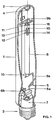
- a metal halide discharge lamp with an output of 150 W is shown schematically in FIG. It consists of a cylindrical (or also elliptical) outer bulb 1 made of tempered glass, which is closed at one end with a cap 2, while a screw base 3 is attached at the other end. In the area of the dome 2, a nipple 4 is formed to hold a frame 5. The latter has two power supply lines 6, which are melted from one another in an insulated manner by means of a plate melting 7 into the base-side end of the outer bulb 1.
- the frame 5 holds an axially arranged in the outer bulb 1 cylindrical (or bulged) discharge vessel 8 made of Al2O3 ceramic, in each of which a power supply 6 via a conductor 9 with a niobium bushing (supply line) 10, each in a stopper 11 on End of the discharge vessel is fitted, is connected.
- a power supply 6 via a conductor 9 with a niobium bushing (supply line) 10, each in a stopper 11 on End of the discharge vessel is fitted, is connected.
- One of the conductors, 9a is formed by the end of one feed wire 6a, while the other conductor is a leaf spring part 9b, which is welded to a section of the other power supply 6b designed as a rod.
- This arrangement takes into account the thermal expansion during lamp operation.
- the section formed as a solid metal rod extends to the top 2 and is bent there into a partial circle which encompasses the nipple 4.
- the two lead-throughs or feed lines 10 made of niobium each hold electrodes 12 on the discharge side, consisting of an electrode shaft 13 and a helix 14 pushed on at the discharge end.
- the discharge vessel is filled with an inert ignition gas, e.g. Argon, from mercury and additives to metal halides.
- the cylindrical outer bulb of the lamp is pinched and capped on two sides.
- the axially arranged discharge vessel is bulged in the middle, while its two ends are tubular.
- the two niobium bushings are connected to the bases at the two ends of the outer bulb via short current leads. A rack is not required.
- the melting area at one end of the discharge vessel 8 is shown in detail in FIG.
- the discharge vessel 8 has a wall thickness of 1.2 mm at both ends.
- a niobium wire pin 16 with a length of 12 mm and a diameter of 1.2 mm is fitted into an axial opening 15 of the plug. It is inserted into the opening 15 so that a channel-like recess 17 of approximately 2 mm in length remains in the region of the opening 15 on the discharge side.
- the wire pin is covered over its entire length with a tungsten layer 19 with a thickness of 2 ⁇ m.
- the wire pin 16 is connected gas-tight to the plug 11 by a corrosion-resistant glass solder 20, for example a mixture of the oxides of aluminum, titanium and one or more rare earths.
- the area of the electrode shaft 13 located in the recess 17 (about 2 mm in length) is also provided with the coating 19, so that in particular the area of the weld is additionally protected.
- the lamp is filled through the second, still unsealed opening. Closing the first opening beforehand is not a problem.
- the glass solder is applied to the outside of the bushing, is heated and runs into the capillary between the stopper and bushing when it melts.
- the gas filling opposes the running in of the glass solder, with the result that the wire pin is not always completely covered by glass solder after solidification.
- the second opening is only sealed after filling.
- the number of early failures is directly correlated with the quality of this second melting in lamps without a coating. A significant improvement can be seen in lamps with coated wire pins, which are also used in a recessed manner. Because the execution area is shortened, its coverage is included Glass solder more complete. The proportion of early failures is reduced by 80%.
- FIG. 3 shows a largely identical second exemplary embodiment, elements of the same construction having the same reference numbers.
- the lead-through area 18, which is covered with glass solder 20, extends over the entire length of the opening 15.
- the entire niobium wire pin / electrode shaft / coil system is covered with a 2 ⁇ m thick protective layer 19.
- only tungsten is suitable as the coating material because the temperature load in the vicinity of the electrode tip is very high and the protective layer is prevented from evaporating by the extremely high melting temperature of the tungsten.
- the first exemplary embodiment is equally suitable for the melting, while the second can preferably be used for the melting of the one which is sealed before the discharge vessel is filled.
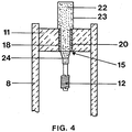
- a niobium tube 22 is realized by a niobium tube 22, as is the case is already known from high pressure sodium lamps.
- the same elements again have the same reference numbers.
- the niobium tube 22 is covered over its entire length by a molybdenum coating 23 with a thickness of 5 ⁇ m.
- the tapered discharge-side end 24 protrudes into the discharge space and carries the uncoated electrode 12 on its end face.
- This lamp is filled in a manner known per se either before or after the second bushing has melted, an opening in the tube 22 being formed for this purpose in the latter case. The problem of pressure equalization is then irrelevant.
- the invention is not restricted to the exemplary embodiments shown.
- the pipe end is so narrow that the electrical feed line (feedthrough) is fitted into the pipe end without a plug.
- a different melting system can be used for each of the two ends of the discharge vessel, a combination of the exemplary embodiments described here or a combination of a melting system according to the invention with melting systems known per se being possible.
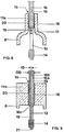
- Exemplary embodiments without a plug are shown in FIGS. 5 and 6: Instead of a solid wire pin, a hollow pin with approximately the same dimensions can also be used (Fig. 5).
- the hollow pin 16a is closed on the discharge side (16c). In this way, the advantages of a niobium tube (elasticity) and a wire pin (shortened lead-through area) can be advantageously combined.
- the bore 16b of the hollow pin has a diameter ID which corresponds approximately to the wall thickness of the pin, that is to say half the difference between the outer diameter OD and the inner diameter ID.
- the advantages of the elastic tube can be combined with those of the pin, which enables a shortened implementation area.
- a discharge vessel is used which has inward-facing projections 11b at the ends, which are an integral part of the vessel.
- FIG. 6 An embodiment similar to FIG. 2 is shown in FIG. 6.
- the discharge vessel 8 ' is bulged in the middle (e.g. cylindrical or barrel-shaped) and has at the ends narrowed sections 11a which define the opening 15 and the passage area 18.
- the scope of the protective coating is not tied to the type and depth of use of the niobium feedthrough, as shown in the exemplary embodiments. It is essential that the protective coating comprises at least the lead-through area 18.
Landscapes
- Vessels And Coating Films For Discharge Lamps (AREA)
Applications Claiming Priority (2)
| Application Number | Priority Date | Filing Date | Title |
|---|---|---|---|
| DE9012200U | 1990-08-24 | ||
| DE9012200U DE9012200U1 (de) | 1990-08-24 | 1990-08-24 | Hochdruckentladungslampe |
Publications (2)
| Publication Number | Publication Date |
|---|---|
| EP0472100A2 true EP0472100A2 (fr) | 1992-02-26 |
| EP0472100A3 EP0472100A3 (en) | 1992-06-17 |
Family
ID=6856824
Family Applications (1)
| Application Number | Title | Priority Date | Filing Date |
|---|---|---|---|
| EP19910113606 Withdrawn EP0472100A3 (en) | 1990-08-24 | 1991-08-13 | High-pressure discharge lamp |
Country Status (3)
| Country | Link |
|---|---|
| EP (1) | EP0472100A3 (fr) |
| JP (1) | JPH0499662U (fr) |
| DE (1) | DE9012200U1 (fr) |
Cited By (12)
| Publication number | Priority date | Publication date | Assignee | Title |
|---|---|---|---|---|
| EP0536609A1 (fr) * | 1991-10-11 | 1993-04-14 | Patent-Treuhand-Gesellschaft für elektrische Glühlampen mbH | Lampe à décharge à haute pression |
| EP0570772A1 (fr) * | 1992-05-18 | 1993-11-24 | Patent-Treuhand-Gesellschaft für elektrische Glühlampen mbH | Lampe à décharge à haute pression |
| EP0587238A1 (fr) * | 1992-09-08 | 1994-03-16 | Koninklijke Philips Electronics N.V. | Lampe à décharge à haute pression |
| WO1994006727A1 (fr) * | 1992-09-16 | 1994-03-31 | Patent-Treuhand-Gesellschaft für elektrische Glühlampen mbH | Elements d'etancheite pour tubes a regime d'arc en alumine et procede pour leur fabrication |
| EP0652586A1 (fr) * | 1993-11-10 | 1995-05-10 | Patent-Treuhand-Gesellschaft für elektrische Glühlampen mbH | Lampe à décharge à halogénure de métal avec récipient de décharge en céramique et son procédé de fabrication |
| WO1995028732A1 (fr) * | 1994-04-13 | 1995-10-26 | Philips Electronics N.V. | Lampe a halogene-metal a haute pression |
| US5592049A (en) * | 1993-02-05 | 1997-01-07 | Patent-Treuhand-Gesellschaft Fuer Elektrische Gluehlampen Mbh | High pressure discharge lamp including directly sintered feedthrough |
| US5698946A (en) * | 1992-06-05 | 1997-12-16 | U.S. Philips Corporation | Electric lamp having a protective skin on end portions of the current conductors |
| US6139386A (en) * | 1995-01-13 | 2000-10-31 | Ngk Insulators, Ltd. | High pressure discharge lamp with an improved sealing system and method of producing the same |
| WO2006007177A3 (fr) * | 2004-06-30 | 2006-07-13 | Gen Electric | Systeme et procede de conception d'une lame de projecteur |
| WO2006077516A3 (fr) * | 2005-01-19 | 2007-10-11 | Koninkl Philips Electronics Nv | Lampe a decharge haute pression |
| WO2010063517A3 (fr) * | 2008-12-05 | 2010-09-16 | Osram Gesellschaft mit beschränkter Haftung | Lampe à décharge à arc court et son procédé de fabrication |
Family Cites Families (3)
| Publication number | Priority date | Publication date | Assignee | Title |
|---|---|---|---|---|
| US4103200A (en) * | 1977-05-13 | 1978-07-25 | Westinghouse Electric Corp. | Arc tube end seal and method of forming |
| JPS63160147A (ja) * | 1986-12-15 | 1988-07-02 | ジー・ティー・イー・プロダクツ・コーポレイション | ナトリウム及びメタル−ハライドランプ用の改良されたインリード |
| DE3840577A1 (de) * | 1988-12-01 | 1990-06-07 | Patent Treuhand Ges Fuer Elektrische Gluehlampen Mbh | Entladungsgefaess fuer eine hochdruckentladungslampe und verfahren zu dessen herstellung |
-
1990
- 1990-08-24 DE DE9012200U patent/DE9012200U1/de not_active Expired - Lifetime
-
1991
- 1991-08-13 EP EP19910113606 patent/EP0472100A3/de not_active Withdrawn
- 1991-08-23 JP JP6698991U patent/JPH0499662U/ja active Pending
Cited By (19)
| Publication number | Priority date | Publication date | Assignee | Title |
|---|---|---|---|---|
| US5352952A (en) * | 1991-10-11 | 1994-10-04 | Patent-Treuhand-Gesellschaft F. Elektrische Gluehlampen Mbh | High-pressure discharge lamp with ceramic discharge vessel |
| EP0536609A1 (fr) * | 1991-10-11 | 1993-04-14 | Patent-Treuhand-Gesellschaft für elektrische Glühlampen mbH | Lampe à décharge à haute pression |
| EP0570772A1 (fr) * | 1992-05-18 | 1993-11-24 | Patent-Treuhand-Gesellschaft für elektrische Glühlampen mbH | Lampe à décharge à haute pression |
| US5424608A (en) * | 1992-05-18 | 1995-06-13 | Patent-Treuhand-Gesellschaft F. Elektrische Gluehlampen Mbh | High-pressure discharge lamp with ceramic discharge vessel |
| US5698946A (en) * | 1992-06-05 | 1997-12-16 | U.S. Philips Corporation | Electric lamp having a protective skin on end portions of the current conductors |
| EP0587238A1 (fr) * | 1992-09-08 | 1994-03-16 | Koninklijke Philips Electronics N.V. | Lampe à décharge à haute pression |
| WO1994006727A1 (fr) * | 1992-09-16 | 1994-03-31 | Patent-Treuhand-Gesellschaft für elektrische Glühlampen mbH | Elements d'etancheite pour tubes a regime d'arc en alumine et procede pour leur fabrication |
| US5810635A (en) * | 1993-02-05 | 1998-09-22 | Patent-Treuhand-Gesellschaft Fuer Elektrische Gluehlampen Mbh | High-pressure discharge lamp, method of its manufacture, and sealing material used with the method and the resulting lamp |
| US5592049A (en) * | 1993-02-05 | 1997-01-07 | Patent-Treuhand-Gesellschaft Fuer Elektrische Gluehlampen Mbh | High pressure discharge lamp including directly sintered feedthrough |
| US5637960A (en) * | 1993-02-05 | 1997-06-10 | Patent-Treuhand-Gesellschaft Fur Elektrische Gluhlampen Mbh | Ceramic discharge vessel for a high-pressure discharge lamp, having a filling bore sealed with a plug, and method of its manufacture |
| US5532552A (en) * | 1993-11-10 | 1996-07-02 | Patent-Treuhand-Gesellschaft F. Elektrische Gluehlampen Mbh | Metal-halide discharge lamp with ceramic discharge vessel, and method of its manufacture |
| EP0652586A1 (fr) * | 1993-11-10 | 1995-05-10 | Patent-Treuhand-Gesellschaft für elektrische Glühlampen mbH | Lampe à décharge à halogénure de métal avec récipient de décharge en céramique et son procédé de fabrication |
| WO1995028732A1 (fr) * | 1994-04-13 | 1995-10-26 | Philips Electronics N.V. | Lampe a halogene-metal a haute pression |
| US6139386A (en) * | 1995-01-13 | 2000-10-31 | Ngk Insulators, Ltd. | High pressure discharge lamp with an improved sealing system and method of producing the same |
| EP0751549B1 (fr) * | 1995-01-13 | 2003-08-06 | Ngk Insulators, Ltd. | Lampe a decharge haute pression et procede de production correspondant |
| WO2006007177A3 (fr) * | 2004-06-30 | 2006-07-13 | Gen Electric | Systeme et procede de conception d'une lame de projecteur |
| WO2006077516A3 (fr) * | 2005-01-19 | 2007-10-11 | Koninkl Philips Electronics Nv | Lampe a decharge haute pression |
| US7952284B2 (en) | 2005-01-19 | 2011-05-31 | Koninklijke Philips Electronics N.V. | High-pressure discharge lamp |
| WO2010063517A3 (fr) * | 2008-12-05 | 2010-09-16 | Osram Gesellschaft mit beschränkter Haftung | Lampe à décharge à arc court et son procédé de fabrication |
Also Published As
| Publication number | Publication date |
|---|---|
| DE9012200U1 (de) | 1991-12-19 |
| EP0472100A3 (en) | 1992-06-17 |
| JPH0499662U (fr) | 1992-08-28 |
Similar Documents
| Publication | Publication Date | Title |
|---|---|---|
| EP0570772B1 (fr) | Lampe à décharge à haute pression | |
| EP0887839B1 (fr) | Lampe à halogénure métallique avec enveloppe céramique | |
| EP0602530B1 (fr) | Procédé pour fabriquer un joint étanche au vide pour un récipient céramique et une lampe à décharge | |
| EP0887840B1 (fr) | Lampe à halogénure métallique avec enveloppe céramique | |
| EP0607149B1 (fr) | Procede pour la fabrication d'une lampe a decharge a halogenure de metal avec recipient de decharge en ceramique | |
| EP0652586B1 (fr) | Lampe à décharge à halogénure de métal avec récipient de décharge en céramique et son procédé de fabrication | |
| EP0602529B1 (fr) | Lampe de décharge à haute pression ayant un récipient céramique de décharge | |
| EP0528427B1 (fr) | Lampe à décharge à haute pression | |
| EP0887841B1 (fr) | Lampe à halogénure métallique avec enveloppe céramique | |
| EP0472100A2 (fr) | Lampe à décharge à haute pression | |
| DE60130204T2 (de) | Hochdruckentladungslampe | |
| DE2641867A1 (de) | Elektrische entladungslampe | |
| EP2020018B1 (fr) | Lampe à décharge à haute pression | |
| EP0573880B1 (fr) | Lampe à décharge haute pression | |
| DE10026802A1 (de) | Metallhalogenidlampe mit keramischem Entladungsgefäß | |
| EP1351278B1 (fr) | Lampe à halogénure métallique avec enveloppe céramique | |
| EP1372184A2 (fr) | Système d'électrodes pour une lampe aux halogénures métalliques et lampe équipée d'un tel système | |
| DE202004013922U1 (de) | Metallhalogenidlampe mit keramischem Entladungsgefäß | |
| DE19529465A1 (de) | Hochdruckentladungslampe | |
| EP2153457A2 (fr) | Lampe à décharge haute pression | |
| EP1958239A2 (fr) | Lampe a decharge haute pression comprenant une enceinte de decharge ceramique | |
| DE10226762A1 (de) | Elektrodensystem für eine Metallhalogenidlampe und zugehörige Lampe | |
| DE20210400U1 (de) | Elektrodensystem für eine Metallhalogenidlampe und zugehörige Lampe | |
| DE3111278A1 (de) | Hochdruck-natriumlampe mit aluminiumoxyd-entladungsroehre und verfahren zu ihrer herstellung | |
| DE20122603U1 (de) | Hochdruck-Entladungslampe |
Legal Events
| Date | Code | Title | Description |
|---|---|---|---|
| PUAI | Public reference made under article 153(3) epc to a published international application that has entered the european phase |
Free format text: ORIGINAL CODE: 0009012 |
|
| AK | Designated contracting states |
Kind code of ref document: A2 Designated state(s): DE FR GB IT |
|
| PUAL | Search report despatched |
Free format text: ORIGINAL CODE: 0009013 |
|
| RIN1 | Information on inventor provided before grant (corrected) |
Inventor name: JUENGST, STEFAN, DR. Inventor name: WESKE, HELMUT Inventor name: WAHRENDORFF, PETER |
|
| AK | Designated contracting states |
Kind code of ref document: A3 Designated state(s): DE FR GB IT |
|
| STAA | Information on the status of an ep patent application or granted ep patent |
Free format text: STATUS: THE APPLICATION IS DEEMED TO BE WITHDRAWN |
|
| 18D | Application deemed to be withdrawn |
Effective date: 19921217 |