EP0472833A2 - Serielle Verbindung in einem Ein-/Ausgabesystem - Google Patents
Serielle Verbindung in einem Ein-/Ausgabesystem Download PDFInfo
- Publication number
- EP0472833A2 EP0472833A2 EP91109685A EP91109685A EP0472833A2 EP 0472833 A2 EP0472833 A2 EP 0472833A2 EP 91109685 A EP91109685 A EP 91109685A EP 91109685 A EP91109685 A EP 91109685A EP 0472833 A2 EP0472833 A2 EP 0472833A2
- Authority
- EP
- European Patent Office
- Prior art keywords
- link
- state
- level facility
- frame
- frames
- Prior art date
- Legal status (The legal status is an assumption and is not a legal conclusion. Google has not performed a legal analysis and makes no representation as to the accuracy of the status listed.)
- Granted
Links
Images


Classifications
-
- H—ELECTRICITY
- H04—ELECTRIC COMMUNICATION TECHNIQUE
- H04L—TRANSMISSION OF DIGITAL INFORMATION, e.g. TELEGRAPHIC COMMUNICATION
- H04L7/00—Arrangements for synchronising receiver with transmitter
- H04L7/0079—Receiver details
- H04L7/0083—Receiver details taking measures against momentary loss of synchronisation, e.g. inhibiting the synchronisation, using idle words or using redundant clocks
-
- G—PHYSICS
- G06—COMPUTING OR CALCULATING; COUNTING
- G06F—ELECTRIC DIGITAL DATA PROCESSING
- G06F13/00—Interconnection of, or transfer of information or other signals between, memories, input/output devices or central processing units
- G06F13/10—Program control for peripheral devices
- G06F13/12—Program control for peripheral devices using hardware independent of the central processor, e.g. channel or peripheral processor
- G06F13/122—Program control for peripheral devices using hardware independent of the central processor, e.g. channel or peripheral processor where hardware performs an I/O function other than control of data transfer
-
- G—PHYSICS
- G06—COMPUTING OR CALCULATING; COUNTING
- G06F—ELECTRIC DIGITAL DATA PROCESSING
- G06F13/00—Interconnection of, or transfer of information or other signals between, memories, input/output devices or central processing units
- G06F13/38—Information transfer, e.g. on bus
- G06F13/40—Bus structure
- G06F13/4004—Coupling between buses
- G06F13/4022—Coupling between buses using switching circuits, e.g. switching matrix, connection or expansion network
-
- H—ELECTRICITY
- H04—ELECTRIC COMMUNICATION TECHNIQUE
- H04L—TRANSMISSION OF DIGITAL INFORMATION, e.g. TELEGRAPHIC COMMUNICATION
- H04L7/00—Arrangements for synchronising receiver with transmitter
- H04L7/04—Speed or phase control by synchronisation signals
- H04L7/041—Speed or phase control by synchronisation signals using special codes as synchronising signal
- H04L2007/045—Fill bit or bits, idle words
Definitions
- the present invention relates to link-level facilities in a data processing input/output (I/O) system according to the preamble of claim 1.
- U. S. Patent No. 4,675,864 issued June 23, 1987 to Bliek et al. for "Serial Bus System” discloses a serial bus system in which frames are sent from a central system to a plurality of substations over a first conductor and information is sent from the substations to the central station over a second conductor. Each transmitted frame contains bits identifying whether the frame is for an address, data or a command.
- the prior art does not include a universal apparatus for managing a serial link wherein the apparatus has a first state in which frames may be transmitted over the link, and a second state in which frames are not transmitted over the link.
- the apparatus includes a state machine which controls the receiving of either frames separated by a continuous sequence of idle characters or continuous sequences of special characters which control the states of the state machine, thereby controlling the status of the link to be managed.
- the present invention provides for managing a link in an I/O system by means of a link-level facility at each end of the link.
- Each link-level facility includes a state machine which has a first state for allowing transmission of a frame over the link when the link-level facility at the other end of the link has indicated that the link has a frame-transmitting status, and a second state for preventing the transmission of frames over the link when the link-level facility at the other end of the link has indicated that the link has a non-frame-transmitting status.
- the link-level facilities signal the status of the link by means of continuous sequences of special characters intermediate frames transmitted over the link such that synchronism is maintained.
- Fig. 1 is a block diagram of the I/O system of a data processing system for making dynamic connections between the channel subsystem of the data processing system and control units.
- the I/O system includes a dynamic switch 10 having a plurality of ports P, each port P attached to one end of a plurality of links 12-18.
- One of the links 18 is attached to a dynamic-switch control unit 20, and each of the other links 12-17 is attached to either a channel, such as channel A designated 22 or channel B designated 24, or to one of the control units 26-29.
- Each of the control units 26-29 control a plurality 30-33 of peripheral devices D, respectively.
- Each of the channels 22 and 24 is a single interface on a channel subsystem, such as, for instance, an ESA/370 channel subsystem.
- the channels 22 and 24 direct the transfer of information between I/O devices of the pluralities 30-33 of devices D and main storage (not shown) of the data processing system and provide the common controls for the attachment of different I/O devices D by means of a channel path (to be defined).
- the channels 22 and 24 are channels wherein data is transmitted and received in a frame, as will be explained.
- Each of the links 12-17 is a point-to-point pair of conductors that may physically interconnect a control unit and a channel, a channel and a dynamic switch (such as links 12 and 13), a control unit and a dynamic switch (such as links 14-17), or, in some cases, a dynamic switch and another dynamic switch.
- the two conductors of a link provide a simultaneous two-way communication path, one conductor for transmitting information and the other conductor for receiving information.
- a link attaches to a channel or a control unit, it is said to be attached to the I/O interface of that channel or control unit.
- a link is attached to a dynamic switch, it is said to be attached to a port P on that dynamic switch.
- the dynamic switch makes a connection between two dynamic-switch ports, the link attached to one port is considered physically connected to the link attached to the other port, and the equivalent of one continuous link is produced for the duration of the connection.
- the dynamic switch 10 provides the capability to physically interconnect any two links that are attached to it.
- the link attachment point on the dynamic switch 10 is the dynamic-switch port P. Only two dynamic-switch ports P may be interconnected in a single connection, but multiple physical connections may exist simultaneously within the same dynamic switch.
- the dynamic switch 10 may be constructed as disclosed in U. S. Patents 4,605,928; 4,630,045; and 4,635,250.
- the dynamic switch 10 is a double sided switch, that is a two-sided cross-point switch, as described in the background of the aforementioned U. S. Patent No. 4,635,250.
- the interconnection of two dynamic-switch ports P established by the dynamic switch 10 does not affect the existing interconnection of any other pair of dynamic-switch ports, nor does it affect the ability of the dynamic switch to remove those connections.
- two dynamic-switch ports and their respective point-to-point links are interconnected by a switch matrix within the dynamic switch 10, as explained in the aforementioned switch patents, such that the two links are treated and appear as one continuous link for the duration of the connection.
- the frames are normally passed from one port to the other for transmission on the other port's link.
- the dynamic switch 10 can form a connection between two ports P in one of two ways: dynamic or static.
- the connection is termed a dynamic connection or static connection, accordingly.
- the dynamic switch 10 can establish or remove a dynamic connection between two ports P based on the information provided by certain frame delimiters in the serial frames transmitted over the links and based on conditions present at each of these ports P as disclosed in copending patent application Serial No. 07/429,267 filed October 30, 1989 entitled "Switch and Its Protocol for Making Dynamic Connections".
- the dynamic switch can establish or remove a static connection between two ports P as a result of commands received by means of the local or remote facilities of the dynamic-switch control unit 20. Frame delimiters or other sequences received at the port P have no effect on the static connection.
- the ports When a static connection exists between two ports P, the ports are in the static state.
- the static state is not affected by any information received from the link or from the statically connected port. If a sequence (to be explained) is received by one of two statically connected ports, the received sequence is normally retransmitted on the connected port's link. Frames may be received and transmitted simultaneously by statically connected ports.
- a frame is a unit of information that is sent or received according to a prescribed format. This format delineates the start and end of the unit of information and prescribes the placement of the information within these boundaries.
- Fig. 2 shows the basic frame format 38 which consists of a fixed-length link-header field 40, a variable-length information field 42, and a fixed-length link-trailer field 44.
- Link-level protocols which provide for making the connection through the dynamic switch 10 and for other control functions.
- Each channel and each control unit contains a link-level facility, which is the embodiment of the link protocols.
- Each link-level facility is assigned a unique address, called the link address.
- the assignment of a link address to a link-level facility occurs when the link-level facility performs initialization. Every frame sent through the switch contains link-level addressing which identifies the source and destination of the frame. Specifically, this addressing information consists of the link addresses of the sending link-level facility (source link address) and receiving link-level facility (destination link address). The switch uses this addressing information in order to make a connection from the port receiving the frame to the correct port for sending the frame to the specified destination.
- Fig. 3 shows a link header 40
- Fig 4 shows a link trailer 44. Every frame is bounded by a start-of-frame (SOF) delimiter 46 which is found in the link header 40, and an end-of-frame (EOF) delimiter 48, which is found in the link trailer 44.
- Frame delimiters 46 and 48 are composed of combinations of special transmission characters which do not have equivalent data codes.
- the transmission codes used are those disclosed in U. S. Patent No. 4,486,739 issued December 4, 1984 to Franaszek et al. for Byte Oriented DC Balanced (0.4) 8B/10B Partitioned Block Transmission Code, assigned by the assignee of the present invention.
- the information contained between the frame delimiters 46 and 48 consist of data characters which have equivalent eight-bit codes as explained in the aforementioned Franaszek et al. patent.
- the link header 40 of Fig. 3 includes a destination-address field 50, a source-address field 52, and a link-control field 54.
- the SOF 46 is a special string of transmission characters that cannot appear in the contents of an error-free frame.
- SOF delimiters There are two types of SOF delimiters, the connect-SOF (CSOF) delimiter, which is used as an initiate connection control to initiate the making of a dynamic connection, and passive-SOF (PSOF) delimiter, which causes no action with respect to making a dynamic connection.
- CSOF connect-SOF
- PSOF passive-SOF
- the destination-address field 50 is the first field of the contents of a frame and immediately follows the SOF delimiter 46.
- the destination-address field 50 identifies the link-level facility of a channel or control unit that is the destination for the frame, and is used to route the frame to the link-level facility that is the intended receiver.
- the destination link address 50 is used to determine which physical connection is to be made, and the destination to which the frame is to be routed through the dynamic switch 10. If no connection exists, that is, if the port P is in the inactive state, and no busy or port-reject conditions are present, the connection is made and the frame is routed to the destination port.
- the source-address field 52 immediately follows the destination address field 50, and identifies the sending link-level facility.
- a link-level facility provides its identity as the source of a frame by inserting its assigned link address in the source-address field 52 of any frame that it sends. After a frame is received with a valid source address 52, the source address 52 is used in most cases as the destination address in any subsequent response frame of future request frames to the same link-level facility.
- the link-control field 54 indicates the type and format of the frame.
- the link-control field 54 which is the last field of the link header 40, immediately follows the source-address field 52.
- the information field 42 is the first field following the link header 40.
- the size of the information field depends on the function performed by the particular frame.
- a reason code for instance, is transmitted in the information field 42 of response frames.
- the link trailer 44 of Fig. 4 includes a cyclic-redundancy-check (CRC) field 56 just before the EOF delimiter 48.
- the CRC field 56 contains a redundancy-check code that is used by the receiving link-level facility to detect most frame errors which affect the bit integrity of a frame.
- the address 50 and 52, link-control 54 and information 42 fields are used to generate the CRC 56 and are, therefore, protected by the CRC 56.
- the end-of-frame (EOF) delimiter 48 is the last string of transmission characters of a frame. Again, it is a specific sequence of transmission characters that cannot appear in the contents of an error-free frame.
- the EOF delimiter 48 When the EOF delimiter 48 is encountered during the reception of a frame, it signals the end of the frame and identifies the two transmission characters immediately preceding the EOF delimiter 48 as the CRC 56 at the end of the contents of the frame.
- the EOF delimiter 48 also indicates the extent of the frame for purposes of any applicable frame-length checks.
- EOF delimiters 48 There are two types of EOF delimiters 48, the disconnect-EOF (DEOF) delimiter, which is used to initiate the removal of a dynamic connection, and the passive-EOF (PEOF) delimiter, which causes no action with respect to removing a dynamic connection.
- DEOF disconnect-EOF
- PEOF passive-EOF
- a continuous sequence of idle characters is sent over the links when frames are not being transmitted. These idle characters are special characters not having data values.
- continuous sequences of modified idle characters are transmitted to provide limited communication of special commands such as unconditional-disconnect and unconditional-disconnect response.
- Fig. 5 shows transmission during the frame-transmitting status wherein a train of frames, such as frame N 60 and frame N+1 62, are inserted between continuous sequences of idle characters 61, 63 and 64. It will be understood that when in the non-frame-transmitting status, the transmissions only contain continuous sequences of idle or modified idle characters.
- the link-level facilities of the control units 26-29 and the channels 22 and 24 each include apparatus for receiving frames and for generating frames.
- the apparatus for receiving frames may be as described in copending patent application U.S. Serial No. 429,257 for "Apparatus for Decoding Frames From a Data Link", and the apparatus for generating frames may be as described in patent application U.S. Serial No. 428,798, both owned by the assignee of the present invention.
- the continuous sequences of modified idle characters may be as those described in patent application U. S. Serial No. 429,268 for Transmitting Commands Over a Serial Link, owned by the assignee of the present invention.
- Fig. 6 is a block diagram of a link-level facility 70 of one of the channels or control units of Fig. 1.
- the link level facility 70 includes a receiver 72 for receiving transmissions from one of the conductors 74 in a link, such as links 12-17 of Fig. 1.
- the other conductor 75 of the link carries signals transmitted from the link-level facility, as will be explained.
- the receiver 72 may receive either frames or continuous sequences transmitted over conductor 74.
- the frames are transmitted over conductor 76 to a higher level function 78, and the continuous sequences are sent over conductor 80 to a state machine 82.
- the higher level function 78 does such functions as reading and writing data, and sending and receiving control frames over the link to which the link-level facility 70 is connected.
- the higher level function 78 sends frames to a synchronizer 84 over a conductor 86 for transmitting the frames over conductor 75.
- the synchronizer 84 is also connected to a continuous sequence generator 88 in the state machine 82 by a conductor 90.
- the synchronizer 84 synchronizes the transmission of frames from conductor 86 and the continuous sequence of idle characters over conductor 90 such that the continuous sequence of idle characters is inserted between the frames as shown in Fig. 5.
- the synchronizer 84 may be similar to that disclosed in patent application U. S. Serial No. 428,797 for "Data Synchronizing Buffers for Data Processing Channels" owned by the assignee of the present invention.
- the channel or control unit determines that its link-level facility 70 is to be taken off line or that connection recovery is to be started. This is shown by an inhibit line 92 from the higher level function 78 to the state machine 82.
- the event numbers (to be explained) for the events which use the conductor 76, 80, 86 and 90 are shown in Fig. 6.
- the state machine 82 indicates over conductor 93 to the higher level function 78, the status of the link is either a frame-transmitting status or a non-frame-transmitting status. When the status on conductor 93 is the non-frame-transmitting status, the higher level function 78 does not generate frames.
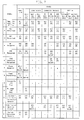
- Fig. 7 is a state diagram showing the events, states and actions of the link-level facility 70.
- the events of the link-level facility 70 are shown down the left side of the state diagram. The events are:
- a link-level facility can be in one of the following mutually exclusive states: Inactive (IN) Working (WK) Link Failure Transmit OLS (LF1) Transmit NOS (LF2) Connection Recovery UD-Transmission (CR1) UD-Reception (CR2) UDR-Reception (CR3) Offline Offline Transmit (OL1) Offline Received (OL2) Wait-for-Offline Sequence (OL3)
- LF1 Inactive
- WK Link Failure Transmit OLS
- LF1 Transmit NOS
- CR1 UD-Reception CR2
- UDR-Reception CR3 Offline Offline Transmit
- O1 Offline Received
- Wait-for-Offline Sequence OL3
- the state of the link-level facility 70 determines the actions to be taken when the specific events 1-13 occur. These events include information received from the link, information to be transmitted on the link, and link-level facility initiated operations.
- the link-level facility is in the inactive (IN) state when it is not in any of the other states.
- the link-level facility transmits idle characters on the link and can initiate monolog communication.
- the link-level facility can enter the inactive state from the working (WK) state or the connection-recovery UD-reception (CR2) or UDR-reception (CR3) state.
- the link-level facility changes from the inactive (IN) state to the working (WK) state.
- the link-level facility When a link-level facility has determined that it is temporarily unable to establish a two-way communication path, that is, link busy, the link-level facility changes from the inactive (IN) state to the working (WK) state.
- the link-level facility When the link-level facility has determined that it is to be taken offline and initiates the off line operation, the link-level facility changes from the inactive (IN) state to the offline-transmit (OLI) state.
- the link-level facility When the link-level facility has determined that connection recovery is to be performed and initiates the connection-recovery operation, the link-level facility changes from the inactive (IN) state to the connection-recovery UD-transmission (CR1) state.
- the link-level facility When the link-level facility has recognized the offline sequence, the link-level facility changes from the inactive (IN) state to the offline-received (OL2) state.
- the link-level facility When the link-level facility has recognized the not-operational sequence, the link-level facility changes from the inactive (IN) state to the link-failure transmit-OLS (LF1) state.
- the link-level facility When the link-level facility has recognized the unconditional-disconnect sequence, the link-level facility changes from the inactive (IN) state to the connection-recovery UD-reception (CR2) state.
- the link-level facility When the link-level facility has recognized the unconditional-disconnect-response sequence, the link-level facility changes from the inactive (IN) state to the connection-recovery UDR-reception (CR3) state.
- the link-level facility When the link-level facility has determined that a link-signal error persists for longer than the link-interval duration, the link-level facility changes from the inactive (IN) state to the link-failure transmit NOS (LF2) state.
- the link-level facility is in the working (WK) state when the link-level facility has performed either the process of frame reception or frame transmission and considers that monolog communication or dialog communication has occurred, or the link-level facility is link busy.
- Monolog communication is considered to exist when a two-way communication path is being established by the initial transmission or reception of an initiation frame.
- Dialog communication is considered to exist when a two-way communication path is established by the proper frame transmission or frame reception to a received or transmitted initiation frame, respectively.
- the link-level facility When the link-level facility considers the link to be in the working (WK) state, the link-level facility transmits idle characters on the link when it is not transmitting frames on the link.
- the link-level facility can enter the working (WK) state only from the inactive (IN) state.
- the link-level facility When the link-level facility does not have a monolog communication or a dialog communication condition and the link-level facility is not link busy, the link-level facility changes from the working (WK) state to the inactive (IN) state.
- the link-level facility When the link-level facility has determined that it is to be taken offline and initiates the offline operation, the link-level facility changes from the working (WK) state to the offline-transmit (OL1) state.
- the link-level facility When the link-level facility has determined that connection recovery is to be performed and initiates the connection-recovery operation, the link-level facility changes from the working (WK) state to the connection-recovery UD-transmission (CR1) state.
- the link-level facility When the link-level facility has recognized the offline sequence, the link-level facility changes from the working (WK) state to the offline-received (OL2) state.
- the link-level facility When the link-level facility has recognized the not-operational sequence, the link-level facility changes from the working (WK) state to the link-failure transmit-OLS (LF1) state.
- the link-level facility When the link-level facility has recognized the unconditional-disconnect sequence, the link-level facility changes from the working (WK) state to the connection-recovery UD-reception (CR2) state.
- WK working
- CR2 connection-recovery UD-reception
- the link-level facility When the link-level facility has recognized the unconditional-disconnect-response sequence, the link-level facility changes from the working (WK) state to the connection-recovery UDR-reception (CR3) state.
- the link-level facility When the link-level facility has determined that a link-signal error persists for longer than the link-interval duration, the link-level facility changes from the working (WK) state to the link-failure transmit-NOS (LF2) state.
- WK working
- LF2 link-failure transmit-NOS
- the link-level facility is in the link-failure (LF1 or LF2) state when the link-level facility recognizes an appropriate link-failure condition on the attached link such as a loss-of-signal or loss-of-sync condition. If the link-level facility is in the offline-transmit (OL1) state and is not interrogating the information received on the link (that is, the link-level facility is not prepared to leave the off line-transmit (OL1) state), then a link-failure condition is not recognized. There are two substates associated with the link-failure state: transmit OLS (LF1) and transmit NOS (LF2). The link-level facility can enter the link-failure state from any other state.
- LF1 link-failure
- LF2 link-failure
- a link-level facility leaves the link-failure state (LF1 or LF2) when (1) no link-failure condition is recognized on its attached link, or (2) a condition is recognized which causes the link-level facility to enter the offline state.
- the link-level facility is in the connection-recovery (CR1, CR2 or CR3) state when the connection-recovery procedure is being performed.
- Unconditional Disconnect (UD) sequences are sent during the connection-recovery procedure to cause the removal of a dynamic connection between the link of a link-level facility or dynamic switch port and any other link.
- Connection recovery uses the interlocked exchanges of the unconditional-disconnect (UD) and unconditional-disconnect-response (UDR) sequences.
- UD-transmission CR1
- UD-reception CR2
- UDR-reception CR3
- a link-level facility leaves the connection-recovery state when (1) the connection-recovery protocols are satisfied, or (2) a condition is recognized which causes the link-level facility to enter either the offline (OL1, OL2 or OL3) or the link-failure (LF1 or LF2) state.
- the link-level facility is in the offline state (OL1, OL2 or OL3) when the offline procedure is being performed. This typically occurs when the link-level facility or dynamic switch port is being powered on or off, or when the link address is being reset such as during initial microcode load (IML) of the system.
- the link-level facility enters the offline (OL1, OL2 or OL3) state when (1) the offline sequence is received and recognized from the link, or (2) the link-level facility has initiated an offline operation by causing the transmission of the offline sequence on the link.
- the link-level facility can enter the off line state from any other state.
- a link-level facility leaves the offline state when the offline protocols are satisfied.
- the link-level facility 70 When the link-level facility 70 is in one of its states, and an event occurs, the link-level facility 70 performs the action shown by the number in parentheses, and goes to the state indicated. For instance, when a (link failure is recognized) (event 11) and the link-level facility 70 is in the working (WK) state, the state changes to the link-failure transmit NOS (LF2) state and does action 6 (send NOS).
- LF2 link-failure transmit NOS
- send NOS The actions are defined as follows:
- Frame transmission by the link-level facility 70 is permitted on a link when the state machine 82 is in either the inactive (IN) or the working (WK) state.
- idle characters are discontinued only for the time necessary to transmit the frame. The transition from idle characters to frame transmission and the transition from frame transmission back to idle characters occur so that the appropriate transmission characters are always being transmitted on the link such that proper disparity is maintained.
- the link-level facility sending the frames separates the successive frames by continuous sequences of idle characters as shown in Fig. 5.
- Frame transmission begins when the first transmission character of the start-of-frame delimiter is sent and ends when the transmission character of the end-of-frame delimiter is sent. In the absence of errors, once transmission of a frame starts, the operation is synchronous and is not interrupted until the last transmission character of the end-of-frame delimiter is sent. After the end-of-frame delimiter is sent, idle characters are sent until the next frame or sequence is ready for transmission.
- the link-level facility 70 can receive a frame anytime after the receiver 72 has achieved synchronization. After synchronization is achieved, the character boundaries of the transmission being received are established, which permits the receiver 72 to search for an ordered set that represents a start-of-frame delimiter. Frame reception starts upon the recognition by the receiver 72 of a start-of-frame delimiter that is followed by any valid transmission character. Frame reception, when started, continues until delimiter ordered set is recognized, two consecutive idle characters are recognized, a defined continuous sequence is recognized, a quantity of transmission characters that exceeds the maximum which can be accepted for the conditions present is recognized, or a loss-of-signal or loss-of-sync condition is detected. When frame reception is ended by other than an end-of-frame delimiter ordered set, that which has been received is not considered to be a frame and is discarded.
Landscapes
- Engineering & Computer Science (AREA)
- Theoretical Computer Science (AREA)
- Physics & Mathematics (AREA)
- General Engineering & Computer Science (AREA)
- General Physics & Mathematics (AREA)
- Computer Networks & Wireless Communication (AREA)
- Signal Processing (AREA)
- Mathematical Physics (AREA)
- Computer Hardware Design (AREA)
- Communication Control (AREA)
- Computer And Data Communications (AREA)
Applications Claiming Priority (2)
| Application Number | Priority Date | Filing Date | Title |
|---|---|---|---|
| US07/575,923 US5151977A (en) | 1990-08-31 | 1990-08-31 | Managing a serial link in an input/output system which indicates link status by continuous sequences of characters between data frames |
| US575923 | 1990-08-31 |
Publications (3)
| Publication Number | Publication Date |
|---|---|
| EP0472833A2 true EP0472833A2 (de) | 1992-03-04 |
| EP0472833A3 EP0472833A3 (en) | 1992-06-03 |
| EP0472833B1 EP0472833B1 (de) | 1995-10-11 |
Family
ID=24302248
Family Applications (1)
| Application Number | Title | Priority Date | Filing Date |
|---|---|---|---|
| EP91109685A Expired - Lifetime EP0472833B1 (de) | 1990-08-31 | 1991-06-13 | Serielle Verbindung in einem Ein-/Ausgabesystem |
Country Status (5)
| Country | Link |
|---|---|
| US (1) | US5151977A (de) |
| EP (1) | EP0472833B1 (de) |
| JP (1) | JPH0658653B2 (de) |
| BR (1) | BR9103524A (de) |
| DE (1) | DE69113727T2 (de) |
Cited By (3)
| Publication number | Priority date | Publication date | Assignee | Title |
|---|---|---|---|---|
| EP0670551A1 (de) * | 1994-03-01 | 1995-09-06 | International Business Machines Corporation | Ferndoppelkopiesystem |
| EP0641139A3 (de) * | 1993-07-13 | 1997-12-29 | Hewlett-Packard Company | Kombinieren von Ton- und Fernsprech-Daten für einem Rechner |
| EP1863189B1 (de) * | 2001-05-30 | 2012-11-14 | LG Electronics Inc. | Netzwerksteuerungssystem für Haushaltsanwendungen |
Families Citing this family (10)
| Publication number | Priority date | Publication date | Assignee | Title |
|---|---|---|---|---|
| EP0453863A2 (de) * | 1990-04-27 | 1991-10-30 | National Semiconductor Corporation | Verfahren und Gerät zur Ausführung einer Mediumzugriffssteuerung/Wirtsystemschnittstelle |
| US5680151A (en) * | 1990-06-12 | 1997-10-21 | Radius Inc. | Method and apparatus for transmitting video, data over a computer bus using block transfers |
| JP2566728B2 (ja) * | 1992-10-30 | 1996-12-25 | インターナショナル・ビジネス・マシーンズ・コーポレイション | 論理径路スケジューリング装置及び実行方法 |
| US6064705A (en) | 1997-08-20 | 2000-05-16 | Sarnoff Corporation | Manchester encoding and decoding system |
| US6772108B1 (en) | 1999-09-22 | 2004-08-03 | Netcell Corp. | Raid controller system and method with ATA emulation host interface |
| US6501396B1 (en) | 2001-03-30 | 2002-12-31 | Xilinx, Inc. | Scalable physical coding sublayer (PCS) and 8B/10B encoder |
| US7137018B2 (en) * | 2002-12-31 | 2006-11-14 | Intel Corporation | Active state link power management |
| WO2004092942A2 (en) * | 2003-04-09 | 2004-10-28 | Netcell Corp. | Method and apparatus for synchronizing data from asynchronous disk drive data transfers |
| KR20060025135A (ko) * | 2003-04-21 | 2006-03-20 | 네트셀 코포레이션 | 재구성 가능한 데이터 경로를 갖는 디스크 어레이 제어기 |
| US20050036451A1 (en) * | 2003-08-12 | 2005-02-17 | Green Samuel I. | Portable instrument to test fibre channel nodes installed in an aircraft |
Family Cites Families (14)
| Publication number | Priority date | Publication date | Assignee | Title |
|---|---|---|---|---|
| US4200930A (en) * | 1977-05-23 | 1980-04-29 | Burroughs Corporation | Adapter cluster module for data communications subsystem |
| US4202035A (en) * | 1977-11-25 | 1980-05-06 | Mcdonnell Douglas Corporation | Modulo addressing apparatus for use in a microprocessor |
| US4292669A (en) * | 1978-02-28 | 1981-09-29 | Burroughs Corporation | Autonomous data communications subsystem |
| US4241398A (en) * | 1978-09-29 | 1980-12-23 | United Technologies Corporation | Computer network, line protocol system |
| US4425616A (en) * | 1979-11-06 | 1984-01-10 | Frederick Electronic Corporation | High-speed time share processor |
| DE3001638A1 (de) * | 1980-01-17 | 1981-07-23 | Siemens AG, 1000 Berlin und 8000 München | Passives bussystem fuer dezentral strukturierte mehrrechneranordnungen, insbesondere multimikrocomputer-anordnungen |
| US4468734A (en) * | 1982-03-26 | 1984-08-28 | International Business Machines Corporation | Method of purging erroneous signals from closed ring data communication networks capable of repeatedly circulating such signals |
| US4613979A (en) * | 1984-05-03 | 1986-09-23 | Zenith Electronics Corporation | Continuous, automatic reset of synchronous data receiver upon detection of loss of sync |
| US4675864A (en) * | 1985-06-04 | 1987-06-23 | Hewlett-Packard Company | Serial bus system |
| US4647925A (en) * | 1985-06-26 | 1987-03-03 | Burroughs Corporation | Circuit employing intercoupled state machines for transmitting and receiving multiformatted sequences of voice and data characters |
| US4972368A (en) * | 1988-03-04 | 1990-11-20 | Stallion Technologies, Pty. Ltd. | Intelligent serial I/O subsystem |
| US4939735A (en) * | 1988-07-21 | 1990-07-03 | International Business Machines Corporation | Information handling system having serial channel to control unit link |
| US5003558A (en) * | 1989-10-30 | 1991-03-26 | International Business Machines Corporation | Data synchronizing buffers for data processing channels |
| US5048062A (en) * | 1989-10-30 | 1991-09-10 | International Business Machines Corp. | Transmitting commands over a serial link |
-
1990
- 1990-08-31 US US07/575,923 patent/US5151977A/en not_active Expired - Lifetime
-
1991
- 1991-06-13 DE DE69113727T patent/DE69113727T2/de not_active Expired - Lifetime
- 1991-06-13 EP EP91109685A patent/EP0472833B1/de not_active Expired - Lifetime
- 1991-06-18 JP JP3171945A patent/JPH0658653B2/ja not_active Expired - Fee Related
- 1991-08-16 BR BR919103524A patent/BR9103524A/pt not_active IP Right Cessation
Cited By (4)
| Publication number | Priority date | Publication date | Assignee | Title |
|---|---|---|---|---|
| EP0641139A3 (de) * | 1993-07-13 | 1997-12-29 | Hewlett-Packard Company | Kombinieren von Ton- und Fernsprech-Daten für einem Rechner |
| EP1152343A1 (de) * | 1993-07-13 | 2001-11-07 | Hewlett-Packard Company, A Delaware Corporation | Vorrichtung und Verfahren zur Kommunikation zwischen einem Rechner und einem periphären Gerät |
| EP0670551A1 (de) * | 1994-03-01 | 1995-09-06 | International Business Machines Corporation | Ferndoppelkopiesystem |
| EP1863189B1 (de) * | 2001-05-30 | 2012-11-14 | LG Electronics Inc. | Netzwerksteuerungssystem für Haushaltsanwendungen |
Also Published As
| Publication number | Publication date |
|---|---|
| JPH04238557A (ja) | 1992-08-26 |
| JPH0658653B2 (ja) | 1994-08-03 |
| DE69113727T2 (de) | 1996-05-30 |
| BR9103524A (pt) | 1992-05-12 |
| EP0472833B1 (de) | 1995-10-11 |
| DE69113727D1 (de) | 1995-11-16 |
| EP0472833A3 (en) | 1992-06-03 |
| US5151977A (en) | 1992-09-29 |
Similar Documents
| Publication | Publication Date | Title |
|---|---|---|
| EP0425777B1 (de) | Vermittlungsverfahren und -protokoll zur Herstellung von dynamischen Verbindungen | |
| US5420988A (en) | Establishing logical paths through a switch between channels and control units in a computer I/O system | |
| US4929939A (en) | High-speed switching system with flexible protocol capability | |
| EP0020636B1 (de) | Datenübertragungssystem mit autonomem endgerät | |
| EP0472833B1 (de) | Serielle Verbindung in einem Ein-/Ausgabesystem | |
| EP0274709B1 (de) | Protokoll für Paketvermittlungsnetz | |
| EP0244117B1 (de) | Verfahren zur Duplex-Datenübertragung unter Verwendung eines Sende- und Warteprotokolls | |
| US4368512A (en) | Advanced data link controller having a plurality of multi-bit status registers | |
| AU600128B2 (en) | Virtual computer session management link | |
| US4567590A (en) | Message stripping protocol for a ring communication network | |
| EP0529220B1 (de) | Verfahren zur Erfassung des Identifizierers eines Knotens in einem Ein-/Ausgabesystem | |
| EP0472835B1 (de) | Melden und Verifizieren von Zustandswechseln in einem Datenverarbeitungsein- / -ausgabesystem | |
| US5276813A (en) | Acquiring addresses in an input/output system | |
| EP0371593B1 (de) | Verfahren zur Initialisierung oder Synchronisierung einer Übertragungsleitung | |
| US5206860A (en) | Recovery from a possible switching error in a computer i/o system | |
| US5450073A (en) | Controlling power sequencing of a control unit in an input/output system | |
| JPH09130408A (ja) | ネットワークインタフェース装置 | |
| JPH0191556A (ja) | 不定形通信網のノ−ド装置 | |
| US5027346A (en) | Node apparatus for parallel communication | |
| JP2510077B2 (ja) | 直列リンクとドライバおよびレシ―バの速度とをペ―シングするための空語制御方法 | |
| JP2616246B2 (ja) | デュアル運転二重化装置における系間データのデュアル処理方法およびデュアル運転二重化装置 | |
| JPH0354909B2 (de) | ||
| JPS61292444A (ja) | 通信制御方式 | |
| JPH05268243A (ja) | Atm伝送におけるセル廃棄防止方式 | |
| JPH1127338A (ja) | 通信装置および通信方法 |
Legal Events
| Date | Code | Title | Description |
|---|---|---|---|
| PUAI | Public reference made under article 153(3) epc to a published international application that has entered the european phase |
Free format text: ORIGINAL CODE: 0009012 |
|
| AK | Designated contracting states |
Kind code of ref document: A2 Designated state(s): DE FR GB |
|
| PUAL | Search report despatched |
Free format text: ORIGINAL CODE: 0009013 |
|
| AK | Designated contracting states |
Kind code of ref document: A3 Designated state(s): DE FR GB |
|
| 17P | Request for examination filed |
Effective date: 19920619 |
|
| 17Q | First examination report despatched |
Effective date: 19940425 |
|
| GRAA | (expected) grant |
Free format text: ORIGINAL CODE: 0009210 |
|
| AK | Designated contracting states |
Kind code of ref document: B1 Designated state(s): DE FR GB |
|
| REF | Corresponds to: |
Ref document number: 69113727 Country of ref document: DE Date of ref document: 19951116 |
|
| ET | Fr: translation filed | ||
| PLBE | No opposition filed within time limit |
Free format text: ORIGINAL CODE: 0009261 |
|
| STAA | Information on the status of an ep patent application or granted ep patent |
Free format text: STATUS: NO OPPOSITION FILED WITHIN TIME LIMIT |
|
| 26N | No opposition filed | ||
| REG | Reference to a national code |
Ref country code: GB Ref legal event code: IF02 |
|
| REG | Reference to a national code |
Ref country code: GB Ref legal event code: 746 Effective date: 20090519 |
|
| PGFP | Annual fee paid to national office [announced via postgrant information from national office to epo] |
Ref country code: FR Payment date: 20100701 Year of fee payment: 20 |
|
| PGFP | Annual fee paid to national office [announced via postgrant information from national office to epo] |
Ref country code: GB Payment date: 20100625 Year of fee payment: 20 Ref country code: DE Payment date: 20100625 Year of fee payment: 20 |
|
| REG | Reference to a national code |
Ref country code: DE Ref legal event code: R071 Ref document number: 69113727 Country of ref document: DE |
|
| REG | Reference to a national code |
Ref country code: DE Ref legal event code: R071 Ref document number: 69113727 Country of ref document: DE |
|
| REG | Reference to a national code |
Ref country code: GB Ref legal event code: PE20 Expiry date: 20110612 |
|
| PG25 | Lapsed in a contracting state [announced via postgrant information from national office to epo] |
Ref country code: GB Free format text: LAPSE BECAUSE OF EXPIRATION OF PROTECTION Effective date: 20110612 |
|
| PG25 | Lapsed in a contracting state [announced via postgrant information from national office to epo] |
Ref country code: DE Free format text: LAPSE BECAUSE OF EXPIRATION OF PROTECTION Effective date: 20110614 |