EP0473381A2 - Appareillage et méthode de fixation d'un ensemble de câble de retenue et de cordon blindé à un combiné et un boitier téléphonique - Google Patents
Appareillage et méthode de fixation d'un ensemble de câble de retenue et de cordon blindé à un combiné et un boitier téléphonique Download PDFInfo
- Publication number
- EP0473381A2 EP0473381A2 EP91307800A EP91307800A EP0473381A2 EP 0473381 A2 EP0473381 A2 EP 0473381A2 EP 91307800 A EP91307800 A EP 91307800A EP 91307800 A EP91307800 A EP 91307800A EP 0473381 A2 EP0473381 A2 EP 0473381A2
- Authority
- EP
- European Patent Office
- Prior art keywords
- handset
- housing
- armoured
- cord
- restraint cable
- Prior art date
- Legal status (The legal status is an assumption and is not a legal conclusion. Google has not performed a legal analysis and makes no representation as to the accuracy of the status listed.)
- Withdrawn
Links
Images



Classifications
-
- H—ELECTRICITY
- H04—ELECTRIC COMMUNICATION TECHNIQUE
- H04M—TELEPHONIC COMMUNICATION
- H04M1/00—Substation equipment, e.g. for use by subscribers
- H04M1/02—Constructional features of telephone sets
- H04M1/15—Protecting or guiding telephone cords
Definitions
- the present invention is directed to an apparatus and a method for anchoring the two ends of an armoured telephone cord and restraint cable assembly to both the telephone housing and the associated telephone handset.
- the typical telephone armoured cord and restraint cable assembly comprises a central restraint cable having a tensile strength on the order of 1,000 pound (454kg) test or greater, and which is surrounded by electrical wires that extend between the housing and the handset for carrying electronic signals between them.
- the restraint cable and the telephone wires are surrounded with an armoured sheath fabricated of a helically- wound metal strip, in order to protect the wires and facilitate the flexure of the restraint cable-wire-armoured sheath combination.
- the armoured cord and restraint cable assembly extends from inside the telephone housing and to the other end into the handset.
- the restraint cable then extends longitudinally along the hollow handle portion of the handset, with the electrical wires being distributed to the respective transmitter and receiver ends of the handset (present industry practice uses a handset in which the armoured cord and restraint cable assembly extends through the handset at the transmitter end).
- U.S. Patent US-A-4,518,830 to Drexler et al discusses in detail prior art techniques used in the public telephone industry for anchoring both ends of an armoured cord and restraint cable assembly.
- Drexler et al employ fixed moulded upstanding walls inside the handgrip portion of the handset with a restricted opening adjacent the receiver end for holding a stop attached at the extremity of the restraint cable.
- a second anchoring technique employs a removable wedge-shaped anchor which fits into the restriction at the interface between the hollow handle and the receiver end of the telephone (see Figures 9 and 11 of the Drexler et al patent).
- Drexler et al disclose an elbow which extends the stop for the restraint cable inside the telephone housing (see Figures 4 to 7).
- the present invention employs a technique which anchors the cable stop attached to the housing end of the armoured cord and restraint cable assembly outside of the housing and in a direction extending generally parallel with the side surface of the housing into which telephone wires are extended, thus greatly simplifying the attachment of the armoured cord to the housing, without the need to feed the armoured cord inside the housing.
- the elbow is provided with a pair of prongs and a shaped opening for receiving a cable stop on the end of the restraint cable inside the cord and operating to hold the stop in a generally flat, parallel relationship with respect to the housing side surface.
- the elbow is conventionally attached to the side surface of the telephone housing via a C-ring or other conventional locking feature.
- the armoured telephone cord to the telephone housing is used in combination with a telephone handset in which a removable restraint cable anchor is positioned in the hollow hand-grip portion of the handset, with the restraint cable fixed to that anchor.
- the inner sidewalls of the hollow hand- grip portion are provided with means for restraining the anchor against movement toward the transmitter end in response to an external force along the restraint cable, so that any of the longitudinal forces caused by heavy pulling (either accidental or intentional) upon the restraint cable are transmitted as shear forces longitudinally along the sidewalls of the hand-grip portion.
- the restraining means comprises one or more ledges along the periphery of the internal side surfaces of the hand-grip portion.
- one or more of those walls may be thickened including any ledge portion which restrains movement of the removable anchor.
- the removable anchor is provided with an appropriate opening for receiving a restraint cable stop of greater diameter, and may include a slot to facilitate passage of electrical wires to the receiver end of the handset.
- the ledge which forms the restraining means may either engage the removable anchor along the bottom surface, or alternatively be shaped in conformity with a ledge or protrusion along a side surface of the removable anchor.
- a typical public telephone of the type used in the U.S.A. includes a telephone housing 12 having a surface 14 to which a dial 16 and handset cradle 18 are attached.
- the public telephone 10 includes a coin opening 20, a coin box 22 and a coin return 24.
- the public telephone 10 further includes a handset 26 which is electronically and mechanically connected to the housing 12 via an armoured cord and restraint cable assembly 28.
- the armoured cord and restraint cable assembly 28 includes an outer armoured sheath 40, multiple electrical wires 42 and a restraint cable 41.
- a cable stop 43 (see Figure 3) of substantially greater diameter than the restraint cable 41 is attached to the extremity of the restraint cable in the handset 26.
- the handset 26 includes a receiver end 30, a transmitter end 32 and a hand-grip portion 34 (the hand-grip portion is sometimes referred to as the "yoke").
- the hand-grip portion 34 is defined by four peripheral sidewalls 35, 36, 37 and 38 which are typically in a rectangular configuration and with corresponding internal sidewalls defining a hollow area through which the electronic wires 42 and the restraint cable 41 extend.
- the handset 26 is usually fabricated from a moulded plastic, with the covers for the receiver 30 and transmitter 32 being threaded on to the respective ends, as shown by threads 31 in Figure 2.
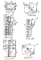
- a removable restraint cable anchor 44 is fitted into the hand-grip portion 34 of the handset 26 and between the receiver and transmitter ends 30, 32. It is preferred that the removable anchor 44 be positioned along the hand-grip portion 34 away from the thin gauged portion 33 of the sidewall 35 which curves into the receiver end 30.
- One or more of the peripheral sidewalls 35 to 38 of the hand-grip portion 34 are provided with means for restraining the anchor44 against movement through the hand-grip portion 34 toward the transmitter end 32. In the arrangement of Figures 2 to 5, this is achieved using a single ledge 39 along the inside peripheral sidewall 35. It is also noted that further strengthening can be achieved by the thickening of that sidewall 35.
- the positioning of the removable anchor 44 along the hand-grip portion 34 and the use of the ledge 39 causes pulling forces exerted upon the armoured cord and restraint cable assembly 28, including the restraint cable 41, to be transmitted as a shear force downwardly along the inside peripheral sidewall 35, as opposed to being transmitted through the thinned portion 33 of the sidewall 35 that curves into the receiver end 30.
- the peripheral sidewall arrangement shown in Figure 2 permits extremely high longitudinal forces to be applied to the restraint cable 41 without breaking the plastic materials that are normally used in the fabrication of the handset 26.
- the thickening of the inside peripheral sidewall 35 at the ledge 39 contributes to an even greater strengthening against such longitudinal pulling along the restraint cable 41.
- one form of the restraint anchor 44 includes a first slot 46 along the rear for receiving the electrical wires 42 that pass along the hand-grip portion 34 to the receiver end 30 (also note Figure 2).
- a second slot 48 extends centrally into the removable anchor 44 and into a central opening 50 which is dimensioned to receive the cable stop 43 attached to the end of the restraint cable 41.
- the restraint cable may be easily slipped through the slot48 and extended downwardly toward the transmitter end so that the cable stop 43 engages into the opening 50.
- a second form of a removable anchor 54 is shown in Figures 6 and 7.
- the removable anchor 54 includes a slot 56 for receiving the electrical wires 42, and a longitudinal hole 58 communicating with an opening 60, the opening 60 dimensioned to receive the cable stop 43.
- the anchor 54 is thus essentially identical to the anchor 44 of Figures 3 to 5, except that a portion of the slot 48 is omitted.
- FIG. 8 Another form of a removable anchor 64 is shown in Figures 8 and 9.
- the anchor 64 has a protrusion or ledge 65 along the front surface 67 of the anchor 64.
- the peripheral sidewall 35A of the hand-grip portion 34 in the form of Figure 8 includes a corresponding ledge or protrusion 63 which mates with the protrusion or ledge 65 along the front surface 67 of the anchor 64.
- the anchor 64 also includes a slot 66 for receiving the electrical wires 42 passing along to the receiver end 30 of the handset, and a slot 68 and opening 70 for receiving the restraint cable 42 and the cable stop 43.
- the ledge 39 is moulded along the inner sidewall 35 of the handgrip portion 34.
- Other suitable ledge arrangements are shown in Figures 10 to 12.
- a pair of ledges 72 may be placed on the inside of the opposing of inner and outer sidewalls 35, 37.
- opposing ledges 74 are moulded along the sidewalls 36, 38.
- corner ledges 76 are moulded between adjacent sidewalls 35 to 38.
- the ledges shown in Figures 10 to 12 are positioned along an intermediate portion of the internal passageway of the hand-grip portion 34 defined by the sidewalls 35 to 38, in order to engage the particular form of the removable anchor 44, 54 or 64.
- the anchor 80 is supported by a ledge 82 somewhat below the curvature 84 of the receiver end of the handset.
- the anchor 80 includes a first slot 86 for receiving the wires 42, and a second slot 88 dimensioned to receive the restraint cable 41, so as to be engaged in an opening 90.
- a similar form of the invention is shown in Figures 16 and 17, and is identified by the reference numeral 92. This arrangement includes a first slot 94 for receiving the wires, a second slot 96 for receiving the restraint cable, and an opening 98 for receiving the restraint cable stop.
- any ledge, protrusion or thickened wall portion along any sidewall (or between sidewalls) of the hand-grip portion of the telephone may likewise have a mating relationship with any protrusion or ledge along any corresponding wall of the removable anchor.
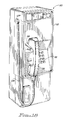
- a conventional public telephone 110 of the type used in Europe has a housing 112 and a side surface 114 to which is attached an elbow 127.
- the telephone 110 also includes a key pad 116, a handset cradle 118 and an armoured telephone cord and restraint cable assembly 128 essentially identical to the assembly 28 shown and described with reference to Figures 1 to 3. It will of course be observed that the end of the telephone cord and restraint cable assembly 128 in Figure 18 differs significantly from the arrangement of Figure 1; in the arrangement of Figure 18, the assembly 128 at the housing passes into the elbow 127 along the sidewall 113 of the housing 112, whereas in the arrangement of Figure 1, the assembly 28 extends into a front plate 14 of the housing 12.
- the elbow 127 is fabricated from a generally flat cylindrical body portion 129 having a pair of prongs 132, 134 which extend into the sidewall 114 of the telephone housing 112.
- the prongs include a circular groove 136 into which is inserted a C-ring 138 for locking the prongs inside the sidewall 114, much in the manner of the C-ring 175 in Figure 7 of the above described Drexler et al patent.
- the body 129 of the elbow 127 includes a lateral opening 139 dimensioned to receive the armoured sheath portion of the assembly 128, with the restraint cable 141 extending across the central portion of the body to a cable stop 143.
- the body 129 of the elbow 127 includes a pair of locking tabs 142 which extend into the space between the cable stop 143 and the end of the armoured sheath of the assembly 128, forming a locking opening 146 for the cable stop 143.
- the electrical wires 148 then extend out of the assembly 128, at a right angle through the body 129 and then into the housing 112 of the telephone 110 shown in Figure 18.
- the elbow 127 may be easily retrofitted onto an existing public telephone of the type shown in Figure 18, by simply removing the existing elbow and then retrofitting the elbow 127 with an armoured telephone cord and restraint cable assembly 128 in place, with the elbow 127 holding the armoured cord 128 and the cable stop 143 in place.
- the present invention provides a particularly simple, but effective method of adapting telephone housings of the type described, i.e. comprising an elbow joint for entry of the cord into the housing, for use with telephones employing an armoured cord connecting the handset to the telephone housing, and more particularly for anchoring the cord to the housing.
Landscapes
- Engineering & Computer Science (AREA)
- Signal Processing (AREA)
- Telephone Set Structure (AREA)
Applications Claiming Priority (2)
| Application Number | Priority Date | Filing Date | Title |
|---|---|---|---|
| US572152 | 1984-01-19 | ||
| US07/572,152 US5136635A (en) | 1990-08-23 | 1990-08-23 | Apparatus and method for securing an armored cord and restraint cable assembly to a telephone handset and housing |
Publications (2)
| Publication Number | Publication Date |
|---|---|
| EP0473381A2 true EP0473381A2 (fr) | 1992-03-04 |
| EP0473381A3 EP0473381A3 (en) | 1992-06-03 |
Family
ID=24286568
Family Applications (1)
| Application Number | Title | Priority Date | Filing Date |
|---|---|---|---|
| EP19910307800 Withdrawn EP0473381A3 (en) | 1990-08-23 | 1991-08-23 | Apparatus and method for securing an armoured cord and restraint cable assembly to a telephone handset and housing |
Country Status (2)
| Country | Link |
|---|---|
| US (1) | US5136635A (fr) |
| EP (1) | EP0473381A3 (fr) |
Cited By (2)
| Publication number | Priority date | Publication date | Assignee | Title |
|---|---|---|---|---|
| WO1995020856A1 (fr) * | 1994-01-31 | 1995-08-03 | Hosiden Besson Limited | Connecteurs de cables pour combines telephoniques |
| WO2004004290A1 (fr) * | 2002-06-29 | 2004-01-08 | Ritto Gmbh & Co. Kg | Telephone mural a combine suspendu |
Families Citing this family (2)
| Publication number | Priority date | Publication date | Assignee | Title |
|---|---|---|---|---|
| US5577119A (en) * | 1995-05-08 | 1996-11-19 | I.D. Tel Corp. | Tension resisting bracket for telephone handsets |
| US8537012B2 (en) * | 2009-09-23 | 2013-09-17 | Checkpoint Systems, Inc. | Display assembly with cable stop |
Family Cites Families (6)
| Publication number | Priority date | Publication date | Assignee | Title |
|---|---|---|---|---|
| JPS5239848Y2 (fr) * | 1972-06-02 | 1977-09-09 | ||
| US4518830A (en) * | 1982-06-25 | 1985-05-21 | At&T Bell Laboratories | Armored telephone cord with a longitudinal strength member |
| US4837815A (en) * | 1986-06-26 | 1989-06-06 | Nynex Corporation | Armored cord handset |
| US4845774A (en) * | 1986-10-06 | 1989-07-04 | Raymond Arzounian | Apparatus for anchoring a telephone handset to a telephone housing |
| JPH01258535A (ja) * | 1988-04-08 | 1989-10-16 | Toshiba Corp | 電話機 |
| US4974258A (en) * | 1989-07-21 | 1990-11-27 | Raytel, Inc. | Vandal-proof handset for a pay telephone |
-
1990
- 1990-08-23 US US07/572,152 patent/US5136635A/en not_active Expired - Lifetime
-
1991
- 1991-08-23 EP EP19910307800 patent/EP0473381A3/en not_active Withdrawn
Cited By (4)
| Publication number | Priority date | Publication date | Assignee | Title |
|---|---|---|---|---|
| WO1995020856A1 (fr) * | 1994-01-31 | 1995-08-03 | Hosiden Besson Limited | Connecteurs de cables pour combines telephoniques |
| GB2293055A (en) * | 1994-01-31 | 1996-03-13 | Hosiden Besson Ltd | Cable connectors for telephone handsets |
| GB2293055B (en) * | 1994-01-31 | 1997-12-10 | Hosiden Besson Ltd | Cable connectors for telephone handsets |
| WO2004004290A1 (fr) * | 2002-06-29 | 2004-01-08 | Ritto Gmbh & Co. Kg | Telephone mural a combine suspendu |
Also Published As
| Publication number | Publication date |
|---|---|
| US5136635A (en) | 1992-08-04 |
| EP0473381A3 (en) | 1992-06-03 |
Similar Documents
| Publication | Publication Date | Title |
|---|---|---|
| US6396993B1 (en) | Optical fiber breakaway apparatus and method | |
| CA1195743A (fr) | Cordon telephonique arme avec element de renforcement longitudinal | |
| KR100245143B1 (ko) | 안티-스낵의 복식 커넥터 | |
| US6266469B1 (en) | Fiber optic cable pulling device | |
| US20020003940A1 (en) | Optical fiber holder | |
| EP1373954B1 (fr) | Dispositif terminal de cables | |
| KR880002026A (ko) | 광섬유 케이블용 커넥터 | |
| AU2002242836A1 (en) | Cable termination device | |
| GB2193902A (en) | Climbing aids | |
| US20050254768A1 (en) | Drop wire clamp | |
| US7234669B2 (en) | Clamp | |
| EP0473381A2 (fr) | Appareillage et méthode de fixation d'un ensemble de câble de retenue et de cordon blindé à un combiné et un boitier téléphonique | |
| MY124484A (en) | Ribbon cable connector assembly | |
| CA2327687C (fr) | Boite de jonction adaptable au diametre des conduits | |
| US6231369B1 (en) | Bolted type connector | |
| KR910000844B1 (ko) | 외장코드 송수화기 | |
| JPH0440906B2 (fr) | ||
| EP1556925B1 (fr) | Ensemble raccord de cable et systeme associe | |
| EP0709925B1 (fr) | Receptacle pour assemblage de connecteur | |
| WO2000049441A1 (fr) | Pince a ressort | |
| JPH10133030A (ja) | 光ケーブル接続用収納ケース | |
| EP0631345A1 (fr) | Dispositif d'atténuation de câble et méthode d'utilisation | |
| JP3851573B2 (ja) | 光ケーブル通信線の成端キャビネット | |
| WO2011073259A1 (fr) | Connecteur de câble | |
| JPH1010337A (ja) | 光ケーブル接続用収納ケース |
Legal Events
| Date | Code | Title | Description |
|---|---|---|---|
| PUAI | Public reference made under article 153(3) epc to a published international application that has entered the european phase |
Free format text: ORIGINAL CODE: 0009012 |
|
| AK | Designated contracting states |
Kind code of ref document: A2 Designated state(s): CH DE FR GB LI |
|
| PUAL | Search report despatched |
Free format text: ORIGINAL CODE: 0009013 |
|
| AK | Designated contracting states |
Kind code of ref document: A3 Designated state(s): CH DE FR GB LI |
|
| STAA | Information on the status of an ep patent application or granted ep patent |
Free format text: STATUS: THE APPLICATION IS DEEMED TO BE WITHDRAWN |
|
| 18D | Application deemed to be withdrawn |
Effective date: 19930215 |