EP0475447A2 - Magnetisch aufzeichenbaren photographischen Film, Aufzeichnungsverfahren und Vorrichtung dazu, sowie ein Kamera-Labor System - Google Patents
Magnetisch aufzeichenbaren photographischen Film, Aufzeichnungsverfahren und Vorrichtung dazu, sowie ein Kamera-Labor System Download PDFInfo
- Publication number
- EP0475447A2 EP0475447A2 EP91115592A EP91115592A EP0475447A2 EP 0475447 A2 EP0475447 A2 EP 0475447A2 EP 91115592 A EP91115592 A EP 91115592A EP 91115592 A EP91115592 A EP 91115592A EP 0475447 A2 EP0475447 A2 EP 0475447A2
- Authority
- EP
- European Patent Office
- Prior art keywords
- film
- recording
- magnetic
- information
- camera
- Prior art date
- Legal status (The legal status is an assumption and is not a legal conclusion. Google has not performed a legal analysis and makes no representation as to the accuracy of the status listed.)
- Ceased
Links
Images


Classifications
-
- G—PHYSICS
- G03—PHOTOGRAPHY; CINEMATOGRAPHY; ANALOGOUS TECHNIQUES USING WAVES OTHER THAN OPTICAL WAVES; ELECTROGRAPHY; HOLOGRAPHY
- G03B—APPARATUS OR ARRANGEMENTS FOR TAKING PHOTOGRAPHS OR FOR PROJECTING OR VIEWING THEM; APPARATUS OR ARRANGEMENTS EMPLOYING ANALOGOUS TECHNIQUES USING WAVES OTHER THAN OPTICAL WAVES; ACCESSORIES THEREFOR
- G03B27/00—Photographic printing apparatus
- G03B27/32—Projection printing apparatus, e.g. enlarger, copying camera
- G03B27/46—Projection printing apparatus, e.g. enlarger, copying camera for automatic sequential copying of different originals, e.g. enlargers, roll film printers
- G03B27/462—Projection printing apparatus, e.g. enlarger, copying camera for automatic sequential copying of different originals, e.g. enlargers, roll film printers in enlargers, e.g. roll film printers
-
- G—PHYSICS
- G03—PHOTOGRAPHY; CINEMATOGRAPHY; ANALOGOUS TECHNIQUES USING WAVES OTHER THAN OPTICAL WAVES; ELECTROGRAPHY; HOLOGRAPHY
- G03B—APPARATUS OR ARRANGEMENTS FOR TAKING PHOTOGRAPHS OR FOR PROJECTING OR VIEWING THEM; APPARATUS OR ARRANGEMENTS EMPLOYING ANALOGOUS TECHNIQUES USING WAVES OTHER THAN OPTICAL WAVES; ACCESSORIES THEREFOR
- G03B17/00—Details of cameras or camera bodies; Accessories therefor
- G03B17/24—Details of cameras or camera bodies; Accessories therefor with means for separately producing marks on the film, e.g. title, time of exposure
-
- G—PHYSICS
- G03—PHOTOGRAPHY; CINEMATOGRAPHY; ANALOGOUS TECHNIQUES USING WAVES OTHER THAN OPTICAL WAVES; ELECTROGRAPHY; HOLOGRAPHY
- G03D—APPARATUS FOR PROCESSING EXPOSED PHOTOGRAPHIC MATERIALS; ACCESSORIES THEREFOR
- G03D15/00—Apparatus for treating processed material
- G03D15/001—Counting; Classifying; Marking
- G03D15/003—Marking, e.g. for re-printing
-
- G—PHYSICS
- G03—PHOTOGRAPHY; CINEMATOGRAPHY; ANALOGOUS TECHNIQUES USING WAVES OTHER THAN OPTICAL WAVES; ELECTROGRAPHY; HOLOGRAPHY
- G03B—APPARATUS OR ARRANGEMENTS FOR TAKING PHOTOGRAPHS OR FOR PROJECTING OR VIEWING THEM; APPARATUS OR ARRANGEMENTS EMPLOYING ANALOGOUS TECHNIQUES USING WAVES OTHER THAN OPTICAL WAVES; ACCESSORIES THEREFOR
- G03B2206/00—Systems for exchange of information between different pieces of apparatus, e.g. for exchanging trimming information, for photo finishing
- G03B2206/004—Systems for exchange of information between different pieces of apparatus, e.g. for exchanging trimming information, for photo finishing using markings on the photographic material, e.g. to indicate pseudo-panoramic exposure
-
- G—PHYSICS
- G03—PHOTOGRAPHY; CINEMATOGRAPHY; ANALOGOUS TECHNIQUES USING WAVES OTHER THAN OPTICAL WAVES; ELECTROGRAPHY; HOLOGRAPHY
- G03B—APPARATUS OR ARRANGEMENTS FOR TAKING PHOTOGRAPHS OR FOR PROJECTING OR VIEWING THEM; APPARATUS OR ARRANGEMENTS EMPLOYING ANALOGOUS TECHNIQUES USING WAVES OTHER THAN OPTICAL WAVES; ACCESSORIES THEREFOR
- G03B2217/00—Details of cameras or camera bodies; Accessories therefor
- G03B2217/24—Details of cameras or camera bodies; Accessories therefor with means for separately producing marks on the film
- G03B2217/242—Details of the marking device
- G03B2217/244—Magnetic devices
-
- G—PHYSICS
- G03—PHOTOGRAPHY; CINEMATOGRAPHY; ANALOGOUS TECHNIQUES USING WAVES OTHER THAN OPTICAL WAVES; ELECTROGRAPHY; HOLOGRAPHY
- G03B—APPARATUS OR ARRANGEMENTS FOR TAKING PHOTOGRAPHS OR FOR PROJECTING OR VIEWING THEM; APPARATUS OR ARRANGEMENTS EMPLOYING ANALOGOUS TECHNIQUES USING WAVES OTHER THAN OPTICAL WAVES; ACCESSORIES THEREFOR
- G03B2217/00—Details of cameras or camera bodies; Accessories therefor
- G03B2217/24—Details of cameras or camera bodies; Accessories therefor with means for separately producing marks on the film
- G03B2217/246—Details of the markings
Definitions
- This invention relates to a magnetically recordable photographic film, a recording method and a recording system employing the photographic film, and a camera laboratory system employing the photographic film.
- the invention encompasses the following first to fifth Aspects.
- This invention relates, in its first Aspect, to disposition of a perforation relative to an information recording region of a photographic film having a transparent magnetic recording layer.
- This invention relates, in its second Aspect, to a photographic film having a transparent magnetic recording layer, a recording method and a recording system for recording on said film and, above all, to a relation between the photographic film and the perforation in the photographic film and to a recording system especially for camera information.
- This invention relates, in its third Aspect, to a recording method for a photographic film provided with a transparent magnetic recording layer, and a photographic film used in the recording method and more particularly to recording of film information.
- This invention relates, in its fourth Aspect, to camera and laboratory system and, more particularly, to a camera system having a magnetic device for magnetic recording and, above all, to clock signals, the relation between the clock signals and data signals, and to the relation between the pulse frequency and the film transport speed.
- This invention relates, in its fifth Aspect, to a camera system and, more particularly, to a camera system having a magnetic device for magnetic recording.
- a photographic film having a transparent magnetic recording layer has been disclosed in international patent applications having international filing numbers PCT/US 89/04367 and PCT/US 89/04362 and laid open to public inspection internationally (now WO 90/04214 and WO 90/04253). These international patent applications disclose disposition of information recording regions on a photographic film, as shown herein in Fig. 23. This figure shows, in a front view, a conventional photographic film 100 disclosed in the above referenced international applications.
- a perforation 125 is formed in a region A defined by a long side I of a rectangular photosensitive image area defined by a double-dotted chain line, i.e., frame, and extensions of two short sides m and n of the frame adjacent to the long side I, that is, in a laterally peripheral region of the framed Meanwhile CO to C3 and F00 to F29 represent magnetic recording tracks.
- a photographic film having a transparent recording layer is disclosed in international applications filed under international application numbers PCT/US 89/04367 and PCT/US 89/04362 and laid open to public inspection internationally (now WO 90/04214 and WO 90/04253).
- a pattern of disposition of information recording regions on a photographic film is disclosed.
- a conventional photographic film 100 which is disclosed in the above identified international applications, and which includes magnetic recording tracks CO to C3 and F00 to F29, a photosensitive image area (i.e., frame), defined by a double-dotted chain line, and a perforation 125. It is stated in the specification of each of the international applications that information may be recorded on the magnetically recordable tracks CO to C3 by a camera capable of effecting magnetic recording.
- Such camera system is disclosed in an international publication WO 90/04253.
- recording tracks each specifically dedicated to the camera users, film dealers and the photofinishers, respectively are provided in separate portions on the film.
- clock signals and data signals are formed as unitary pulse trains in the form of three-bit encoded data (so called "Tri-bit code").
- Fig. 24 The waveform of the three-bit encoded data disclosed in the above international publications is shown herein in Fig. 24, in which rising transition pulse flanks P1A and P2A in each of the rectangular pulses correspond to clock signals prescribing a period t of signals to be recorded.
- the data signal is a binary signal having a logical level of 0.
- the pulse width td 2t/3
- the data signal is a binary signal having a logical level of 1.
- the waveform of reproduced signals which are the magnetic recordings made by the signals shown in Fig.24 and reproduced by a magnetic head, is shown in Fig.25.
- positive peak pulses Q1A, Q2A are produced at time points corresponding to the clock signals, while a negative peak pulse Q1 B is produced at a time point corresponding to the data signal.
- the logical levels of 0 or 1 are determined in dependence upon which of the positive peak pulses Q1A and Q2A lying before and after the negative peak pulse Q1 B is closer to the peak pulse Q1 B.
- the recordings may be transmitted mutually between the user, film dealer and photofinisher despite difference in the film feed speeds between the magnetic devices or the film feed speeds at the camera system, film dealers and the photofinishers.
- signals may be deciphered by having reference to signal data constituted by bits which are complements to the bits of the three-bit data.
- the perforation is provided in the region defined laterally of each frame, limitations are imposed for a given film width on the lengths of the magnetic recording tracks within the region defined laterally of a given frame. On the other hand, even if the distance between the frames is increased for augmenting a magnetically recordable region, a sufficiently long continuous magnetic recording track region can not be provided along the film length in the side edge region of the film in which the perforation is disposed.
- the magnetic head When recording is made on the magnetic recording tracks C2 and C3, the magnetic head may be impinged against or caught by the edge or end face of the perforation to cause wear or defects to the head.
- fluctuation in the film feed speed is produced to lower the reliability of the recorded information. This tendency becomes more pronounced when the photographic film is projected towards the magnetic head in the vicinity of the perforation. It is moreover not desirable to provide recording tracks on the magnetic layer within the photosensitive image area (frame) for recording because flaws tend to be produced due to sliding contact with the magnetic head.
- the film feed (or transport) speed within the camera is changed at the outset and at the end of takeup by a factor of two or more times, while being also changed with the type of cameras, the degree of consumption of the batteries or in dependence upon whether the film is taken up automatically, that is electrically, or manually.
- the film feed speed is subject to changes or fluctuations, it is required to record as much information as possible with high reliability.
- the film transport speed used in general in a camera system or in a laboratory system used in a photofinisher is changed not only from a camera system or a laboratory system to another, but with one and the same camera. That is, since the rotational speed of a film take-up shaft is usually selected on each camera system to a constant value, the film transport speed at the take-up start differs from that at the film take-up end with a ratio of, e.g., 1 : 3. In addition, the film transport speed is naturally changed with the degree of battery consumption during film take-up.
- the film information such as film sensitivity
- photographing is made by a camera on the basis of the misread information, if the camera is of the automatic type.
- film transport speeds used at different camera systems or different laboratory systems at developing laboratories differ not only from one camera system or laboratory system to another, but with one and the same camera. That is, since the rotational speed of a film takeup shaft is usually selected to be constant at each camera system, the film feed speed is changed at the takeup start time and at the takeup end time by a ratio of, e.g., 1 : 3. In addition, the film feed speed is naturally changed with the different degree of battery consumption during film takeup.
- the film transport speed differs by a factor of three times between that at the start of film takeup and that at the end of film takeup, it may occur that, if the recording density should be lowered significantly, the amount of the recording region on the track might be less than the amount of the information to be recorded in each frame. In such case, the frequency of the clock signals cannot be increased for eliminating the problem of shortage of the recording region without producing a problem in connection with the relation with frequency characteristics of the magnetic material employed in the magnetic head.
- clock signals and data signals are recorded as a pulse train on one and the same track. Since the camera data usually include data for photographing conditions, such as date and place of photographing and a light stop value, these clock and data signals are naturally recorded during film transport operation which should take place after light exposure of the film.
- the film transport speed in the camera system is low and unstable, such that, in the above described three-bit encoded data system, a problem is raised that the recording density need to be set to an extremely low value if it is desired to assure data reliability.
- the film is usually brought to a film dealer or the like for developing the film and printing the frames. If a film loaded on a camera and exposed to light only halfway of its length could be taken out and loaded on another camera, that is, if unexposed film portions could be used up effectively by re-loading the film on another camera for continuing with photographing, there is no necessity of photographing unnecessary frames in the remaining film portion to make haste for developing film portions already photographed by the first camera, so that it becomes possible to prevent film loss due to unnecessary photographing and wasteful printing.
- a camera system designed for light exposure of one film by two cameras In short, the conventional camera system lacks in the degree of freedom as to the photographing sequence which might allow for photographing with frame skipping or photographing of a given image in a particular frame bearing a desired frame number.
- the above object in the first aspect may be accomplished by the following photographic film on which magnetic recording may be made and the recording method therefor.
- a photographic film on which magnetic recording may be made comprising
- the above object in the second aspect of the present invention may be accomplished by the following method for recording on a magnetically recordable photographic film, the recording method and the recording system therefor.
- the above information may be rewritten by changing the format.
- the film takeup speed (i.e., film feed or transport speed) in a camera is not necessarily constant but is generally subject to fluctuation due to friction in the film transport system and increase in film takeup bobbin diameter with the progress in the film takeup process.
- the film takeup speed is changed gradually from 30 mm/sec to 90 mm/sec using a winder and from 100 mm/sec to 300 mm/sec using a motor drive, as the film takeup process proceeds.
- the film takeup speed is changed gradually from 30 mm/sec to 90 mm/sec using a winder and from 100 mm/sec to 300 mm/sec using a motor drive, as the film takeup process proceeds.
- it is necessary to perform a complex readout processing for accurate reproduction of the recorded information.lt would be problematic to incorporate related equipment in the photofinishers and developing lines in the photofinishers.
- the above problem may be coped with by rewriting the information in the above described manner.
- the system of the present invention may be used to rewrite predetermined signals and rerecord the rewritten signals on a predetermined recording track under an accurate feeding speed and under predetermined clocks.
- accurate signal recording may be assured and basic data may be constituted for a variety of subsequent processing operations and concomitant additional recording.
- the format is changed for rewriting the information. This in turn enables a large quantity of information to be recorded.
- the information may be recorded in a compacted form on the predetermined tracks, so that a sufficient amount of data may be recorded only on the recording tracks provided on the side edge of the film which is devoid of perforations, as defined in (2-1), (2-2) and (2-3) above.
- further recording regions may be provided for developing and further downstream processing operations.
- the object in the third aspect may be accomplished by the following recording method for the recordable photographic film and to a photographic film therefor.
- the film information By magnetically recording the film information on the longitudinal leading end portion of the photographic film, reading the film information and rerecording the read film information on the photographic film, the film information may be recorded efficiently. For example, when a new film is used, the most crucial film information may be reliably and promptly read at the startup of a film take-up operation on loading the film in a camera. After the film is loaded on the camera, the film in its entirety is taken up and the film information may be recorded in a desired amount at desired positions.
- the film information may be recorded a number of times on succeeding film regions based on the film information read at the leading end of the film, the film information may be checked in the course of subsequent photographing by reading the film inforamtion thus recorded in the film regions other than in the leading end portion on the frame-by-frame basis.
- the recording extension is provided adjacent to the lead part of the film within the film width, a sufficient amount of the film information may be recorded in the leading end of the film, while a spare recording region may be provided therein for additional information.
- a spare recording region may be provided therein for additional information.
- misreading of the film information may be prevented from occurring.
- photographing may be made as the film information can be read frame by frame to check for the film information, while photographing may be started at a desired frame in the film to prevent misreading of the film information.
- the above object in the fourth Aspect, in its first Sub-Aspect, of the present invention may be accomplished by a camera system to be used with a continuous film which comprises a photosensitive layer for imaging and a magnetic layer for magnetic recording, said camera system comprising a magnetic device for magnetic recording,
- signals for clock and data for said magnetic recording are formed as a pulse train each having a pulse period t, said clock signals being each defined by a transition pulse flank from a first level to a second level of each rectangular pulse of said pulse train, and said data signals being each formed of a binary signal defined by selection of a pulse width td beginning with one of said transition pulse flank, and wherein said pulse period t and the pulse width td are defined as in dependence upon a logical level of a binary signal system (claim 15).
- the object of the fourth Aspect of the present invention in it's second Sub-Aspect, is also accomplished by a camera system to be used with a continuous film which comprises a photosensitive layer for imaging and a magnetic layer for magnetic recording, said camera system comprising a magnetic device for magnetic recording, wherein signals for clock and data for said magnetic recording are formed as a pulse train each having a pulse period t, and in that said pulse period t is variable in dependence upon a film transport speed in the camera system (claim 17).
- a camera system to be used with a continuous film which comprises a photosensitive layer for imaging and a magnetic layer for magnetic recording, said camera system comprising a magnetic device for magnetic recording,
- a camera system used with a continuous film having a photosensitive layer for imaging and a magnetic layer for magnetic recording
- said camera system comprising a magnetic device for magnetic recording, wherein, on loading said continuous film, it is checked if magnetic signals have already been recorded on the film and, if it is found that magnetic signals have not been recorded, prescribed magnetic signals are recorded on the continuous film during prewinding of the film.
- frame numbers etc. may be set. Also, by previously recording the data irrelevant to photographing conditions during prewinding, the data to be recorded during film transport following light exposure may be reduced in volume. In this manner, the performance of the microprocessor, buffer or the magnetic device etc. may be selected to be lower than a predetermined range while the film transport speed may be maintained at a speed suitable for the camera system.
- the frame number may be set on the basis of read-out positions of the perforations, or as a function of the prewinding speed, although this complicates the construction of the apparatus to some extent.
- the latter arrangement may be adopted for a film devoid of perforations or a usual film having a series of perforations.
- Initial formatting includes the recording of data, such as clock signals, camera identification numbers etc. in addition to the above mentioned setting of the frame number and frame positions.
- data such as clock signals, camera identification numbers etc.
- setting for calculation of light exposure conditions is made within the camera system on the basis of data previously recorded on the film, such as ASA.
- the film used in the camera system of an embodiment is assumed to be a 35 mm film, this is not limitative of the present invention.
- the aforementioned perforation need to be provided in at least one side edge region of the film lying between neighboring ones of a series of photosensitive image areas i.e., frames on the film. However, if necessary, the perforation may be provided in both side edge regions of the film.
- the magnetic recording track region is provided at least throughout an overall transverse length of a side edge region adjacent to the associated frame. If necessary, the magnetic recording track region may reach a boundary zone between the adjoining frames along the film length. If the perforation is provided only at one side edge of the film, it is only sufficient if the magnetic recording track region at the opposite side edge of the film can be of the same length as the first stated magnetic recording track region for the same frame.
- a sole magnetic recording track or two or more magnetic recording tracks parallel to one another are formed in the magnetic recording track region-(s) in the side edge region(s) associated with a given frame. If necessary, the track(s) may be divided into two sections along the film length.
- the magnetic recording track region(s) may also be formed in partial superposition or overlap with the photosensitive image area (frame). However, if a flaw is likely to be produced on contact with a magnetic head, it is desirable to avoid recording on the overlapping region(s) with the frame, provided that sufficient recording may be made in the side edge region(s). If the side edge region(s) is insufficient for recording, it is desirable to make recording on the overlapping track region-(s) beginning with those tracks lying closer to the lateral side of the frame. Two or more tracks may be provided parallel to one another along the film length in the magnetic recording track region(s) overlapped with the frame. If necessary, these tracks may be divided into two or more sections along the film length.
- the photographic film of the present invention includes a photosensitive layer on one side of a film base and a magnetically recordable transparent magnetic layer on the other side of the film base.
- the surface of the transparent magnetic layer may also be coated with a protective layer exhibiting anti-staticity and lubricating properties.
- the transparent magnetic layer need only to be so transparent that the photographic film of the present invention provided with the magnetic layer may be used as a photographic film. It is sufficient if the transparent magnetic layer is formed of a transparent base layer having fine magnetic bodies dispersed at a lower density.
- the photographic film of the present invention may also be accommodated in a cartridge and loaded in this state in a camera for photographing.
- the information to be recorded on the side edge of the film devoid of perforations by magnetic recording means provided on the camera includes the presence or absence of stroboscopic illumination, the type of light source, the type of lens, day and time of photographing, presence or absence of light exposure, title, film sensitivity, camera used for photographing, photographer, shutter speed, light exposure time, size of diaphragm and the like, which are termed collectively as camera information.
- the above information is read using the recording system of the present invention and preferably the read information is recorded on the side edge of the film using a constant feed speed such as the film feed speed or the feed speed of the magnetic recording means such as a magnetic head.
- the clock period may be made constant to assure accurate data recording.
- magnetic recording means having an accurate film transport system provided,e.g., at a photofinisher is used, the read-out information may be recorded in a region other than the side edge of the film devoid of perforations. For recording the read-out information in the same region, it is only sufficient to overwrite the recorded information without erasure.
- the information recorded for rewriting may be the same information as the information recorded in the camera, a selected portion of the information, or the information added with a new piece of information.
- the format may be changed to one adapted to the recording system at the photofinisher for effecting recording.
- Sufficient redundancy is required of the rcording format for the camera information in the camera because the recording format is prescribed in consideration of diversities of the types of cameras, changes in the feed speeds and fluctuations in the feed speeds.
- a format of a higher density may be set at a high precision recording system for the laboratory.
- the format may be changed with respect to tracks designated for specific information, track width, track pitch, track position, the number of recording fields in a track or clocks.
- the film information may be enumerated by, for example, film sensitivity, number of frames, film types, day of production, time limit of use, production number and the like.
- Magnetic recording of the film information at the longitudinal leading end of the photographic film may be made during the film production process.
- Reading of the film information may be made by magnetic recording means, such as a magnetic head, provided in a camera. Rerecording of the read information of the photographic film may be made by, for example, the magnetic head of the camera.
- the extension for recording is provided so as to be in the area size enough to provide a track, along the longitudinal direction of the film, corresponding to a magnetic recording track provided at a side edge adjacent to a frame.
- the photographic film of (which can be used in) the present invention includes a photosensitive layer formed on one side of the film base and a magnetically recordable transparent magnetic layer formed on the other side of the film base.
- the surface of the transparent magnetic layer may be coated with a protective layer exhibiting antistatic and lubricating properties.
- the transparent magnetic layer it is only sufficient if it is transparent enough to permit the photographic film of the present invention to be used as a photographic film. It is also sufficient if the magnetic layer has fine magnetic particles dispersed in a transparent base layer at a lower density.
- the photographic film of the present invention may be loaded and used in the camera in the state in which it is accommodated in a cartridge.
- Recording is preferably made in a magnetic recording region along a side edge (or edges) of the film.
- Recording of the film information is made by magnetic recording means, such as a magnetic head, provided in the camera.
- the film information may be that obtained upon reading the information recorded at the longitudinal end of the photographic film.
- recording is made at the longitudinal leading end of the photographic film, and at a side edge of the film adjacent to the first and/or second frame. If necessary, recording may be made frame by frame, in which case recording is made at a side edge of the film adjacent to each frame.
- the film information may be recorded by magnetic recording means, such as a magnetic head, provided on the camera.
- the film information may be that obtained upon reading the information recorded at the longitudinal leading end of the photographic film.
- the photographic film employed in each of the methods of the present invention is not limited to that of the second aspect of the invention.
- the perforation may be provided at one of or both side edges of the film.
- the perforation may also be provided at a side edge lying between the frames.
- Fig. 1 shows, in a front view, a photographic film of the present invention, for illustrating a pattern of the disposition of information recording region on the film.
- a perforation 2 in the photographic film 1 is formed in one side edge region lying between adjacent photosensitive image areas, that is, frames 3, 3' (regions enclosed by a double dotted chain line).
- the perforation shown in Fig. 1 is formed at one side edge of the film within a region defined by a short side 3a of the frame 3 parallel to the film width and its extension, a short side 3'b of a frame 3' facing the short side 3a and its extension, and longitudinal sides 1 e, 1e' of the photographic film.
- Magnetic recording tracks t1 and t2 are formed along the entire length of a side edge region adjacent to a side of the photosensitive image area 3 across the film width, that is, for the length defined by the extensions of the short sides 3a, 3b of the photosensitive image area (frame). Although the track lengths of the magnetic tracks t3, t4 are defined herein between the extensions of the short sides 3a and 3b, the track lengths may be modified as long as the track lengths remain the same for a given frame.
- the track lengths of the tracks t3 and t4 may be defined between an extension of a side 2a of the perforation 2 and an extension of a side 2'a of an adjacent perforation 2', between an extension of a side 2b of the perforation 2 and an extension of a side 2'b of the perforation 2', or between axes of symmetry of the perforations 2 and 2'.
- a second perforation may also be provided in the other side edge region of the film, as indicated by a chain-dotted line.
- the magnetic tracks t1 to t4 may be those tracks on which information is recorded by a camera when the film is loaded therein.
- the camera is shown in Fig. 2 and includes magnetic heads 21, 22 adapted for recording the information on the tracks t1, t2 and on the tracks t3, t4, respectively.
- Fig. 3 shows, in a block diagram, a typical circuitry for sensing a perforation to determin a frame associated with the perforation.
- the information recorded on the magnetic recording tracks t5 et seq. formed in superposition with the photosensitive image area may be recorded and/or reproduced by magnetic recording/reproducing means, such as a magnetic head, provided in a developing system at a laboratory or photofinisher so as to be used at the photofinisher.
- magnetic recording/reproducing means such as a magnetic head, provided in a developing system at a laboratory or photofinisher so as to be used at the photofinisher.
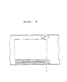
- Fig. 4 is a front view of a photographic film employed in the recording method of the present invention, wherein the disposition of recorded information on the film is illustrated.
- the photographic film 2 includes a film base, a photosensitive layer provided on one side of the film base, and a magnetically recordable transparent magnetic layer provided on the other side of the film base, wherein a perforation 1 is provided only on one side edge of the film. Recording is made only on magnetic tracks t1 and t2 on the side edge of the film devoid of perforations by a magnetic head 21 provided in a camera shown in Fig. 5.
- Fig. 6 is a block diagram showing the state of rerecording at a laboratory (or photofinisher).
- the information recorded within the camera on the recording tracks t1 and t2 of the photographic film 1 similar to that used in Example 2-1 is read by a magnetic head A using a recording system S during the time the film 2 is fed into a printer.
- the read-out information is rwritten on the tracks t1 and t2 by the magnetic head B under a constant film feed.
- Example 2-2 When the information is rewritten in Example 2-2, the clock period is changed, with the corresponding format being initialized at the same time.
- the camera information recorded within the camera on the recording tracks C1 to C3 of Fig. 23 is read by the recording system S and written on the recording tracks CO and C1 in a compacted state.
- Any of the processing operations of the Embodiment 2-1 to 2-4 is carried out as a continuous process of the process of the developing operation.
- a photographic film 1 shown in Fig. 7 may be used as a photographic film to be used in the above Embodiments.
- t1 to t4 denote magnetic recording tracks and P denotes perforations provided between adjacent photosensitive image areas indicated by double-dotted chain lines.
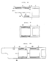
- Fig. 8 shows, in a front view, recording regions of a photographic film according to the invention of claim 12 wherein a recording extension 1 b having a width equal to the film width is provided adjacent to a lead part 1 a of the film 1.
- P denotes a perforation
- K a frame, as in the following Embodiments.
- the film information is magnetically recorded on magnetic tracks t1 to t5 at the longitudinal leading end of the photographic film shown in Fig. 8, and is read by a camera shown in Fig. 12.
- the read-out film information is magnetically recorded by the camera on the photographic film.
- Fig. 12 is a schematic view of the camera provided with magnetic heads 51, 52 for reading and recording the film information.
- Fig. 13 is a block diagram for showing the recording process by the camera.
- the film information (the information obtained upon reading, by the above mentioned camera, the film information recorded at the leading end of the film) is recorded by the above camera on a magnetic recording track t21 along the side edge of the film adjacent to the photosensitive image area (frame) of the photographic film similar to the film of the Embodiment 1 (see Fig. 9).
- the film information (the information obtained upon reading, by the above-mentioned camera, the film information recorded at the leading end of the film) is recorded on magnetic recording tracks t31 and t32 at side edge portions of a photographic film 30 similar to the film of the Embodiment 1 (see Fig. 10), the side edge portions being allocated to first and second frames K1 and K2, respectively.
- a photographic film 41 is shown which is similar to those of the Embodiments 3-1 to 3-4 except that perforations are provided between adjacent frames along the side edge of the film, as shown in Fig. 11.
- t41 to t44 denote magnetic recording tracks and each frame is denoted by a double-dotted chain line.
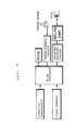
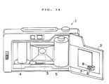
- Fig. 14 shows an overall camera system embodying the present invention, in a schematic perspective view, wherein a rear cover 2 is opened to show its inside.
- the camera system 1 includes, on its both sides at the back of a lens 3, a film takeup spool 4 and a patrone 5 accommodating therein a continuous film.
- the continuous film is designed to be moved in the both (takeup and reverse) directions between the patrone 5 and the film takeup spool 4 which are rotationally driven by electric motors, not shown.
- the continuous film is coated with a photosensitive layer containing a photosensitive material on its one surface facing the lens and with a transparent magnetic layer containing a magnetic material on its other surface.
- a protective layer is additionally formed on the upper surface of the transparent magnetic layer.
- a magnetic head 6 having electromagnetic transducer elements 7, 8 which are provided at positions capable of writing or reading magnetic recordings from or on the continuous film on closure of the rear cover 2.
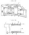
- Fig. 15 shows, in a plan view, a continuous photographic film for illustrating the track disposition for magnetic recordings on the film simultaneously with image areas (frames).
- frames image areas
- Film transport apertures 12, known as perforations, are provided in the continuous film 10 at a rate of one for each frame 13 in the vicinity of the upper rear end of the associated frame.
- One more film transport aperture 12 is provided in the vicinity of the lead part 11.
- Two tracks 14, 15 for magnetic recording are provided for each frame 13 in two lines below the associated frame.
- As for the magnetic recording writing or reading is carried out through electro- magnetic transducers 7, 8 of the magnetic head 6 on the tracks 14, 15, respectively.
- Magnetic cores of the electro-magnetic transducer elements 7, 8 supported by the magnetic head 6 are constituted by magnetic materials, such as Permally, Sendust or amorphous materials.
- the coercivity Hc of the magnetic material is selected from values of 600, 750 and 850 Oe. With a medium having these values of coercivity Hc, the magnetic head has characteristics comparable with those of the ordinary audio head.
- the track width of the magnetic head is of an order of 1 to 2 mm.
- the film transport speed in the camera system is in the order of 30 to 90 mm/s with the use of a winder and in the order of 100 to 300 mm/s with the use of a motor drive.
- the rated output of the magnetic head is as shown in Fig. 18.
- Fig. 5 is plotted for the coercivity Hc of 600 Oe and the film feed speed of 30 mm/s, the frequency-dependent characteristics curves are substantially similar to that shown in Fig. 18 for the coercivity Hc and the film transport speed in the above ranges.
- the range of the wavelength ⁇ of the clock signals, for which the signals reproduced from the clock signals and the data signals become substantially non-dependent on frequency is 25 ⁇ m or more ( ⁇ 25 ⁇ m) in which case the rated output is 3 dB.
- the wavelength ⁇ is 50 ⁇ m or more ( ⁇ 50 ⁇ m).
- the frequency range fso is given by f 90 3.6 kHz ⁇ . 4kHz.
- the preferred frequency range f 90 ' is given by
- the frequency range f 300 which may be used as the upper limit is given by
- the preferred frequency range f 300 ' is given by
- the lower limit frequency of the clock signals is found from the number of bits that may be recorded in a track length of each frame of the film and the number of information bits required of each frame. From the track length of a frame and the required number of the information bits, the wavelength ⁇ of the clock signals is calculated to be 0.6 mm or less. Thus the frequency of the clock signals is calculated to be 50 Hz or more and 150 Hz or more for the case of using the winder and the lower film transport speed of 30 mm/s and for the case of using the motor drive and the lower film transport speed of 100 mm/s, respectively.
- the usable frequency range of the clock signals in the camera system is 50 Hz to 4 kHz (or 20 ms to 0.25 ms in terms of the pulse period) and preferably 100 Hz to 2 kHz (or 10 ms to 0.5 ms in terms of the pulse period), with the use a winder, and 150 Hz to 12 kHz (or 6.7 ms to 0.08 ms in terms of the pulse period) and preferably 300 Hz to 6 kHz (or 3.3 ms to 0.16 ms in terms of the pulse period) with the use of a motor drive, respectively.
- the motor drive is used, with the film transport speed usually being in the range of from 200 mm/s to 500 mm/s.
- the range of the frequency f usable with the clock signals is similarly 300 Hz ⁇ f 2 2 kHz (or 3.3 ms to 0.05 ms in terms of the pulse period) and preferably 600 Hz ⁇ f 16 kHz (or 1.7 ms to 0.1 ms in terms of the pulse period).
- frame number data and data for frame-to-frame photographing date and photographing conditions are recorded in the first track 14 in Fig. 2.
- a signal proper to the owner of the camera such as a camera code, is recorded on the second track 15.
- Further track(s) for magnetic recording are occasionally provided in an upper region abive or in the main region of the transparent magnetic layer of a film frame 13.
- magnetic recordings may be made by the laboratory system or by a magnetic device at the film dealer after the camera user has entrusted them with the film developing operation.
- magnetic recordings indicating the data concerning film rating (specifications) may be also made by the film producer on the track(s) provided at the upper region above the frame.
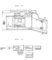
- Fig. 19 shows a camera system 1 according to an embodiment of the present invention, with a rear cover 2 of the camera opened to show its interior.
- the camera system 1 includes, in its inside, a film takeup spool 4 and a patrone 5 accommodating a continuous film therein, which are arranged on both sides and at the back of a lens 3.
- the continuous film is arranged so as to be moved in either directions between the patrone 5 and the film takeup spool 4 which are adapted to be rotated by electric motors, not shown.
- a photosensitive layer including a photosensitive material, is applied, such as by coating, to one side of the continuous film facing the lens, while a transparent magnetic layer including a magnetic material is applied, such as by coating, on the other side of the continuous film.
- a protective layer is formed on the upper surface of the transparent magnetic layer.
- a microprocessor 30 is adapted to control the diaphragm, exposure time etc. of the camera as well as the camera system in its entirety, inclusive of a film transport motor, a magnetic head etc. in a known manner.
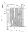
- Fig. 20 is a partial plan view of a continuous film for illustrating an array of tracks for magnetic recordings on the continuous film simultaneously with an image area (frame).
- a transport hole 12 for film transport also known as a perforation, is formed in the vicinity of an upper rear edge of each frame 13 in the continuous film 10 at a rate of one hole per frame.
- Tracks 14 to 17 for magnetic recording are provided for each frame 13, with the tracks 14 and 15 being formed at the lower edge and with the tracks 16 and 17 being formed at the upper edge of the frame 13, respectively. Magnetic recordings are written and/or read on or from the tracks 14 to 17 by the electro-magnetic transducer elements 7, 8; 7', 8' of the magnetic heads 6, 6', respectively.
- An indicating region 20 is provided in the vicinity of a lead part 11 of the film as an extension of the track 14. If the film is magnetically pre-recorded, that effect is written in the indicating region 20.
- An indicating region similar to the region 20 is provided at the similar position at the trailing end of the film. In the indicating region 20, there is also recorded data as to if the film is transported in the forward direction or in the reverse direction.
- Fig. 21 shows recording signals applied to the magnetic head for writing magnetic signals in the form of binary signals on the continuous film.
- Recording data D, clock signals C and data signals DS are shown in correspondence.
- data signals DS are outputted once when the clock signal CL assumes either a high level or a low level. Pulse transition occurs when the logical level of the recording data D is "1", so that the data signal DS turns from the high level to the low level or vice versa, i.e., from the low level to the high level. When the logical level of the recording data D is "0", no level transition of the data signal DS occurs.
- Fig. 22 shows the waveform of reproduced signals which are obtained when the magnetic signals written on the tracks 14 and 15 by recording signals having the waveforms of the clock signals and the data signals shown in Fig. 21 are reproduced by the magnetic head 6.
- the data signals are read between the peak pulses L1 to L5 corresponding to the clock signals. If peak pulses Q1, Q2 and Q3 are present in the data signal between the peak pulses of the clock signals, the logical level is determined to be "1" and, if otherwise, the logical level is determined to be "0", so that reproduced data D1 as shown in Fig. 22 are produced.
- the camera system of the present embodiment will be explained by referring again to Figs. 19 and 20.
- the camera system when the continuous film 10 is loaded in the camera system, it is first read by the magnetic head 6 whether or not formatted magnetic signals are prerecorded in the indicating region 20 of the lead part 11 of the film, and also whether or not the film transport direction is the forward direction. If the film is a new one on which formatted signals are not recorded, the camera system 1, while prewinding the continuous film 10 by transporting it from the patrone 5 to the film takeup spool 4, records clock signals on the first track 14, as well as the camera code and the frame numbers on the second track 15 by electro-magnetic transducer elements 7 and 8 of the magnetic head 6, respectively, for formatting.
- Data on the second track 15 are naturally synchronized at this time with the clock signals. If the a signal indicative of the formatted state is prerecorded on the indicating region 20, only prewinding is performed. By prerecording the clock signals in this manner, subsequent signal transmission between different systems with different film speeds becomes possible, while accurate signal recording and reproduction may be made despite fluctuations occasionally in the film transport speed in the same system.
- the microprocessor 30 calculates the film transport speed based on the detected position of the transport hole 12 for film transport or from the number of revolutions of a film transport motor. Based on the calculated film transport speed, the microprocessor 30 causes the frequency of the clock signals to be changed in accordance with the calculated film transport speed, while controlling the clock frequency so that each frame-by-frame recording region is located for each frame within a predetermined length during magnetic recording.
- the film For photographing each frame, the film is transported in reverse, that is from the takeup spool 4 to the patrone 5.
- the microprocessor 30 confirms, based on the indication in the indicating region 20, that the film transport direction is the reverse direction and that initial formatting has been completed and the film is ready for photographing.
- photographing data such as data concerning the data and time of photographing, lens stop value, shutter speed, zoom data, etc. are recorded by the electro-magnetic transducers 7', 8' of the magnetic head 6 provided adjacent to the upper edge of the film on the third and fourth tracks 16, 17 on the film.
- Data concerning the place of photographing and the photographed object etc. may also be recorded in accordance with data entered via a keyboard removably connected to the camera system by means of an accessory cable. These signals may be outputted as litters or characters on the film developed at the laboratory system.
- a frame bearing a desired frame number on the continuous film may be transported to a light exposure position by the lens for photographing at the thus selected frame position.
- one or more frames may be skipped for skip recording. It is possible in such case to take up the continuous film in the patrone 5 with one or more frames remaining unexposed and to transfer the film from the camera to another camera to effect photographing of the unexposed frame or frames by such another camera system.
- desired data recorded by the camera system are read out in synchronism with clocks recorded on the first track 14. These data may be used for setting developing or printing conditions, grasping customer data, or for requesting printing only of preselected frames. It is also possible with the film dealer or developing laboratory to record data necessary by the dealer or developing laboratory in the photographed frames on the film. In this case, magnetic recording is made on the transparent magnetic layer on the entire film surface except those portions on which magnetic signals have been recorded, for example, within the frame area.
- upper two and lower two tracks on both sides of each frame are reserved in the present embodiment for magnetic recording which should be made by the camera system
- the number of tracks may naturally be selected in any desired manner. For example, only two lower tracks may be provided so that clock signals are recorded on one of the tracks and data are recorded on the other track. Alternatively, three tracks may be provided on the side edge of the film devoid of perforation(s) so that clock signals are recorded on one of the tracks and data are recorded on the other tracks.
- the perforation 12 is provided in the present embodiment at the upper rear end of each frame, the perforation may be provided at the inter mediate region of each frame, or the perforation may be eliminated so that the recording track at the upper side edge of the frame has a length equal to the frame length, in which case a track at the upper side of the frame may be used as a track for initial formatting for a new film.
- the magnetic recording region(s) at the film side edge(s) per photosensitive image area is increased in area and the magnetic recording track at the side edge of the film are rendered continuous and of a sufficient length since each of the perforations is provided between the adjacent photosensitive image areas at at least a side edge of the film in a side edge region lying between the photosensitive image areas and it extends throughout the overall length of the side edge region of the film adjacent to the image area at least one side edge of the film.
- the camera information recorded on the film under unstable states may be converted into and recorded as reliable and stable magnetically recorded information, thereby enabling the information to be reread subsequently, above all, after development or after printing, with improved reliability, for accurately reproducing the information.
- the load on the mechanism of the reading device may be relieved during rereading.
- the film information can be recorded efficiently.
- the most crucial film information may be reliably and promptly read at the start of film take-up on loading the film on the camera.
- the film in its entirety can be taken up, and the film information may be recorded at desired positions at a desired number of repetition.
- the film information since the film information may be recorded a desired number of time at succeeding film portions based on the information read out at the leading end portion of the film, the film information, recorded at locations other than the leading end portion, may occasionally be read frame by frame to make photographing as the film information is checked.
- a sufficient amount of the film information is recorded at the leading end portion of the film which may be used as a spare recording region for other informations. Since the same film information may be recorded a desired number of times, reading errors of the film information may be prevented from occuring.
- the advantage to be accuired by recording the film information at the longitudinal leading end of the film has been discussed in connection with the first Sub-Aspect.
- photographing may be made as the film information is read frame by frame to check the film information. Also, photographing may be started at a desired frame of the film thereupon to prevent misreading of the film information.
- the present invention provides a camera system in which prescribed magnetic signals may be recorded on a new continuous film, simultaneously with prewinding, when the film is loaded, so that initial film formatting becomes possible, as a result of which data such as those for photographing conditions and data to be recorded during prewinding of the film may be recorded separately for reducing the volume of data to be recorded after light exposure, and in which the film may be transported at an appropriate transport speed for the camera system while a predetermined constant recording density is maintained within the range of performance of various devices provided in the camera system, such as a microprocessor, buffer, or a magnetic system.
- photographing may be made on an arbitrarily selected frame so that the film may be transferred from one camera to another for photographing for eliminating film loss and consequent wasteful printing.
- clock signals are included in the magnetic signals, signal transmission between different systems having different film transport speeds, such as camera system and a laboratory system, becomes possible, while, in addition, in case of film transport speed fluctuations in a given system, magnetic signals may be recorded and reproduced accurately with a reasonably high recording density.
Landscapes
- Physics & Mathematics (AREA)
- General Physics & Mathematics (AREA)
- Camera Data Copying Or Recording (AREA)
- Recording Or Reproducing By Magnetic Means (AREA)
Applications Claiming Priority (10)
| Application Number | Priority Date | Filing Date | Title |
|---|---|---|---|
| JP242796/90 | 1990-09-14 | ||
| JP242797/90 | 1990-09-14 | ||
| JP24279790 | 1990-09-14 | ||
| JP24279990 | 1990-09-14 | ||
| JP242799/90 | 1990-09-14 | ||
| JP242798/90 | 1990-09-14 | ||
| JP24280090 | 1990-09-14 | ||
| JP242800/90 | 1990-09-14 | ||
| JP24279890 | 1990-09-14 | ||
| JP24279690 | 1990-09-14 |
Publications (2)
| Publication Number | Publication Date |
|---|---|
| EP0475447A2 true EP0475447A2 (de) | 1992-03-18 |
| EP0475447A3 EP0475447A3 (en) | 1992-09-23 |
Family
ID=27530076
Family Applications (1)
| Application Number | Title | Priority Date | Filing Date |
|---|---|---|---|
| EP9191115592A Ceased EP0475447A3 (en) | 1990-09-14 | 1991-09-13 | Magnetically recordable photographic film, recording method and system therefor and camera-laboratory system |
Country Status (2)
| Country | Link |
|---|---|
| US (3) | US5835802A (de) |
| EP (1) | EP0475447A3 (de) |
Cited By (6)
| Publication number | Priority date | Publication date | Assignee | Title |
|---|---|---|---|---|
| EP0610933A1 (de) * | 1993-02-12 | 1994-08-17 | Canon Kabushiki Kaisha | Kamera, geeignet für photographische Filme, die bestückt sind mit magnetischen Speicherabschnitten |
| FR2716985A1 (fr) * | 1994-03-04 | 1995-09-08 | Aaton Sa | Format d'enregistrement d'images. |
| EP0696756A3 (de) * | 1994-08-08 | 1996-04-24 | Nippon Kogaku Kk | Vorrichtung zur magnetischen Datenaufzeichnung |
| US5761555A (en) * | 1992-06-30 | 1998-06-02 | Canon Kabushiki Kaisha | Camera having magnetic head |
| US5949551A (en) * | 1997-04-25 | 1999-09-07 | Eastman Kodak Company | Image handling method using different image resolutions |
| US6069712A (en) * | 1997-01-31 | 2000-05-30 | Eastman Kodak Company | Image handling method and system incorporating coded instructions |
Families Citing this family (4)
| Publication number | Priority date | Publication date | Assignee | Title |
|---|---|---|---|---|
| EP0584583B1 (de) | 1992-08-03 | 1998-10-07 | Fuji Photo Film Co., Ltd. | Verfahren zur Herstellung eines photographischen Filmes und einer photographischen Filmkassette |
| EP1670235A1 (de) | 1999-12-28 | 2006-06-14 | Sony Corporation | Tragbares Musikwiedergabegerät |
| DE60044179D1 (de) | 1999-12-28 | 2010-05-27 | Sony Corp | System und Verfahren für den kommerziellen Verkehr von Bildern |
| US6553187B2 (en) * | 2000-12-15 | 2003-04-22 | Michael J Jones | Analog/digital camera and method |
Family Cites Families (13)
| Publication number | Priority date | Publication date | Assignee | Title |
|---|---|---|---|---|
| US4783674A (en) * | 1986-10-13 | 1988-11-08 | Minolta Camera Kabushiki Kaisha | Photographic camera with built-in E2PROM |
| DE3728655A1 (de) * | 1987-08-27 | 1989-03-09 | Thomson Brandt Gmbh | Verfahren und/oder einrichtung zum demodulieren eines biphasesignales |
| US5411864A (en) * | 1987-11-05 | 1995-05-02 | Genentech, Inc. | Method of purifying recombinant proteins from corresponding host cell proteins |
| BR8807290A (pt) * | 1987-11-12 | 1990-03-27 | Unilever Nv | Composicao de limpeza aquosa e tixotropica e processo para prepara-la |
| US4912467A (en) * | 1988-06-14 | 1990-03-27 | Eastman Kodak Company | Three-part encoder circuit |
| US4860037A (en) * | 1988-09-12 | 1989-08-22 | Eastman Kodak Company | Film cassette with magnetic film leader |
| US5006873A (en) * | 1988-10-07 | 1991-04-09 | Eastman Kodak Company | Implicit mid roll interrupt protection code for camera using dedicated magnetic tracks on film |
| US4965626A (en) * | 1988-10-07 | 1990-10-23 | Eastman Kodak Company | Printing and makeover process for magnetically encodable film with dedicated magnetic tracks |
| US4977419A (en) * | 1988-10-07 | 1990-12-11 | Eastman Kodak Company | Self-clocking encoding/decoding film information exchange system using dedicated magnetic tracks on film |
| US4965575A (en) * | 1988-10-07 | 1990-10-23 | Eastman Kodak Company | Data alignment circuit and method for self-clocking encoded data |
| US5130728A (en) * | 1989-10-27 | 1992-07-14 | Nikon Corporation | Information recordable camera |
| US5255031A (en) * | 1989-11-13 | 1993-10-19 | Fuji Photo Film Co., Ltd. | Data-retainable photographic film cartridge |
| US5231451A (en) * | 1990-09-12 | 1993-07-27 | Fuji Photo Film Co., Ltd. | Method of recording information onto a photographic film and apparatus therefor |
-
1991
- 1991-09-13 EP EP9191115592A patent/EP0475447A3/en not_active Ceased
-
1996
- 1996-04-17 US US08/633,555 patent/US5835802A/en not_active Expired - Fee Related
-
1997
- 1997-07-21 US US08/897,978 patent/US6201934B1/en not_active Expired - Fee Related
-
2001
- 2001-02-01 US US09/774,636 patent/US6336006B2/en not_active Expired - Fee Related
Cited By (9)
| Publication number | Priority date | Publication date | Assignee | Title |
|---|---|---|---|---|
| US5761555A (en) * | 1992-06-30 | 1998-06-02 | Canon Kabushiki Kaisha | Camera having magnetic head |
| EP0610933A1 (de) * | 1993-02-12 | 1994-08-17 | Canon Kabushiki Kaisha | Kamera, geeignet für photographische Filme, die bestückt sind mit magnetischen Speicherabschnitten |
| US6195512B1 (en) | 1993-02-12 | 2001-02-27 | Canon Kabushiki Kaisha | Camera adapted for films provided with magnetic storage portions |
| FR2716985A1 (fr) * | 1994-03-04 | 1995-09-08 | Aaton Sa | Format d'enregistrement d'images. |
| EP0696756A3 (de) * | 1994-08-08 | 1996-04-24 | Nippon Kogaku Kk | Vorrichtung zur magnetischen Datenaufzeichnung |
| US5856889A (en) * | 1994-08-08 | 1999-01-05 | Nikon Corporation | Magnetic data recording apparatus using pulse position modulation |
| US6069712A (en) * | 1997-01-31 | 2000-05-30 | Eastman Kodak Company | Image handling method and system incorporating coded instructions |
| US6283646B1 (en) | 1997-01-31 | 2001-09-04 | Eastman Kodak Company | Image handling method and system incorporating coded instructions |
| US5949551A (en) * | 1997-04-25 | 1999-09-07 | Eastman Kodak Company | Image handling method using different image resolutions |
Also Published As
| Publication number | Publication date |
|---|---|
| US20010007614A1 (en) | 2001-07-12 |
| EP0475447A3 (en) | 1992-09-23 |
| US6201934B1 (en) | 2001-03-13 |
| US6336006B2 (en) | 2002-01-01 |
| US5835802A (en) | 1998-11-10 |
Similar Documents
| Publication | Publication Date | Title |
|---|---|---|
| EP0424972B1 (de) | Filmtransporteinrichtung mit magnetischer Informationsaufzeichnung | |
| US4443077A (en) | Film cassette and a photographing device using the same | |
| US5005031A (en) | Camera apparatus for magnetically recording on film | |
| US5344730A (en) | Method of recording information on a photographic film | |
| US5325138A (en) | Camera using film with magnetic record portion | |
| US5835802A (en) | Magnetically recordable photographic film recording method and system therefor and camera laboratory system | |
| JPH04171433A (ja) | 磁気記憶部付フィルムを用いるカメラ | |
| JPH05119386A (ja) | カメラ用磁気ヘツド | |
| EP0679927B1 (de) | Photoapparat mit Magnetaufzeichnungskopf | |
| US5502527A (en) | Camera capable of magnetic recording | |
| US5724623A (en) | Camera using a film with a magnetic memory portion | |
| EP0438480B1 (de) | Photographische Kamera mit magnetischer Aufzeichung auf dem Film | |
| US5181058A (en) | Camera having magnetic head for demagnetizing and recording in demagnetization pattern | |
| JPH04362929A (ja) | カメラシステム、記録システム及びラボシステム | |
| US4146312A (en) | Sound motion picture camera and sound motion picture system | |
| US5898476A (en) | Data format for magnetically coated film | |
| JP2930777B2 (ja) | カメラ | |
| JPH04291249A (ja) | 写真フィルム及び情報記録方法 | |
| JPH04246639A (ja) | 磁気記憶部付フィルムを用いるカメラ | |
| JP3050656B2 (ja) | カメラの磁気再生装置 | |
| JPH04123058A (ja) | 写真用フイルムのデータ併合方法及び装置 | |
| JPH05346616A (ja) | カメラの磁気情報記録装置 | |
| JPH05150322A (ja) | カメラの磁気再生装置 | |
| JPH063741A (ja) | カメラの磁気情報記録装置 | |
| JPH04246628A (ja) | 磁気記憶部付フィルムを用いるカメラ |
Legal Events
| Date | Code | Title | Description |
|---|---|---|---|
| PUAI | Public reference made under article 153(3) epc to a published international application that has entered the european phase |
Free format text: ORIGINAL CODE: 0009012 |
|
| AK | Designated contracting states |
Kind code of ref document: A2 Designated state(s): DE GB NL |
|
| PUAL | Search report despatched |
Free format text: ORIGINAL CODE: 0009013 |
|
| AK | Designated contracting states |
Kind code of ref document: A3 Designated state(s): DE GB NL |
|
| 17P | Request for examination filed |
Effective date: 19921216 |
|
| 17Q | First examination report despatched |
Effective date: 19941207 |
|
| STAA | Information on the status of an ep patent application or granted ep patent |
Free format text: STATUS: THE APPLICATION HAS BEEN REFUSED |
|
| 18R | Application refused |
Effective date: 19971214 |