EP0476690B1 - Verfahren zum steuern eines seriellen Punktanschlagdruckers - Google Patents
Verfahren zum steuern eines seriellen Punktanschlagdruckers Download PDFInfo
- Publication number
- EP0476690B1 EP0476690B1 EP91116039A EP91116039A EP0476690B1 EP 0476690 B1 EP0476690 B1 EP 0476690B1 EP 91116039 A EP91116039 A EP 91116039A EP 91116039 A EP91116039 A EP 91116039A EP 0476690 B1 EP0476690 B1 EP 0476690B1
- Authority
- EP
- European Patent Office
- Prior art keywords
- platen
- wires
- tips
- print head
- Prior art date
- Legal status (The legal status is an assumption and is not a legal conclusion. Google has not performed a legal analysis and makes no representation as to the accuracy of the status listed.)
- Expired - Lifetime
Links
- 238000000034 method Methods 0.000 title claims description 9
- 230000003111 delayed effect Effects 0.000 claims description 3
- 230000003116 impacting effect Effects 0.000 claims description 3
- 230000010355 oscillation Effects 0.000 description 5
- 230000000644 propagated effect Effects 0.000 description 3
- 238000010276 construction Methods 0.000 description 2
- 238000003491 array Methods 0.000 description 1
- 230000001934 delay Effects 0.000 description 1
- 238000010586 diagram Methods 0.000 description 1
- 125000000383 tetramethylene group Chemical group [H]C([H])([*:1])C([H])([H])C([H])([H])C([H])([H])[*:2] 0.000 description 1
Images




Classifications
-
- B—PERFORMING OPERATIONS; TRANSPORTING
- B41—PRINTING; LINING MACHINES; TYPEWRITERS; STAMPS
- B41J—TYPEWRITERS; SELECTIVE PRINTING MECHANISMS, i.e. MECHANISMS PRINTING OTHERWISE THAN FROM A FORME; CORRECTION OF TYPOGRAPHICAL ERRORS
- B41J2/00—Typewriters or selective printing mechanisms characterised by the printing or marking process for which they are designed
- B41J2/22—Typewriters or selective printing mechanisms characterised by the printing or marking process for which they are designed characterised by selective application of impact or pressure on a printing material or impression-transfer material
- B41J2/23—Typewriters or selective printing mechanisms characterised by the printing or marking process for which they are designed characterised by selective application of impact or pressure on a printing material or impression-transfer material using print wires
- B41J2/235—Print head assemblies
- B41J2/25—Print wires
- B41J2/255—Arrangement of the print ends of the wires
-
- B—PERFORMING OPERATIONS; TRANSPORTING
- B41—PRINTING; LINING MACHINES; TYPEWRITERS; STAMPS
- B41J—TYPEWRITERS; SELECTIVE PRINTING MECHANISMS, i.e. MECHANISMS PRINTING OTHERWISE THAN FROM A FORME; CORRECTION OF TYPOGRAPHICAL ERRORS
- B41J2/00—Typewriters or selective printing mechanisms characterised by the printing or marking process for which they are designed
- B41J2/22—Typewriters or selective printing mechanisms characterised by the printing or marking process for which they are designed characterised by selective application of impact or pressure on a printing material or impression-transfer material
- B41J2/23—Typewriters or selective printing mechanisms characterised by the printing or marking process for which they are designed characterised by selective application of impact or pressure on a printing material or impression-transfer material using print wires
- B41J2/30—Control circuits for actuators
Definitions
- the present invention relates to a method of operating a dot impact type serial printer applicable to, for example, a computer output terminal.
- the surface of the platen Since the selected wires of each array impact against the platen at the same time, the surface of the platen is elastically deformed to a noticeable extent. Such deformations of the platen are sequentially propagated along the platen and produce surface waves having various frequency components. The surface waves are repetitively reflected at the ends of the platen and propagated back and forth along the surface of the platen. While the surface waves are so propagated back and forth, a standing wave, having the same period as the time in which the surface wave passes along the length of the platen, is generated in the surface of the platen.
- the dot impact type serial printer continuously impacts the print wires thereof against the platen at a predetermined period.
- the surface waves are continuously generated and, when the impacting period is identical with the period of the standing wave, the surface waves cooperate with the standing wave.
- surface oscillation stably occurs on the surface of the platen. Such surface oscillation constitutes the source of unpleasant noise.
- JP-A-62-278055 discloses a method of operating a dot impact type serial printer according to the preamble of claim 1 in which a plurality of printing pins in a print head are successively driven at an interval determined by dividing the drive period per pin by the number of the printing pins.
- the interval T for driving the successive printing pins is determined by the scanning speed in the spacing direction of the head, the vertical distance between neighboring wires and the inclination angle.
- successive ones of the print wires are driven at the above-mentioned interval to impact against the platen.
- the amplitude of each surface wave is reduced.
- the interval is less than one half of the time in which the surface waves of the platen pass the platen in the lengthwise direction, the phase differences among the surface waves are smaller than 180 degrees of a basic component of the standing wave.
- the surface waves therefore, cancel one another and do not cooperate with one another. This is successful in reducing the surface oscillation and, therefore, the raise, to a negligible degree.
- a serial printer to be operated according to the present invention includes a carriage 2.
- the carriage 2 is mounted on parallel guide shafts 4a and 4b and movable therealong in a reciprocating motion, as indicated by an arrow H in the figure.
- a print head 1 and an ink ribbon cassette 1' are mounted on the carriage 2.
- a drive pulley 8a is mounted on the output shaft of a motor 6.
- a belt 7 is passed over the drive pulley 8a and a driven pulley 8b in a loop configuration, and the carriage 2 is affixed to the belt 7.
- the carriage 2 i.e., the print head 1 moves at a speed of 111 cps (characters per second) which is equal to 11.1 inches per second.
- the print head 1 faces a cylindrical platen 5 which extends in parallel to the above-mentioned direction H.
- a recording medium in the form of a sheet S is wound around the platen 5.
- the print head 1 has twelve print wires on the printing surface thereof, as will be described specifically later.
- the twelve print wires are selectively thrusted out toward the platen 5 in response to a print wire drive signal fed to the print head 1 over a flat cable 3.
- An ink ribbon is fed out of the cassette 1' to the printing surface of the print head 1.
- the print head 1 While the print head 1 is moved in the direction H by the motor 6, the print wires of the head 1 are selectively driven to print a desired character or image on the sheet S.
- the platen 5 has a length L of 426 millimeters and is made of SBR (Stylene Butylene Rubber) having a hardness of 98 degrees.
- print wires 11a, 11b, 11c, 11d, ..., 11l are arranged in a substantially vertical array on the printing surface 11 of the print head 1 which faces the platen 5.
- the line formed by the tips of the wires 11a - 11l is inclined relative to the vertical line V which is perpendicular to the moving direction H of the print head 1.
- the printing surface 11 of the print head 1 appears as shown in Fig. 2(b) when viewed from the platen 5 side.
- the print wires 11a - 11l are arranged at the same pitch Pv of 1/180 inch in the direction of the vertical line V.
- the uppermost wire 11a and the lowermost wire 11l are spaced apart from each other by a distance Ph of 1/195 inch in the moving direction H of the print head 1.
- the wires 11b, 11c, 11d, .... intervening between the wires 11a and 11l are spaced apart by the same pitch in the direction H.
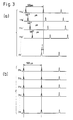
- Figs. 3(a) and 3(b) relate to the printer of the present invention and a conventional printer, respectively.
- the drive period per one wire is 500 microseconds
- the platen roller 5 is made of SBR and has a length L of 426 millimeters and a hardness of 98 degrees. Then, the surface wave passes the surface of the platen 5 in the lengthwise direction L in 500 microseconds.
- the printer operated according to the present invention drives successive ones of the wires 11a - 11l at the same interval and a time lag of t which is 500/12 microseconds, as represented by wave-forms 11'a - 11'l.
- the time lag of 500/12 microseconds is one-twelfth, i.e., less than one half of the time in which the surface wave passes the platen 5 in the lengthwise direction L. Consequently, the surface waves cancel each other to suppress the surface oscillation of the platen 5 and, therefore, the noise.
- Fig. 4 shows a specific construction of circuitry for generating the above-mentioned drive timings 11'a - 11'l.
- the circuitry has a print timing generating circuit 21 which generates a print timing signal 21S for driving the print wires 11a - 11l.
- Delay circuits 22a, 22b, 22c, 22d, ..., 22l each delays the print timing signal 21S and delivers the resulting delayed signal to associated one of print wire drive circuits 23a, 23b, 23c, 23d, ..., 23l.
- a print pattern generating circuit 24 generates a print pattern signal 24S in response to data fed thereto from a font ROM 25.
- the print pattern signal 24S is fed to particular ones of the delay circuits 22a - 22l via a print pattern control circuit 26.
- a delay control circuit 27 controls the delay time of each of the delay circuits 22a - 22l so that particular ones of the delay circuits 22a - 22l, when selected by the print pattern control circuit 26, delay the print timing signal 21S by a respective delay time and, then, deliver the delayed signal to associated one of the print wire drive circuits 23a - 23l.
- the print pattern control circuit 26 starts operating in response to the print timing signal 21S and feeds, based on the print pattern, a selection signal 26S to particular ones of the delay circuits 22a - 22l which are associated with the wires to be driven.
- drive signals 11'a - 11'l are sequentially applied to the print head 1, causing the print wires 11a - 11l to drive in the order shown in Fig. 3(a). Since the print head 1 sequentially drives the wires 11a - 11l while moving in the forward direction Hf, a line parallel to the vertical line V is printed on the sheet S.
- the delay control circuit 27 sets delay times of 11t, 10t, 9t, 8t, ..., 0 in the delay circuits 22a, 22b, 22c, 22d, ..., 22l, respectively.
- the drive signals 11'l - 11'a are sequentially applied to the print head 1, causing the print wires 11l - 11a to drive in the opposite order to the order shown in Fig. 3(a).
- the head 1, therefore, prints a line parallel to the vertical line V on the sheet S.
- all the print wires 11a - 11l are driven to print a vertical line on the sheet S.
- the wires 11a - 11l may be selectively driven on the basis or a pattern to be printed, i.e., they can print any desired pattern on the sheet S.
- Figs. 5(a) and 5(b) show the waveforms of acoustic pressure of the printer operated according to the present invention and the conventionally operated printer, respectively, each measured at the beginning of a printing operation at a distance of 200 millimeters just above the printing surface 11.
- the waveform 32 of the conventionally operated printer sequentially increases in amplitude while the waveform 31 of the printer operated according to the present invention has small amplitudes.
- the conventionally operated printer and the printer operated according to the present invention were measured to be 97 dB(A) and 85 dB(A), respectively.
- the present invention provides a method for operating a dot impact type serial printer which reduces noise by driving successive ones of print wires thereof at an interval less than one-half of the time in which the surface wave of a platen passes the platen in the lengthwise direction of the latter.
Landscapes
- Dot-Matrix Printers And Others (AREA)
- Accessory Devices And Overall Control Thereof (AREA)
- Handling Of Sheets (AREA)
Claims (4)
- Verfahren zum Betrieb eines seriellen Punktanschlagdruckers mit:
einer Schreibwalze (5) zum Haltern eines Blattes darauf;
einem Druckkopf (1), der mehrere Drucknadeln (11a bis 11l) enthält, deren Spitzen in einer Druckfläche des Druckkopfes angeordnet sind, wobei der Druckkopf auf die Spitzen der Drucknadeln Druck ausübt, um ein Bild zu drucken; und
einer Druckantriebseinrichtung (21, 22, 23, 26) für den sukzessiven Antrieb der mehreren Drucknadeln in einem Intervall (t),
dadurch gekennzeichnet, daß
das Intervall (t) so bestimmt ist, daß es weniger als die Hälfte der Zeit beträgt, in welcher eine Oberflächenwelle die Schreibwalze in der Längsrichtung (H) der Schreibwalze durchläuft, was Phasendifferenzen kleiner als 180° zwischen den Oberflächenwellen verursacht, die in der Längsrichtung der Schreibwalze laufen und von jeder Spitze der auf die Schreibwalze schlagenden Drucknadeln verursacht werden, wodurch die Oberflächenwellen sich gegenseitig auslöschen. - Verfahren nach Anspruch 1, dadurch gekennzeichnet daß der Druckkopf (1) ein Bild druckt, während er in der Längsrichtung (H) der Schreibwalze (5) angetrieben wird, wobei die Spitzen der mehreren Drucknadeln (11a bis 11l) in einer Gruppe angeordnet sind, welche relativ zu einer Richtung (V) geneigt ist, die senkrecht zu der Längsrichtung (H) steht.
- Verfahren nach Anspruch 1 oder 2, dadurch gekennzeichnet, daß die Druckantriebseinrichtung aufweist:
eine Druckzeitablaufsignal-Erzeugungsschaltung (21) zum Erzeugen eines Druckzeitablaufsignals(21S);und
mehrere Verzögerungsschaltungen (22a bis 22l), welche jeweils einer von den mehreren Drucknadeln (11a bis 11l) zugeordnet sind, um beim Empfang des Druckzeitablaufsignals (21S) eine entsprechende Verzögerungszeit (0 bis 11t) zu erzeugen und ein verzögertes Druckzeitablaufsignal (11 a' bis 11 l') als ein Nadelantriebssignal auszugeben. - Verfahren nach Anspruch 3, dadurch gekennzeichnet, daß es ferner eine Verzögerungssteuerschaltung (27) zum Einstellen der jeweiligen Verzögerungszeiten (0 bis 11t) für jede der mehreren Verzögerungsschaltungen (22a bis 22l) aufweist.
Applications Claiming Priority (2)
| Application Number | Priority Date | Filing Date | Title |
|---|---|---|---|
| JP253724/90 | 1990-09-21 | ||
| JP2253724A JP3001244B2 (ja) | 1990-09-21 | 1990-09-21 | ドットインパクトプリンタの印字方式 |
Publications (2)
| Publication Number | Publication Date |
|---|---|
| EP0476690A1 EP0476690A1 (de) | 1992-03-25 |
| EP0476690B1 true EP0476690B1 (de) | 1995-05-24 |
Family
ID=17255263
Family Applications (1)
| Application Number | Title | Priority Date | Filing Date |
|---|---|---|---|
| EP91116039A Expired - Lifetime EP0476690B1 (de) | 1990-09-21 | 1991-09-20 | Verfahren zum steuern eines seriellen Punktanschlagdruckers |
Country Status (4)
| Country | Link |
|---|---|
| US (1) | US5310270A (de) |
| EP (1) | EP0476690B1 (de) |
| JP (1) | JP3001244B2 (de) |
| DE (1) | DE69109985T2 (de) |
Families Citing this family (7)
| Publication number | Priority date | Publication date | Assignee | Title |
|---|---|---|---|---|
| US5385414A (en) * | 1992-03-23 | 1995-01-31 | Seiko Epson Corporation | Printing head and its drive timing control circuit for impact printer |
| JPH06316089A (ja) * | 1993-05-06 | 1994-11-15 | Nec Corp | シリアルプリンタ用印字タイミング制御方式 |
| JP2541096B2 (ja) * | 1993-05-06 | 1996-10-09 | 日本電気株式会社 | シリアルプリンタ用印字周期設定方法 |
| JP3277264B2 (ja) * | 1993-08-19 | 2002-04-22 | 沖電気工業株式会社 | ドット印字ヘッド及びその印字制御方法 |
| US6850893B2 (en) * | 2000-01-14 | 2005-02-01 | Saba Software, Inc. | Method and apparatus for an improved security system mechanism in a business applications management system platform |
| US6601513B1 (en) * | 1999-05-25 | 2003-08-05 | Seiko Precision, Inc. | Motor control method and apparatus, time recorder having same and impact type printing apparatus |
| JP4716240B2 (ja) * | 2001-03-30 | 2011-07-06 | マックス株式会社 | 印字方法、印字装置およびタイムレコーダ |
Family Cites Families (11)
| Publication number | Priority date | Publication date | Assignee | Title |
|---|---|---|---|---|
| DE2437454B2 (de) * | 1974-08-03 | 1976-12-23 | Philips Patentverwaltung Gmbh, 2000 Hamburg | Druckwiderlager fuer druckwerke |
| JPS526418A (en) * | 1975-07-07 | 1977-01-18 | Toshiba Corp | Dot system printer |
| JPS527631A (en) * | 1975-07-08 | 1977-01-20 | Omron Tateisi Electronics Co | Dot printer |
| IT1119227B (it) * | 1979-10-17 | 1986-03-03 | Olivetti & Co Spa | Dispositivo di stampa a punti per macchina contabile terminale telescrivente e simile macchina per ufficio |
| JPS5859860A (ja) * | 1981-10-07 | 1983-04-09 | Ricoh Co Ltd | ドツトプリンタ装置 |
| JPS5955761A (ja) * | 1982-09-27 | 1984-03-30 | Fujitsu Ltd | ドツト・プリンタの印字方式 |
| JPS60159066A (ja) * | 1984-01-31 | 1985-08-20 | Tenshiyou Denki Kogyo Kk | ドツトプリンタ |
| DE3538762A1 (de) * | 1985-10-31 | 1987-05-14 | Mannesmann Ag | Drucker, insbes. matrixdrucker der nadelbauart |
| EP0249419B1 (de) * | 1986-06-10 | 1991-01-30 | Bridgestone Corporation | Schreibwalze |
| JPS6372558A (ja) * | 1987-08-12 | 1988-04-02 | Seiko Epson Corp | 印字制御方法 |
| DE3907080A1 (de) * | 1989-03-04 | 1990-09-06 | Philips Patentverwaltung | Matrixdrucker |
-
1990
- 1990-09-21 JP JP2253724A patent/JP3001244B2/ja not_active Expired - Lifetime
-
1991
- 1991-09-20 EP EP91116039A patent/EP0476690B1/de not_active Expired - Lifetime
- 1991-09-20 DE DE69109985T patent/DE69109985T2/de not_active Expired - Fee Related
-
1993
- 1993-05-05 US US08/056,949 patent/US5310270A/en not_active Expired - Fee Related
Also Published As
| Publication number | Publication date |
|---|---|
| JP3001244B2 (ja) | 2000-01-24 |
| US5310270A (en) | 1994-05-10 |
| EP0476690A1 (de) | 1992-03-25 |
| DE69109985D1 (de) | 1995-06-29 |
| DE69109985T2 (de) | 1995-10-19 |
| JPH04212872A (ja) | 1992-08-04 |
Similar Documents
| Publication | Publication Date | Title |
|---|---|---|
| EP0518670A3 (en) | Ink jet recording apparatus | |
| JPH0691882A (ja) | インク・ジェット・プリンタの操作方法 | |
| US6386665B2 (en) | Ink-jet recording apparatus | |
| US20020054311A1 (en) | Recording device | |
| US5310270A (en) | Printing method for dot impact type serial printer | |
| EP1120261B1 (de) | Falschregistrierungskorrektur für das drucken in zwei richtungen mit vermindertem fehlereinfluss durch vertikales abtasten | |
| US6106101A (en) | Print head assembly | |
| JP2000094753A (ja) | 記録装置及び記録装置の制御方法 | |
| US5923345A (en) | Multi-printing-mode control circuit for an ink ejecting printing apparatus | |
| US5937145A (en) | Method and apparatus for improving ink-jet print quality using a jittered print mode | |
| US6097409A (en) | Image recording apparatus | |
| JPH11334149A (ja) | 印字位置補正方法および印字装置 | |
| EP0454412B1 (de) | Punktmatrixdrucker mit Druckgeräuschdämpfung | |
| EP0173952A1 (de) | Punktmatrix-Schlagdrucker | |
| US6428137B1 (en) | Inkjet printing method and device | |
| US5483268A (en) | Method for driving ink jet print head | |
| EP0795838A2 (de) | Vorrichtung und Verfahren für verflochtenen Druck | |
| JPH10109442A (ja) | 多重素子プリンタ | |
| JPH0698789B2 (ja) | シリアルドツトプリンタ | |
| JPH10181099A (ja) | インパクトプリンタの制御方法 | |
| JP2000094754A (ja) | 記録装置 | |
| JPS592855A (ja) | インクジエツトプリンタ | |
| JPH1148467A (ja) | インクジェット記録装置 | |
| JPH07323609A (ja) | 画像形成装置及び方法 | |
| US5717447A (en) | Method of driving ink jet printing head |
Legal Events
| Date | Code | Title | Description |
|---|---|---|---|
| PUAI | Public reference made under article 153(3) epc to a published international application that has entered the european phase |
Free format text: ORIGINAL CODE: 0009012 |
|
| 17P | Request for examination filed |
Effective date: 19911016 |
|
| AK | Designated contracting states |
Kind code of ref document: A1 Designated state(s): DE FR GB |
|
| 17Q | First examination report despatched |
Effective date: 19920603 |
|
| GRAA | (expected) grant |
Free format text: ORIGINAL CODE: 0009210 |
|
| AK | Designated contracting states |
Kind code of ref document: B1 Designated state(s): DE FR GB |
|
| REF | Corresponds to: |
Ref document number: 69109985 Country of ref document: DE Date of ref document: 19950629 |
|
| ET | Fr: translation filed | ||
| PLBE | No opposition filed within time limit |
Free format text: ORIGINAL CODE: 0009261 |
|
| STAA | Information on the status of an ep patent application or granted ep patent |
Free format text: STATUS: NO OPPOSITION FILED WITHIN TIME LIMIT |
|
| 26N | No opposition filed | ||
| PGFP | Annual fee paid to national office [announced via postgrant information from national office to epo] |
Ref country code: FR Payment date: 20010911 Year of fee payment: 11 |
|
| PGFP | Annual fee paid to national office [announced via postgrant information from national office to epo] |
Ref country code: GB Payment date: 20010919 Year of fee payment: 11 |
|
| PGFP | Annual fee paid to national office [announced via postgrant information from national office to epo] |
Ref country code: DE Payment date: 20011009 Year of fee payment: 11 |
|
| REG | Reference to a national code |
Ref country code: GB Ref legal event code: IF02 |
|
| PG25 | Lapsed in a contracting state [announced via postgrant information from national office to epo] |
Ref country code: GB Free format text: LAPSE BECAUSE OF NON-PAYMENT OF DUE FEES Effective date: 20020920 |
|
| PG25 | Lapsed in a contracting state [announced via postgrant information from national office to epo] |
Ref country code: DE Free format text: LAPSE BECAUSE OF NON-PAYMENT OF DUE FEES Effective date: 20030401 |
|
| GBPC | Gb: european patent ceased through non-payment of renewal fee |
Effective date: 20020920 |
|
| PG25 | Lapsed in a contracting state [announced via postgrant information from national office to epo] |
Ref country code: FR Free format text: LAPSE BECAUSE OF NON-PAYMENT OF DUE FEES Effective date: 20030603 |
|
| REG | Reference to a national code |
Ref country code: FR Ref legal event code: ST |