EP0476874B1 - Struktur für Kraftfahrzeugfenster-Führungskanal - Google Patents
Struktur für Kraftfahrzeugfenster-Führungskanal Download PDFInfo
- Publication number
- EP0476874B1 EP0476874B1 EP91307992A EP91307992A EP0476874B1 EP 0476874 B1 EP0476874 B1 EP 0476874B1 EP 91307992 A EP91307992 A EP 91307992A EP 91307992 A EP91307992 A EP 91307992A EP 0476874 B1 EP0476874 B1 EP 0476874B1
- Authority
- EP
- European Patent Office
- Prior art keywords
- window
- guide
- window guide
- extended portion
- run
- Prior art date
- Legal status (The legal status is an assumption and is not a legal conclusion. Google has not performed a legal analysis and makes no representation as to the accuracy of the status listed.)
- Expired - Lifetime
Links
- 239000011347 resin Substances 0.000 claims description 12
- 229920005989 resin Polymers 0.000 claims description 12
- 238000001746 injection moulding Methods 0.000 claims description 3
- 238000004519 manufacturing process Methods 0.000 claims description 3
- 238000000034 method Methods 0.000 claims description 2
- 239000011521 glass Substances 0.000 description 6
- 239000000463 material Substances 0.000 description 2
- 239000000758 substrate Substances 0.000 description 2
- 238000002347 injection Methods 0.000 description 1
- 239000007924 injection Substances 0.000 description 1
- 238000012986 modification Methods 0.000 description 1
- 230000004048 modification Effects 0.000 description 1
Images

Classifications
-
- B—PERFORMING OPERATIONS; TRANSPORTING
- B60—VEHICLES IN GENERAL
- B60J—WINDOWS, WINDSCREENS, NON-FIXED ROOFS, DOORS, OR SIMILAR DEVICES FOR VEHICLES; REMOVABLE EXTERNAL PROTECTIVE COVERINGS SPECIALLY ADAPTED FOR VEHICLES
- B60J10/00—Sealing arrangements
- B60J10/20—Sealing arrangements characterised by the shape
- B60J10/22—Sealing arrangements characterised by the shape having varying cross-section in the longitudinal direction
-
- B—PERFORMING OPERATIONS; TRANSPORTING
- B60—VEHICLES IN GENERAL
- B60J—WINDOWS, WINDSCREENS, NON-FIXED ROOFS, DOORS, OR SIMILAR DEVICES FOR VEHICLES; REMOVABLE EXTERNAL PROTECTIVE COVERINGS SPECIALLY ADAPTED FOR VEHICLES
- B60J10/00—Sealing arrangements
- B60J10/15—Sealing arrangements characterised by the material
- B60J10/16—Sealing arrangements characterised by the material consisting of two or more plastic materials having different physical or chemical properties
-
- B—PERFORMING OPERATIONS; TRANSPORTING
- B60—VEHICLES IN GENERAL
- B60J—WINDOWS, WINDSCREENS, NON-FIXED ROOFS, DOORS, OR SIMILAR DEVICES FOR VEHICLES; REMOVABLE EXTERNAL PROTECTIVE COVERINGS SPECIALLY ADAPTED FOR VEHICLES
- B60J10/00—Sealing arrangements
- B60J10/70—Sealing arrangements specially adapted for windows or windscreens
- B60J10/74—Sealing arrangements specially adapted for windows or windscreens for sliding window panes, e.g. sash guides
Definitions
- the present invention relates generally to a window guide applicable to a door window of an automotive vehicle which is movable in up and down directions.
- the present invention relates to a guide formed integrally with the window run formed in a door sash.
- a structure of a conventional door portion of a vehicular body includes a resin-made window guide 2 located on a door sash 1 as shown in Fig. 1. In the way described above, lifting and lowering of a door window 3 may be smoothly carried out.
- the window guide 2 is, as shown in Figs. 2 and 3, formed with a part of the window run 4 mounted on a door sash (not shown ).
- a part of the window run 4 is formed with a cut out 7 extending through a window run substrate or base 5.
- Injection moulding causes a part of the cut out 7 to be filled with a resin material by means of the injection molding so that the window run 4 is integrally formed.
- a glass guide 2 is thereby formed so that the end edges in an upper portion of the door pillar extend more than the other portions of the window run.
- numerals 8 and 8' denote seal lips for the window.
- JP-B-3771/88 and JP-B-47645/88 exemplify structures similar to the window guide described above.
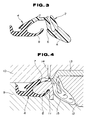
- a part of the window run 4 which is provided with the cut-out 7 is set in forming dies constituted by a lower die 9, an upper die 10, and small middle dies 11, 12, and 13, as appreciated from Fig. 4.
- a molten resin is injected into a cavity 15 through a gate 14 mounted on the upper die 10.
- a sink is formed on the extended part A since the extended part A has a greater thickness as compared with the other parts.
- a weld mark or such like may be caused by the introduction of air due to a swirl stream forming within the cavity 15 during the injection of the molten resin and may appear on an outer surface of the window guide 2.
- an object of the present invention to provide a structure of a window run integrated window guide having a high-finish outer appearance such that no sink, weld marks or jetting appear on the outer surface of an extended portion of a window guide.
- the present invention provides a combined window guide and window run structure applicable to an automotive vehicle comprising a window guide integrally formed with a window run member, said combined structure comprising: a window run member for mounting on a door sash and having an edge portion formed on part of a side wall thereof that faces, in use, the outside of the vehicle body; and a window guide bondingly formed along the edge portion of the window run member and having an obliquely extended portion extending from the contour of the window run member (Structure of the type disclosed e.g. in JP-B-3771/88 or JP-B-47645/88), characterised by the features defined in the characterising portion of claim 1.
- the invention also provides a method of making a combined window guide and window run structure applicable to an automotive vehicle as described above, the method comprising the steps of: preparing a plurality of forming dies comprising a lower die, a top die, and middle small dies with a gate located on the top die, one of the middle small dies being formed with an elongate projection so as to provide a passage of uniform cross-section along the gate; and injecting molten resin through the gate so as to form the window guide, the window guide extending from an edge of the window run member and along the passage of uniform cross-section so that an extended portion of the window guide having a uniform thickness along the elongate projection of the one of the middle small dies is formed without sinks and/or weld marks.
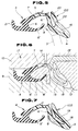
- Figs. 5 and 6 show a first preferred embodiment of a glass guide according to the present invention.
- numeral 4 denotes a window run mounted on a door sash (not shown).
- the window run 4 includes side walls 6, 6' on both inner and outer sides of the vehicle body on a window run substrate 5. Terminals of the side walls 6 at the outer side of the vehicle body are formed with a small-sized window seal lip 8 and engagement lip 20. Terminals of the side wall 6' located on the inner side of the vehicular body are formed with a large-sized glass seal lip 8' and engagement lip 21.
- a part of the window run 4 is provided with an edge portion 7 extending along the base 5 or the window run.
- a glass guide 102 according to the present invention is integrally formed with a resin material at the edge portion 7.
- a window guide 102 is formed substantially along an outer contour of an edge of the window run 4.
- An extended portion A which has a dimension considerably larger than the general dimensions of the window run 4 is installed on the end edge of the window guide 102.
- the extended portion A is contacted with the end of the door window 3 when the door window 3 is raised, thereby permitting the door window 3 to be guided into the window run 4.
- a thickness reducing portion 16 is provided on the extended portion A of the window guide 102 such that the thickness of the extended portion A is the same as that of the other portions of the window guide 102, except the thickness reducing portion .
- numeral 17 denotes the die assembly, including lower die 9, top die 10, middle small dies 11, 12, and 13'.
- Numeral 14 denotes a gate formed on the upper die 10.
- the middle die 13' is formed with a projection 18 on its top end in order to form the thickness reducing portion 16 on the window guide 102.
- the cross section of the cavity 15 within the die assembly 17 becomes uniform.
- a part of the edge portion 7 of the window run 4 is set in the die assembly 17 and in the state described above the molten resin is injected into the cavity 15 through the gate 14.
- the resin smoothly fills corners of the cavity 15 without occurrence of a swirl stream of molten resin, since the cross-section of the passage of the cavity 15 is substantially uniform, i.e., since the extended portion A is not especially thick. Consequently, neither sink nor weld mark occurs on the outer surface of the product.
- Fig. 7 shows a second embodiment of the present invention. Detail similar to that of the first embodiment will be omitted here for brevity.
- the second embodiment is distinguished in that a predetermined number of ribs 19 are formed on a thickness reducing portion 16 of the extended portion A and, thereby, the extended portion A may be reinforced.
- the ribs 19 can easily be formed by forming a predetermined number of grooves along the extended direction of the middle small die 13' shown in Fig. 6.
- the width of the extended portion is defined by limiting portions 22 which define a space through which molten resin may be injected for forming the extended portion.
- a thickness reducing portion 16 is installed on the extended portion to make the thickness of the extended portion thinner with the thickness reducing portion 16 installed on the extended portion and the whole thickness becomes substantially uniform, sinks or weld marks do not appear on the extended portion A after the forming operation.
Landscapes
- Engineering & Computer Science (AREA)
- Mechanical Engineering (AREA)
- Moulds For Moulding Plastics Or The Like (AREA)
- Window Of Vehicle (AREA)
- Seal Device For Vehicle (AREA)
- Vehicle Waterproofing, Decoration, And Sanitation Devices (AREA)
Claims (5)
- Kombinierte Fensterleiteinrichtungs-und-Fensterführungs-Struktur, die bei einem Kraftfahrzeug eingesetzt werden kann und eine als Einheit mit einem Fensterführungselement (4) ausgebildete Fensterleiteinrichtung (102) umfaßt, wobei die kombinierte Struktur umfaßt:
ein Fensterführungselement (4) zur Anbringung an einem Türrahmen mit einem Kantenabschnitt (7), der an einem Teil einer Seitenwand (6) desselben ausgebildet ist, der in Funktion der Außenseite der Fahrzeugkarosserie zugewandt ist; und
eine Fensterleiteinrichtung (102), die damit verbunden an dem Kantenabschnitt (7) des Fensterführungselementes (4) ausgebildet ist und einen schräg verlängerten Abschnitt (A) aufweist, der sich von dem Umriß des Fensterführungselementes (4) aus erstreckt, dadurch gekennzeichnet, daß der verlängerte Abschnitt (A) einen im wesentlichen U-förmigen Querschnitt aufweist, der durch einen Dickenverringerungsabschnitt (16) gebildet wird, so daß die Dicke des verlängerten Abschnitts (A) bis auf den Dickenverringerungsabschnitt (16) im wesentlichen die gleiche ist wie die der restlichen Abschnitte der Fensterleiteinrichtung (102). - Kombinierte Struktur nach Anspruch 1, die des weiteren Dichtungslippen (8, 8') enthält, die an einander gegenüberliegenden Seiten des Fensterführungselements (4) und des verlängerten Abschnitts (A) der Fensterleiteinrichtung (102) ausgebildet sind, wobei ein Zwischenraum zwischen dem Fensterführungselement (4) und der Fensterleiteinrichtung (102) ausgebildet ist, so daß eine Fensterkante zwischen den Dichtungslippen (8, 8') in selbige eingeführt werden kann.
- Kombinierte Struktur nach Anspruch 2, wobei die Fensterführung (102) das Ergebnis der Herstellung mittels Spritzgießen mit einem geschmolzenen Harz ist.
- Kombinierte Struktur nach Anspruch 3, die des weiteren eine vorgegebene Anzahl von Stegen (19) enthält, die an der Innenfläche des U-förmigen verlängerten Abschnitts (A) der Fensterführung (102) ausgebildet ist.
- Verfahren zum Herstellen einer kombinierten Fensterleiteinrichtungs-und-Fensterführungs-Struktur (102), die bei einem Kraftfahrzeug eingesetzt werden kann, nach einem der Ansprüche 1 bis 4, wobei das Verfahren die folgenden Schritte umfaßt:
Herstellen einer Vielzahl von Formen, die eine untere Form (9), eine obere Form (10) und mittlere kleine Formen (11,12,13') umfaßt, wobei sich ein Anschnitt (14) an der oberen Form (10) befindet, wobei eine (13') der mittleren kleinen Formen mit einem länglichen Vorsprung (18) versehen ist, so daß ein Durchlaß mit einheitlichem Querschnitt entlang des Anschnitts (14) gebildet wird; und
Einspritzen von geschmolzenem Harz durch den Anschnitt (14), um so die Fensterleiteinrichtung (102) herzustellen, wobei sich die Fensterleiteinrichtung (102) von einer Kante (7) des Fensterführungselementes (4) aus und entlang des Durchlasses mit einheitlichem Querschnitt erstreckt, so daß ein verlängerter Abschnitt (A) der Fensterleiteinrichtung (102) mit einer einheitlichen Dicke entlang dem länglichen Vorsprung (18) einer der mittleren kleineren Formen (13') ohne Einfallstellen und/oder Schweißstellen hergestellt wird.
Applications Claiming Priority (2)
| Application Number | Priority Date | Filing Date | Title |
|---|---|---|---|
| JP2231208A JP2634934B2 (ja) | 1990-08-31 | 1990-08-31 | グラスラン一体型ガラスガイドの成形方法 |
| JP231208/90 | 1990-08-31 |
Publications (2)
| Publication Number | Publication Date |
|---|---|
| EP0476874A1 EP0476874A1 (de) | 1992-03-25 |
| EP0476874B1 true EP0476874B1 (de) | 1995-10-18 |
Family
ID=16920034
Family Applications (1)
| Application Number | Title | Priority Date | Filing Date |
|---|---|---|---|
| EP91307992A Expired - Lifetime EP0476874B1 (de) | 1990-08-31 | 1991-08-30 | Struktur für Kraftfahrzeugfenster-Führungskanal |
Country Status (5)
| Country | Link |
|---|---|
| US (1) | US5195273A (de) |
| EP (1) | EP0476874B1 (de) |
| JP (1) | JP2634934B2 (de) |
| DE (1) | DE69113942T2 (de) |
| ES (1) | ES2080907T3 (de) |
Families Citing this family (9)
| Publication number | Priority date | Publication date | Assignee | Title |
|---|---|---|---|---|
| US5345718A (en) * | 1993-05-25 | 1994-09-13 | Gencorp Inc. | Glass run guide for slidable vehicle window |
| US5396733A (en) * | 1993-06-09 | 1995-03-14 | Gencorp Inc. | Seal assembly for a movable window for a vehicle |
| GB2350640B (en) * | 1999-06-03 | 2003-11-12 | Draftex Ind Ltd | Sealing or guiding arrangements |
| DE102004050777B4 (de) * | 2004-10-19 | 2021-01-14 | Bayerische Motoren Werke Aktiengesellschaft | Dichtungsanordnung |
| US7762614B2 (en) * | 2006-09-28 | 2010-07-27 | Toyoda Gosei Co., Ltd. | Glass run |
| USD598351S1 (en) * | 2008-07-10 | 2009-08-18 | Creative Extruded Products, Inc. | Molding for sealing a motor vehicle windshield panel with a cowl panel |
| JP5693170B2 (ja) * | 2010-11-18 | 2015-04-01 | 鬼怒川ゴム工業株式会社 | グラスラン |
| CN114347389B (zh) * | 2021-12-31 | 2023-08-11 | 昆山市鸿毅达精密模具有限公司 | 汽车车前门导轨的注塑模具 |
| JP7804519B2 (ja) * | 2022-04-15 | 2026-01-22 | 西川ゴム工業株式会社 | 自動車用ガラスラン |
Family Cites Families (4)
| Publication number | Priority date | Publication date | Assignee | Title |
|---|---|---|---|---|
| JPS6022198Y2 (ja) * | 1980-03-11 | 1985-07-02 | 日産自動車株式会社 | 自動車のガラスランチヤンネル |
| IT8053206U1 (it) * | 1980-05-16 | 1981-11-16 | Fiat Auto Spa | Guarnizione di tenuta per cristallo di porta per autoveicoli |
| JPS584079A (ja) * | 1981-06-26 | 1983-01-11 | 日産自動車株式会社 | ドアガラスの昇降ガイド機構 |
| JPS633771A (ja) * | 1986-06-25 | 1988-01-08 | Iseki Foods Eng Kk | 酢飯処理装置 |
-
1990
- 1990-08-31 JP JP2231208A patent/JP2634934B2/ja not_active Expired - Fee Related
-
1991
- 1991-08-28 US US07/751,145 patent/US5195273A/en not_active Expired - Fee Related
- 1991-08-30 ES ES91307992T patent/ES2080907T3/es not_active Expired - Lifetime
- 1991-08-30 EP EP91307992A patent/EP0476874B1/de not_active Expired - Lifetime
- 1991-08-30 DE DE69113942T patent/DE69113942T2/de not_active Expired - Fee Related
Also Published As
| Publication number | Publication date |
|---|---|
| JPH04110227A (ja) | 1992-04-10 |
| US5195273A (en) | 1993-03-23 |
| DE69113942T2 (de) | 1996-05-15 |
| ES2080907T3 (es) | 1996-02-16 |
| JP2634934B2 (ja) | 1997-07-30 |
| EP0476874A1 (de) | 1992-03-25 |
| DE69113942D1 (de) | 1995-11-23 |
Similar Documents
| Publication | Publication Date | Title |
|---|---|---|
| US7306839B2 (en) | Molded weather strip | |
| US5456049A (en) | Window molding for automobiles | |
| CA2042747C (en) | Door glass run for motor vehicle | |
| US7661953B2 (en) | Process for producing exterior member/seal member assembly | |
| US4986947A (en) | Method for connecting ends of weather strips | |
| EP0586073B1 (de) | Extrudierte Hohlprofile and Herstellungsverfahren | |
| US5195273A (en) | Structure of window run-integrated guide applicable to an automotive vehicle | |
| US5976438A (en) | Method of manufacturing door glass run for motor vehicle | |
| US4663888A (en) | Construction of door glass guide in motor vehicle | |
| JPH07137178A (ja) | 一体成形された中空のトラスを有する樹脂パネル | |
| US5505602A (en) | Mold for producing a weather strip | |
| US20030020301A1 (en) | Automotive weatherstrip and method for molding the same | |
| US20010039763A1 (en) | Window sash | |
| JP3732599B2 (ja) | ドアフレーム | |
| JP3356811B2 (ja) | サッシュレスドア型車のウエザーストリップ | |
| JP3201857B2 (ja) | サッシュレスドア型車のウエザーストリップ取付構造 | |
| GB2071190A (en) | Automotive vehicle door window glass run channel | |
| JP2001239841A (ja) | 自動車ドア用ウエザストリップ | |
| JP4001050B2 (ja) | 自動車用ウエザストリップの製造方法 | |
| JP2674363B2 (ja) | ウエザーストリップの型接続部の成形方法 | |
| JP2632435B2 (ja) | ガラスランのコーナー部成形方法 | |
| JP3036318B2 (ja) | バンパーフェイシアの成形方法 | |
| JPS5818237A (ja) | モ−ルデイングの製造方法 | |
| JP7555885B2 (ja) | グラスランの製造方法 | |
| JPH0664445A (ja) | 自動車用ドアのコーナーピース構造 |
Legal Events
| Date | Code | Title | Description |
|---|---|---|---|
| PUAI | Public reference made under article 153(3) epc to a published international application that has entered the european phase |
Free format text: ORIGINAL CODE: 0009012 |
|
| 17P | Request for examination filed |
Effective date: 19910924 |
|
| AK | Designated contracting states |
Kind code of ref document: A1 Designated state(s): DE ES GB |
|
| 17Q | First examination report despatched |
Effective date: 19931008 |
|
| GRAA | (expected) grant |
Free format text: ORIGINAL CODE: 0009210 |
|
| AK | Designated contracting states |
Kind code of ref document: B1 Designated state(s): DE ES GB |
|
| REF | Corresponds to: |
Ref document number: 69113942 Country of ref document: DE Date of ref document: 19951123 |
|
| REG | Reference to a national code |
Ref country code: ES Ref legal event code: FG2A Ref document number: 2080907 Country of ref document: ES Kind code of ref document: T3 |
|
| PLBE | No opposition filed within time limit |
Free format text: ORIGINAL CODE: 0009261 |
|
| STAA | Information on the status of an ep patent application or granted ep patent |
Free format text: STATUS: NO OPPOSITION FILED WITHIN TIME LIMIT |
|
| 26N | No opposition filed | ||
| PGFP | Annual fee paid to national office [announced via postgrant information from national office to epo] |
Ref country code: DE Payment date: 20000822 Year of fee payment: 10 |
|
| PGFP | Annual fee paid to national office [announced via postgrant information from national office to epo] |
Ref country code: GB Payment date: 20000830 Year of fee payment: 10 Ref country code: ES Payment date: 20000830 Year of fee payment: 10 |
|
| PG25 | Lapsed in a contracting state [announced via postgrant information from national office to epo] |
Ref country code: GB Free format text: LAPSE BECAUSE OF NON-PAYMENT OF DUE FEES Effective date: 20010830 |
|
| PG25 | Lapsed in a contracting state [announced via postgrant information from national office to epo] |
Ref country code: ES Free format text: LAPSE BECAUSE OF NON-PAYMENT OF DUE FEES Effective date: 20010831 |
|
| PG25 | Lapsed in a contracting state [announced via postgrant information from national office to epo] |
Ref country code: DE Free format text: LAPSE BECAUSE OF NON-PAYMENT OF DUE FEES Effective date: 20020501 |
|
| REG | Reference to a national code |
Ref country code: ES Ref legal event code: FD2A Effective date: 20020911 |