EP0477009A1 - Appareil de mesure de la polarisation - Google Patents
Appareil de mesure de la polarisation Download PDFInfo
- Publication number
- EP0477009A1 EP0477009A1 EP91308543A EP91308543A EP0477009A1 EP 0477009 A1 EP0477009 A1 EP 0477009A1 EP 91308543 A EP91308543 A EP 91308543A EP 91308543 A EP91308543 A EP 91308543A EP 0477009 A1 EP0477009 A1 EP 0477009A1
- Authority
- EP
- European Patent Office
- Prior art keywords
- analyzer
- image
- light
- slits
- incident light
- Prior art date
- Legal status (The legal status is an assumption and is not a legal conclusion. Google has not performed a legal analysis and makes no representation as to the accuracy of the status listed.)
- Granted
Links
- 230000010287 polarization Effects 0.000 title claims abstract description 89
- 230000001419 dependent effect Effects 0.000 claims 1
- 238000005259 measurement Methods 0.000 description 31
- 238000001444 catalytic combustion detection Methods 0.000 description 10
- 238000000034 method Methods 0.000 description 9
- 238000004458 analytical method Methods 0.000 description 7
- 230000003287 optical effect Effects 0.000 description 7
- 239000013078 crystal Substances 0.000 description 5
- 238000006073 displacement reaction Methods 0.000 description 4
- 238000010586 diagram Methods 0.000 description 3
- 238000010276 construction Methods 0.000 description 2
- 230000014509 gene expression Effects 0.000 description 2
- 238000010191 image analysis Methods 0.000 description 2
- 230000002123 temporal effect Effects 0.000 description 2
- 230000010354 integration Effects 0.000 description 1
- 238000012986 modification Methods 0.000 description 1
- 230000004048 modification Effects 0.000 description 1
- 230000003595 spectral effect Effects 0.000 description 1
Images


Classifications
-
- G—PHYSICS
- G01—MEASURING; TESTING
- G01J—MEASUREMENT OF INTENSITY, VELOCITY, SPECTRAL CONTENT, POLARISATION, PHASE OR PULSE CHARACTERISTICS OF INFRARED, VISIBLE OR ULTRAVIOLET LIGHT; COLORIMETRY; RADIATION PYROMETRY
- G01J4/00—Measuring polarisation of light
- G01J4/04—Polarimeters using electric detection means
Definitions
- the present invention relates to a polarized light measuring apparatus and a phase plate measuring apparatus, both using Young's interferometer.
- a rotatable polarizer is also provided removably in front of the high speed light detector.
- a temporal waveform of light is first measured without using the polarizer, and again measured with the polarizer attached, and the difference between the two waveforms provides information on the polarization state of the light under measurement.
- those prior apparatuses are disadvantageous in that the polarizer must be movable and actually be moved, and that sufficient information cannot be obtained in the case of circular polarization light and elliptical polarization light. More specifically, the circular polarization cannot be discriminated from the random polarization, and no information can be obtained on the rotational direction of the circular polarization light.
- phase plate measuring apparatus according to Sénarmont's method.
- incident light having horizontal linear polarization is passed through a sample, a quarter-wave plate and finally a polarizer, and output light is observed. Measurements are based on a rotation angle of the polarizer.
- This type of apparatus also suffers from the problem of a necessity of moving the polarizer.
- a polarized light measuring apparatus comprises: Young's interferometer including a single slit, and a double slit member arranged in parallel with said single slit and having two parallel slits which are provided with respective polarizer elements having polarizing directions perpendicular to each other; an analyzer provided downstream of said Young's interferometer; image detecting means for detecting an interference fringe of incident light which has passed through said Young's interferometer and said analyzer; and image analyzing means for producing an intensity profile from an output signal of said image detecting means, and for analyzing said intensity profile to determine a polarization state of said incident light.
- This aspect of the present invention provides a polarized light measuring apparatus which can provide sufficient information on the circular and elliptical polarization light without moving a polarizer.
- a phase plate measuring apparatus comprises: light source means for emitting incident light having known polarization; Young's interferometer including a single slit, and a double slit member arranged in parallel with said single slit and having two parallel slits which are provided with respective polarizer elements having polarizing directions perpendicular to each other; a phase plate disposed between said light source means and said Young,s interferometer; means for rotating said phase plate about an axis of said incident light; means for detecting a rotation angle of said phase plate; image detecting means for detecting an interference fringe of said incident light which has passed through said phase plate, said Young's interferometer and said analyzer; and image analyzing means for producing an intensity profile from an output signal of said image detecting means, and for determining a phase difference and an axis of said phase plate on the basis of said detected rotation angle and a corresponding shift of a peak of said intensity profile.
- This second aspect of the invention provides a phase plate measuring apparatus which can perform desired measurements without rotating a polarizer.
- the polarization state of incident light can be determined without any movable part. Circular polarization and random polarization can be discriminated from each other, and the rotational direction of circularly polarized light can be obtained.
- a high speed variation of polarization state can be measured with high precision.
- a variation of wavelength (chirp) can be measured.
- the axis and the retardation of the phase plate can be determined quickly.
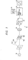
- a polarized light measuring apparatus 10 Young's interferometer 18 including a single slit 14 and double slits 16 parallel to the single slit, an analyzer 20 and an image detector unit 22 are disposed, in this order, on the optical axis of light emitted from a light source 12 under measurement.
- the polarized light measuring apparatus 10 further includes an image analyzer unit 24 for analyzing a detected image on the basis of an output signal of the image detector unit 22, and a polarization state output unit 26 for displaying results of the analysis of the image analyzer unit 24.
- the analyzer 20 is arranged such that its polarizing direction becomes parallel to the longitudinal direction of each of the slits 14 and 16. Therefore, the polarizing direction of the analyzer 20 is deviated by + 45° and - 45° from those of the polarizers 16A and 16B, respectively.
- the image detector unit 22 acts as a two-dimensional sensor, and detects interference fringes.
- the image analyzer unit 24 produces an intensity distribution, i.e., "profile" of the interference fringe based on an output pattern in the form of alternate bright and dark bands of the image detector unit 22.
- the polarization state of the light emitted from the light source 12 is detected by analyzing the profile of the detected interference fringe.
- the profile output unit 25 displays the profile thus obtained as an intermediate output of the image analyzer unit 24.
- the polarization state output unit 26 outputs results of the analysis by the image analyzer unit 24.
- the image analyzer unit 24 will be described in more detail. All the conceivable profiles of the interference fringes which would be obtained in response to various polarization states of incident light are stored in advance in the analyzer unit 24. The analyzer unit 24 sequentially compares, with the stored profiles, the profile which has been produced based on the interference fringe from the detector unit 22, and picks up one of the stored profiles which most closely resembles the produced profile to determine the polarization state. The result is provided to the polarization state output unit 26.
- Figs. 2 and 3 The relationships between the polarization states of incident light and the profiles produced by the image analyzer unit 24 are as shown in Figs. 2 and 3.
- the profiles are shown in the right columns of these figures, in which the ordinate represents brightness (i.e., intensity), and the abscissa, a position.
- the polarization state output unit 26 displays, for instance, the fact of linear polarization and its angle as shown in parts (A)-(H) of Fig. 2, left column, or the fact of circular polarization and its rotational direction, i.e., dextrorotation or levorotation as shown in parts (I)-(J) of Fig. 2, left column.
- Fig. 3 illustrates only the dextrorotatory elliptical polarizations.
- the angle and ellipticity of a resulting elliptical polarization can be determined by analysis based on the phase and envelope of the original profile which are stored in advance in the image analyzer unit 2 4.
- the light emitted from the light source 12 passes through the single slit 14, double slits 16 and analyzer 20, and forms an interference fringe on the image detector unit 22.
- the image analyzer unit 24 compares the profile of this interference fringe with the profiles stored therein, and picks up one of the stored profiles which most closely resembles the produced profile.
- the analyzer unit 24 determines the polarization state of the incident light on the basis of the profile thus picked up, and provides the polarization state output unit 26 with the results, that is, the fact of linear polarization and its angle, the fact of circular polarization and its rotational direction, or the fact of elliptical polarization and its angle and ellipticity.
- the polarization state output unit 26 displays such results of analysis.
- all the conceivable profiles are stored in advance in the image analyzer unit 24, and the analyzer unit 24 selects one of the profiles which most closely resembles the profile of an interference fringe detected by the image detector unit 22, and determines the polarization state of incident light from the profile thus selected.
- This procedure may be called "complete matching system”.
- the present invention is not limited to the complete matching system, but may be based on a "partial matching system”.
- the kind of polarization state i.e., linear, circular or elliptical polarization, is judged from the center state of the profile produced in the image analyzer unit 24.
- linear polarization in the case of linear polarization (except for the angles of ⁇ 45°), a peak or valley of a profile is located at its center, and in circular or elliptical polarization, a ridge line of a profile crosses its center line. Therefore, linear polarization may be distinguished from circular or elliptical polarization.
- the polarization direction of a linear polarization can be determined based on the difference between the intensities of a profile on the right and left sides of its center and whether a peak or valley is located at the center.
- the dextrorotatory and levorotatory circular polarizations can be discriminated from each other based on whether the left-side ridge line (part (I) of Fig. 2) or the right-side ridge line (part (J)) crosses the center line.
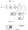
- the second embodiment employs a streak camera 28 as a high speed version of the image detector unit 22 of the first embodiment.
- the streak camera 28 and an incidence-side slit 28A disposed in front of the streak camera 28 make up a high speed line sensor.
- An image analyzer unit 30 judges the polarization state of light emitted from a light source 12 under measurement on the basis of a streak image obtained by the streak camera 28.
- the streak image is displayed on a streak-image output unit 27.
- the intervals of an interference fringe of a streak image indicate a wavelength of the incident light; the modulation degree, a wavelength spread; the phase and envelope, polarization states; and the width along the time axis, a pulse width of the incident light.
- Fig. 5 shows an example of a streak image of an interference fringe. Since the intervals of an interference fringe depends on the wavelength of incident light, narrowing of intervals of the interference fringe from position A to position B in Fig. 5 indicates a wavelength shift to the shorter wavelength side.
- the phase of an interference fringe depends on the polarization states.
- the valley of the interference fringe lies at its center. This indicates the horizontal linear polarization.
- the pulse width of the incident light can be determined from the width of the streak image in the time axis direction.
- the polarization states may be evaluated by sequentially analyzing the interference fringes of respective time points; in other words, there is no need of analyzing the whole streak image at one time.
- a window having a sufficiently small time width on the time axis of the streak image is set in the direction of the incidence-side slit 28A.
- a profile of the streak image obtained is picked up by the image analyzer unit 30.
- the profile thus obtained is the same as the first embodiment. Therefore, if conceivable profiles are stored in the image analyzer unit 30, the polarization state of the light under measurement at that moment can be determined according to the complete matching system or partial matching system.
- the apparatus of the second embodiment can concurrently perform not only the polarization state of light under measurement but also time-resolving measurements such as a high speed variation of polarization, a pulse width of light, a wavelength shift (chirp), a variation of a wavelength spread.
- the analyzer 20 is fixed at 0° in the first and second embodiments described above, the invention is not limited to such a case but the analyzer 20 may be arranged in a rotatable manner.
- an arrangement of a third embodiment as shown in Fig. 6 may be used.
- the intensities of the light beams which emanate from the double slits 16 and travel toward the input plane of the image detector unit 22 can be controlled to be equal to each other by rotating the analyzer 20.
- This arrangement facilitates the measurement of interference fringes, and consequently provides easy and accurate analysis of polarization states.
- reference numeral 20A designates a holder for the analyzer 20; 20B, an actuator for rotating the analyzer 20 together with the holder 20A; and 22A, an image input plane of the image detector unit 22.
- the light under measurement is a linearly polarized light having a polarization direction at 60° from the vertical direction.
- intensities of the light beams extracted by the polarizers 16A and 16B of the double slits 16 are 0.933 for the direction of + 45° and 0.067 for the direction of - 45°. Since the difference between these two intensities is too large, it is difficult to obtain the ratio of the two intensities from the profile produced by the image analyzer unit 24 (see Fig. 7(B)).
- the analyzer 20 may be rotated by an appropriate amount about the optical axis to cancel out the above difference in light intensity.
- a rotation angle with respect to the vertical direction is represented as X degree
- the + 45° component of the light incident on the image detector unit 22 is 0.933cos2(X - 45°) and the - 45° component is 0.067sin2(X -45°).
- the angle X to equalize the two components is 120°. Therefore, if the analyzer 20 is rotated about the optical axis by 120°, the envelope of the profile formed by the image analyzer unit 24 becomes symmetrical, facilitating the measurement.
- A2cos2(X -45°) B2sin2 (X - 45°).
- the analyzer 20 is rotated so that the average intensity of the envelope of the profile that is formed by the image analyzer unit 24 becomes symmetrical with respect to the vertical center line, and the rotation angle of the analyzer 20 is measured.
- the ratio of the components of the light beams extracted by the polarizers 16Aand 16B is obtained on the basis of the measured rotation angle. To obtain this ratio, a signal representing an operation amount of the actuator 20B is provided to the image analyzer unit 24.
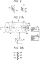
- an analyzer 32 having first to third analyzer elements 32A-32C is disposed between the double slits 16 and the image detector unit 22 such that the analyzer elements 32A-32C are arranged in the longitudinal direction of the double slits 16.
- the polarizing directions of the first and second analyzer elements 32A and 32B coincide with those of the polarizers 16A and 16B of the double slits, respectively.
- the polarizing direction of the third analyzer element 32C, disposed between the first and second analyzer elements 32A and 32B, coincides with the longitudinal direction (i.e., vertical direction in Fig. 8) of the double slits 16.
- the image detector unit 22 consists of three one-dimensional CCDs 34A-34C arranged in association with the respective analyzer elements 32A-32C.
- An optical measuring head 36 is made up of a single slit 14, double slits 16, the analyzer 32 and the one dimensional CCDs 34A-34C which are arranged such that their axis is the same as the optical axis of the light emitted from the light source 12 under measurement.
- the single slit 14, double slits 16, analyzer 32 and one-dimensional CCDs 34A-34C are arranged in this order within a lens-barrel 38 whose inside surface is painted black.
- the optical measuring head 36 is positioned using a magnetic stand 40 so that its axis becomes coincident with the axis of the light under measurement.
- the positional relationship among the single slit 14, double slits 16 and analyzer 32 will be described below in detail.
- P represent a reference line which is drawn through the center of the single slit 14 and is perpendicular to the longitudinal direction of the single slit 14.
- P′ represent another reference line which is drawn through the center of the double slits 16 and is perpendicular to the longitudinal direction of the double slits 16.
- the third analyzer element 32C is disposed on a line P ⁇ where the plane defined by the reference lines P and P′ intersect the plane of the analyzer 32, in such a manner that its polarizing direction is perpendicular to the line P ⁇ .
- the first and second analyzer elements 32A and 32B are disposed such that these sandwich the third analyzer element 32C in the direction perpendicular to the line P ⁇ , and that they are equidistantly separated from the reference line P ⁇ .
- the one-dimensional CCDs 34A to 34C are disposed in close contact with the rear faces of the first to third analyzer elements 32A-32C, respectively.
- each of the one-dimensional CCDs 34A-34C has 1024 pixels
- profiles output from the CCDs 34A and 34B corresponding to the first and second analyzer elements 32A and 32B will be as shown in Figs. 10(A) and 10(B), respectively.
- the center line is drawn to identify an output signal of the 512th element as the central element of each CCD.
- a profile obtained from the output of the third analyzer element 32C is as shown in Fig. 10(C), and has an envelope of an interference fringe, which depends on the profiles of Figs. 10(A) and 10(C).
- reference letter D indicates the difference between the element numbers of the two elements producing the peak values which are closest to the central element represented by the element number 512.
- Reference letter D indicates the difference between the element number of the element producing the peak value closest to and on the right side of the central element and the central element number 512.
- Integration values A and B of output signals 1 1 and W2 of the one-dimensional CCDs 34A and 34B shown in Figs. 10(A) and 10(B) are respectively expressed as: W1(N), and W2(N).
- A/B represents a ratio between intensities of the light components extracted by the polarizers 16A and 16B.
- arbitrary polarization state of light under measurement can be determined on the basis of the ratio A/B and the angle ⁇ .
- the central wavelength of the light under measurement can be obtained from the value D.
- the value D may be any of the difference between the element numbers of the elements corresponding to the two valleys located closest to the central element, an average of intervals between adjacent peaks over the entire profile, and an average of intervals between adjacent valleys over the entire profile.
- I(x) I1(x) + I2(x) + 2 I1(x)I2(x) cos (Kx + ⁇ )
- x position on the input surface
- I1 (X) and I2(X) profiles obtained when light beams passed through the respective slits of the double slits 16 are observed without subjected to interference
- K proportional constant depending on the layout of the optical system and the wavelength
- ⁇ phase of an interference fringe.
- equation (1) contains the terms of I1(x) and I2(x)
- the method based on the peaks of a profile will possibly create an error in the phase value ⁇ obtained where the profile I1(X) or I2(X) sharply varies.
- the phase ⁇ is precisely calculated from equation (2).
- a corrected output signal W3′(N) [W3(N) - ⁇ W1(N) + W2(N) ⁇ ]/2 W1(N)W2(N) .
- the above procedure of calculating the phase of the profile of an interference fringe can likewise be applied to the case of a light source having a certain spectral spread, to calculate the phase in a precise manner.
- the polarization state can be obtained on the basis of the ratio A/B and the phase ⁇
- the wavelength spread of the light under measurement can be determined from a profile spread at the peak of the corrected output signal W3′(N).
- first to third analyzer elements 32A-32C of the analyzer 32 are vertically arranged.
- first to third analyzer elements 42A to 42C which are similar to the analyzer elements 32A-32C, may be arranged horizontally, i.e., in the width direction of the double slits 16, as shown in Fig. 11(A).
- a single one-dimensional sensor 44 may be used for the image detector unit as shown in Fig. 11(B).
- Fig. 11(C) shows an example of a profile obtained from light which is passed through the first to third analyzer elements 42A-42C and detected by the sensor 44. Part C′ of the profile, which results from the interference, is obtained in association with the third analyzer element 42C. Only the intensity information is obtained in association with the first and second analyzer elements 42A and 42B, as shown in Fig. 11(C) as parts A′ and B′.
- the width of the third analyzer element 42C is limited, the number of bands in an interference fringe is small. But the small number causes no problem because it suffices that the phase difference of polarized light is determined from the position of the profile peak.
- parts A′ and B′ which correspond to the first and second analyzer elements 42A and 42B have no bands, the ratio between the intensities of the light beams after passing through the two slits of the double slits 16 may readily be obtained.
- the slit width and the distance between the slits of the double slits 16 are fixed, but the invention is not limited to this type.
- double slits 17 may be driven by an actuator 19 to vary the distance between the slits.
- polarizers 17A and 17B having the same polarizing directions as the polarizers 16A and 16B, respectively, are elongated in the movement direction over the movable range of the double slits 17.
- an interference fringe suitable for the wavelength of the light under measurement can be obtained by selecting an appropriate distance between the slits of the double slits 17.
- a plurality of double slits 48A-48C having different intervals may be arranged in a single plate 46, and incident light may be passed through the double slit 48A-48C simultaneously.
- Additional double slits 48D may also be provided which have a slit width and interval that will cause no interference, and the incident light may also be passed through the double slits 48D simultaneously.
- All of the above double slits are provided with polarizers having orthogonal polarizing directions, as in the first embodiment.
- the number of bands in an interference fringe of a profile produced by the image analyzer unit 24 becomes small, which makes the image analysis difficult.
- the polarization state of incident light is determined by comparison of the phase and envelope of a profile that results from the passage through the polarizers 16A and 16B with those of the stored profiles.
- the envelope becomes unclear accordingly and the measurement accuracy will be degraded.
- a clear interference fringe which means that the associated double slits are suitable for the wavelength of the incident light, may be selected among the interference fringes formed by the respective double slits 48A-48C (see Fig. 14), for subsequent image analysis and measurement.
- the phase of a profile can be determined with high precision.
- the incident light beams extracted by the polarizers 16A and 16B and passed through the analyzer 20 represent their own intensities.
- the ratio between intensities of the two light beams can easily be determined. Therefore, according to the sixth embodiment, the phase and intensity ratio of a profile can be obtained precisely, and a highly accurate measurement of the polarization state of the incident light can be performed.
- the sixth embodiment requires a two-dimensional sensor as the image detector unit, since the images of the incident light beams passing through the double slits 48A-48D in the plate 46 should be detected simultaneously.
- the polarization state of light under measurement is determined by, for instance, the pattern matching which is performed in the analyzer unit 24 or 30 such that the profile produced from the output of the image detector unit 22 or streak camera 28 is compared with the stored profiles.
- Fig. 15 shows a seventh embodiment of the invention, in which the polarization state of incident light is determined in an image analyzer unit 49 by a Fourier transform method.
- the polarization state of light under measurement can be determined if the intensity ratio A/B of and the phase difference ⁇ between the light beams passing through the polarizers 16A and 16B of the double slits 16 and the analyzer 20 or 32.
- Fourier transform is applied to the profile to produce a frequency-axis profile.
- an interference fringe component high frequency component
- the other component low frequency component
- F ⁇ I A (X) ⁇ and F ⁇ I B (X) ⁇ can be obtained by Fourier-transforming the profile I(x) of Fig. 16(B).
- "F” is a Fourier transform operator.
- F ⁇ I A (X) ⁇ and F ⁇ I B (X) ⁇ can be separated on the frequency axis.
- I A (X) of Fig. 16(C) can be obtained by removing F ⁇ I B (X) ⁇ in Fig. 17(A) using a low-pass filter, and then inverse-Fourier-transforming the filtered result.
- a and B can be calculated from the above two equations and the data of I A (x) of Fig. 16(C).
- a and B represent the intensity amplitudes of I A (X) and I B (X), respectively; 2d, the distance between the slits of the double slits 16; and K′, a proportional constant.
- I B (X) of Fig. 16(D) can be obtained by removing F ⁇ I A (X) ⁇ in Fig. 17(A) using a high-pass filter, and inverse-Fourier-transforming the filtered result.
- phase difference ⁇ 360° ⁇ T2 /T1.
- phase difference ⁇ can directly be calculated from the ratio between the real part and the imaginary part of Fourier-transformed data F ⁇ I B (x) ⁇ .
- respective component profiles can be separated by Fourier-transforming the profile of an interference fringe which is formed by superposition of a plurality of (e.g., two) fringes of wavelengths ⁇ 1 and ⁇ 2 (see Fig. 18(B)).
- the Fourier-transform-based technique of the seventh embodiment can also be applied to the second embodiment using the streak camera 28 to perform time-resolving measurements.
- an image as shown in Fig. 19(B) is formed by Fourier-transforming a time-resolved interference fringe of Fig. 19(A) only in the x-axis.
- a time waveform of the light under measurement can be obtained from the interference fringe of Fig. 19(A).
- the image of Fig. 19(B) provides a temporal variation of wavelength, i.e., a chirp, and a variation of the phase difference between light beams which have passed through the double slits 16.
- the eighth embodiment relates to an apparatus for measuring orientation of the crystal axis and the phase difference of a phase plate.
- Incident light is linearly polarized light.
- a phase plate 50 to be measured is disposed on the incidence side of Young's interferometer 18, in which two polarizers having orthogonal polarizing directions are provided in respective slits of double slits, in such a manner as to be rotatable about the axis of the incident light by means of a motor 52.
- An encoder 58 for measuring a rotation angle of the phase plate 50 is also used.
- An image signal obtained by the image detector unit 22 is analyzed by an image analyzer unit 24.
- a profile output unit 25 displays an obtained profile as an intermediate output of the image analyzer unit 24.
- a computing unit 56 determines the orientation of the crystal axis and the phase difference of the phase plate 50 based on the analysis results of an interference fringe, and have a display unit 60 display those results.
- the remaining arrangement of the eighth embodiment is substantially the same as that of the Fig. 1 embodiment.
- the linearly polarized light is passed through the phase plate 50, which is rotated by the motor 52, and then detected by the image detector unit 22.
- the peak of a profile of an interference fringe oscillates with the line "O" (screen center) in Fig. 20 as a central axis in accordance with the phase difference of the phase plate 50.
- phase difference of the phase plate 50 can be determined on the basis of the maximum angle of ⁇ .
- a position at which the peak of the profile is located at the central axis O represents the crystal axis or the axis perpendicular thereto, i.e., the phase retardation axis or advancement axis of the crystal constituting the phase plate 50.
- the phase difference and the axis can be obtained in the following manner.
- the motor is rotated via the computing unit 56 so that a maximum peak displacement of the profile, which is obtained by the image analyzer unit 24, is obtained.
- the output data of the encoder at that time indicates the phase difference and the axis.
- the present invention is not limited to such a case, but may be applied to incident light having any type of polarization if it is known.
Landscapes
- Physics & Mathematics (AREA)
- General Physics & Mathematics (AREA)
- Spectroscopy & Molecular Physics (AREA)
- Length Measuring Devices By Optical Means (AREA)
- Investigating Or Analysing Materials By Optical Means (AREA)
- Instruments For Measurement Of Length By Optical Means (AREA)
Applications Claiming Priority (2)
| Application Number | Priority Date | Filing Date | Title |
|---|---|---|---|
| JP251317/90 | 1990-09-20 | ||
| JP02251317A JP3095231B2 (ja) | 1990-09-20 | 1990-09-20 | 偏光測定装置及び位相板測定装置 |
Publications (2)
| Publication Number | Publication Date |
|---|---|
| EP0477009A1 true EP0477009A1 (fr) | 1992-03-25 |
| EP0477009B1 EP0477009B1 (fr) | 1994-12-14 |
Family
ID=17221014
Family Applications (1)
| Application Number | Title | Priority Date | Filing Date |
|---|---|---|---|
| EP91308543A Expired - Lifetime EP0477009B1 (fr) | 1990-09-20 | 1991-09-19 | Appareil de mesure de la polarisation |
Country Status (4)
| Country | Link |
|---|---|
| US (1) | US5237388A (fr) |
| EP (1) | EP0477009B1 (fr) |
| JP (1) | JP3095231B2 (fr) |
| DE (1) | DE69105893T2 (fr) |
Cited By (1)
| Publication number | Priority date | Publication date | Assignee | Title |
|---|---|---|---|---|
| WO1993006445A1 (fr) * | 1991-09-19 | 1993-04-01 | Allied-Signal Inc. | Systeme analyseur de signal spectral |
Families Citing this family (7)
| Publication number | Priority date | Publication date | Assignee | Title |
|---|---|---|---|---|
| US6765681B1 (en) * | 2001-04-10 | 2004-07-20 | Intel Corporation | Measuring optical phase |
| DE10236422A1 (de) * | 2002-08-08 | 2004-02-26 | Infineon Technologies Ag | Verfahren zur Charakterisierung einer Beleuchtungsquelle in einem Belichtungsgerät |
| US7456962B2 (en) * | 2005-02-07 | 2008-11-25 | Meadowlark Optics, Inc. | Conical refraction polarimeter |
| US7289689B2 (en) * | 2005-08-24 | 2007-10-30 | Massachusetts Institute Of Technology | Combinatorial polarization scramblers for many segment PMD emulator |
| JP2007180152A (ja) * | 2005-12-27 | 2007-07-12 | Canon Inc | 測定方法及び装置、露光装置、並びに、デバイス製造方法 |
| US7777879B2 (en) * | 2007-02-01 | 2010-08-17 | Stmicroelectronics (Research & Development) Ltd. | Rotary encoders |
| CN101846553B (zh) * | 2010-03-30 | 2011-09-07 | 北京理工大学 | 一种利用双缝干涉法测量偏振态的方法 |
Citations (2)
| Publication number | Priority date | Publication date | Assignee | Title |
|---|---|---|---|---|
| GB1212946A (en) * | 1967-08-31 | 1970-11-18 | Centre Nat Rech Scient | Polarimeter |
| US4310247A (en) * | 1979-04-21 | 1982-01-12 | International Business Machines Corporation | Method and apparatus for analyzing the state of polarization of radiation |
Family Cites Families (1)
| Publication number | Priority date | Publication date | Assignee | Title |
|---|---|---|---|---|
| US3700334A (en) * | 1970-11-13 | 1972-10-24 | Nasa | Interferometer-polarimeter |
-
1990
- 1990-09-20 JP JP02251317A patent/JP3095231B2/ja not_active Expired - Fee Related
-
1991
- 1991-09-19 EP EP91308543A patent/EP0477009B1/fr not_active Expired - Lifetime
- 1991-09-19 US US07/762,457 patent/US5237388A/en not_active Expired - Lifetime
- 1991-09-19 DE DE69105893T patent/DE69105893T2/de not_active Expired - Fee Related
Patent Citations (2)
| Publication number | Priority date | Publication date | Assignee | Title |
|---|---|---|---|---|
| GB1212946A (en) * | 1967-08-31 | 1970-11-18 | Centre Nat Rech Scient | Polarimeter |
| US4310247A (en) * | 1979-04-21 | 1982-01-12 | International Business Machines Corporation | Method and apparatus for analyzing the state of polarization of radiation |
Non-Patent Citations (1)
| Title |
|---|
| APPLIED OPTICS, vol. 29, no. 2, January 10, 1990, S.NAKADATE "High precision retardation measurement using phase detection of Young's fringes", pages 242-246 * |
Cited By (1)
| Publication number | Priority date | Publication date | Assignee | Title |
|---|---|---|---|---|
| WO1993006445A1 (fr) * | 1991-09-19 | 1993-04-01 | Allied-Signal Inc. | Systeme analyseur de signal spectral |
Also Published As
| Publication number | Publication date |
|---|---|
| DE69105893T2 (de) | 1995-07-13 |
| JPH04130234A (ja) | 1992-05-01 |
| EP0477009B1 (fr) | 1994-12-14 |
| DE69105893D1 (de) | 1995-01-26 |
| JP3095231B2 (ja) | 2000-10-03 |
| US5237388A (en) | 1993-08-17 |
Similar Documents
| Publication | Publication Date | Title |
|---|---|---|
| US6052188A (en) | Spectroscopic ellipsometer | |
| DE69524298T2 (de) | Apparat und Verfahren zum Messen einer Verschiebung | |
| DE69722876T2 (de) | Vorrichtung und Verfahren zur optischen Profilmessung | |
| US7286226B2 (en) | Method and apparatus for measuring birefringence | |
| JP7716977B2 (ja) | スナップショットエリプソメータ | |
| EP0561015A1 (fr) | Mesure de phase interferométrique | |
| US6137575A (en) | Film thickness measuring method and apparatus | |
| US20010024277A1 (en) | Method of evaluating an anisotropic thin film and an evaluating apparatus | |
| EP0477009B1 (fr) | Appareil de mesure de la polarisation | |
| US5600440A (en) | Liquid crystal interferometer | |
| CA2122782C (fr) | Appareil et methode pour mesurer un parametre physique dans une fibre de detection tres birefringente | |
| Jackson | Analysis of variable-density seismograms by means of optical diffraction | |
| Zhang et al. | Tempo-spatially modulated imaging spectropolarimetry based on polarization modulation array | |
| US6373569B1 (en) | Method and device for the spectral analysis of light | |
| KR101373709B1 (ko) | 3차원 필름의 주축과 위상차의 측정장치 및 측정방법 | |
| US4345838A (en) | Apparatus for spectrometer alignment | |
| EP1598647A1 (fr) | Interféromètre et spectromètre de transformée de Fourier | |
| JP3436704B2 (ja) | 複屈折測定方法及びその装置 | |
| JPH05264220A (ja) | 距離測定のための光学的方法と光学装置、および部品の相対的位置決めへのその応用 | |
| US6646743B2 (en) | Method and device for the spectral analysis of light | |
| DE4242883C2 (de) | Verfahren zur 3-D-Shear-Bildauswertung | |
| JP2997299B2 (ja) | 複屈折測定方法 | |
| JPH05281137A (ja) | 複屈折測定装置 | |
| EP0179151A1 (fr) | Signal d'echantillonnage pour la production d'interferogramme et son procede d'obtention | |
| Joseph Gottlieb | Design and construction of an optimal Mueller matrix imaging polarimeter for biomedical applications |
Legal Events
| Date | Code | Title | Description |
|---|---|---|---|
| PUAI | Public reference made under article 153(3) epc to a published international application that has entered the european phase |
Free format text: ORIGINAL CODE: 0009012 |
|
| AK | Designated contracting states |
Kind code of ref document: A1 Designated state(s): DE FR GB |
|
| 17P | Request for examination filed |
Effective date: 19920924 |
|
| 17Q | First examination report despatched |
Effective date: 19931116 |
|
| GRAA | (expected) grant |
Free format text: ORIGINAL CODE: 0009210 |
|
| AK | Designated contracting states |
Kind code of ref document: B1 Designated state(s): DE FR GB |
|
| REF | Corresponds to: |
Ref document number: 69105893 Country of ref document: DE Date of ref document: 19950126 |
|
| ET | Fr: translation filed | ||
| PLBE | No opposition filed within time limit |
Free format text: ORIGINAL CODE: 0009261 |
|
| STAA | Information on the status of an ep patent application or granted ep patent |
Free format text: STATUS: NO OPPOSITION FILED WITHIN TIME LIMIT |
|
| 26N | No opposition filed | ||
| PGFP | Annual fee paid to national office [announced via postgrant information from national office to epo] |
Ref country code: DE Payment date: 20000911 Year of fee payment: 10 |
|
| REG | Reference to a national code |
Ref country code: GB Ref legal event code: IF02 |
|
| PG25 | Lapsed in a contracting state [announced via postgrant information from national office to epo] |
Ref country code: DE Free format text: LAPSE BECAUSE OF NON-PAYMENT OF DUE FEES Effective date: 20020501 |
|
| PGFP | Annual fee paid to national office [announced via postgrant information from national office to epo] |
Ref country code: FR Payment date: 20050823 Year of fee payment: 15 |
|
| PGFP | Annual fee paid to national office [announced via postgrant information from national office to epo] |
Ref country code: GB Payment date: 20050914 Year of fee payment: 15 |
|
| GBPC | Gb: european patent ceased through non-payment of renewal fee |
Effective date: 20060919 |
|
| REG | Reference to a national code |
Ref country code: FR Ref legal event code: ST Effective date: 20070531 |
|
| PG25 | Lapsed in a contracting state [announced via postgrant information from national office to epo] |
Ref country code: GB Free format text: LAPSE BECAUSE OF NON-PAYMENT OF DUE FEES Effective date: 20060919 |
|
| PG25 | Lapsed in a contracting state [announced via postgrant information from national office to epo] |
Ref country code: FR Free format text: LAPSE BECAUSE OF NON-PAYMENT OF DUE FEES Effective date: 20061002 |