EP0877168A1 - Dispositif d'entrainement hydraulique - Google Patents
Dispositif d'entrainement hydraulique Download PDFInfo
- Publication number
- EP0877168A1 EP0877168A1 EP97912461A EP97912461A EP0877168A1 EP 0877168 A1 EP0877168 A1 EP 0877168A1 EP 97912461 A EP97912461 A EP 97912461A EP 97912461 A EP97912461 A EP 97912461A EP 0877168 A1 EP0877168 A1 EP 0877168A1
- Authority
- EP
- European Patent Office
- Prior art keywords
- pressure
- setting
- differential pressure
- valve
- rotational speed
- Prior art date
- Legal status (The legal status is an assumption and is not a legal conclusion. Google has not performed a legal analysis and makes no representation as to the accuracy of the status listed.)
- Granted
Links
Images


Classifications
-
- F—MECHANICAL ENGINEERING; LIGHTING; HEATING; WEAPONS; BLASTING
- F15—FLUID-PRESSURE ACTUATORS; HYDRAULICS OR PNEUMATICS IN GENERAL
- F15B—SYSTEMS ACTING BY MEANS OF FLUIDS IN GENERAL; FLUID-PRESSURE ACTUATORS, e.g. SERVOMOTORS; DETAILS OF FLUID-PRESSURE SYSTEMS, NOT OTHERWISE PROVIDED FOR
- F15B11/00—Servomotor systems without provision for follow-up action; Circuits therefor
- F15B11/02—Systems essentially incorporating special features for controlling the speed or actuating force of an output member
- F15B11/04—Systems essentially incorporating special features for controlling the speed or actuating force of an output member for controlling the speed
- F15B11/05—Systems essentially incorporating special features for controlling the speed or actuating force of an output member for controlling the speed specially adapted to maintain constant speed, e.g. pressure-compensated, load-responsive
-
- E—FIXED CONSTRUCTIONS
- E02—HYDRAULIC ENGINEERING; FOUNDATIONS; SOIL SHIFTING
- E02F—DREDGING; SOIL-SHIFTING
- E02F9/00—Component parts of dredgers or soil-shifting machines, not restricted to one of the kinds covered by groups E02F3/00 - E02F7/00
- E02F9/20—Drives; Control devices
- E02F9/22—Hydraulic or pneumatic drives
- E02F9/2221—Control of flow rate; Load sensing arrangements
- E02F9/2232—Control of flow rate; Load sensing arrangements using one or more variable displacement pumps
-
- E—FIXED CONSTRUCTIONS
- E02—HYDRAULIC ENGINEERING; FOUNDATIONS; SOIL SHIFTING
- E02F—DREDGING; SOIL-SHIFTING
- E02F9/00—Component parts of dredgers or soil-shifting machines, not restricted to one of the kinds covered by groups E02F3/00 - E02F7/00
- E02F9/20—Drives; Control devices
- E02F9/22—Hydraulic or pneumatic drives
- E02F9/2278—Hydraulic circuits
- E02F9/2285—Pilot-operated systems
-
- E—FIXED CONSTRUCTIONS
- E02—HYDRAULIC ENGINEERING; FOUNDATIONS; SOIL SHIFTING
- E02F—DREDGING; SOIL-SHIFTING
- E02F9/00—Component parts of dredgers or soil-shifting machines, not restricted to one of the kinds covered by groups E02F3/00 - E02F7/00
- E02F9/20—Drives; Control devices
- E02F9/22—Hydraulic or pneumatic drives
- E02F9/2278—Hydraulic circuits
- E02F9/2296—Systems with a variable displacement pump
-
- F—MECHANICAL ENGINEERING; LIGHTING; HEATING; WEAPONS; BLASTING
- F04—POSITIVE - DISPLACEMENT MACHINES FOR LIQUIDS; PUMPS FOR LIQUIDS OR ELASTIC FLUIDS
- F04B—POSITIVE-DISPLACEMENT MACHINES FOR LIQUIDS; PUMPS
- F04B49/00—Control, e.g. of pump delivery, or pump pressure of, or safety measures for, machines, pumps, or pumping installations, not otherwise provided for, or of interest apart from, groups F04B1/00 - F04B47/00
- F04B49/08—Regulating by delivery pressure
-
- F—MECHANICAL ENGINEERING; LIGHTING; HEATING; WEAPONS; BLASTING
- F04—POSITIVE - DISPLACEMENT MACHINES FOR LIQUIDS; PUMPS FOR LIQUIDS OR ELASTIC FLUIDS
- F04B—POSITIVE-DISPLACEMENT MACHINES FOR LIQUIDS; PUMPS
- F04B49/00—Control, e.g. of pump delivery, or pump pressure of, or safety measures for, machines, pumps, or pumping installations, not otherwise provided for, or of interest apart from, groups F04B1/00 - F04B47/00
- F04B49/22—Control, e.g. of pump delivery, or pump pressure of, or safety measures for, machines, pumps, or pumping installations, not otherwise provided for, or of interest apart from, groups F04B1/00 - F04B47/00 by means of valves
- F04B49/24—Bypassing
-
- F—MECHANICAL ENGINEERING; LIGHTING; HEATING; WEAPONS; BLASTING
- F04—POSITIVE - DISPLACEMENT MACHINES FOR LIQUIDS; PUMPS FOR LIQUIDS OR ELASTIC FLUIDS
- F04B—POSITIVE-DISPLACEMENT MACHINES FOR LIQUIDS; PUMPS
- F04B2203/00—Motor parameters
- F04B2203/06—Motor parameters of internal combustion engines
- F04B2203/0605—Rotational speed
-
- F—MECHANICAL ENGINEERING; LIGHTING; HEATING; WEAPONS; BLASTING
- F15—FLUID-PRESSURE ACTUATORS; HYDRAULICS OR PNEUMATICS IN GENERAL
- F15B—SYSTEMS ACTING BY MEANS OF FLUIDS IN GENERAL; FLUID-PRESSURE ACTUATORS, e.g. SERVOMOTORS; DETAILS OF FLUID-PRESSURE SYSTEMS, NOT OTHERWISE PROVIDED FOR
- F15B2211/00—Circuits for servomotor systems
- F15B2211/20—Fluid pressure source, e.g. accumulator or variable axial piston pump
- F15B2211/205—Systems with pumps
- F15B2211/20507—Type of prime mover
- F15B2211/20523—Internal combustion engine
-
- F—MECHANICAL ENGINEERING; LIGHTING; HEATING; WEAPONS; BLASTING
- F15—FLUID-PRESSURE ACTUATORS; HYDRAULICS OR PNEUMATICS IN GENERAL
- F15B—SYSTEMS ACTING BY MEANS OF FLUIDS IN GENERAL; FLUID-PRESSURE ACTUATORS, e.g. SERVOMOTORS; DETAILS OF FLUID-PRESSURE SYSTEMS, NOT OTHERWISE PROVIDED FOR
- F15B2211/00—Circuits for servomotor systems
- F15B2211/20—Fluid pressure source, e.g. accumulator or variable axial piston pump
- F15B2211/205—Systems with pumps
- F15B2211/2053—Type of pump
- F15B2211/20546—Type of pump variable capacity
- F15B2211/20553—Type of pump variable capacity with pilot circuit, e.g. for controlling a swash plate
-
- F—MECHANICAL ENGINEERING; LIGHTING; HEATING; WEAPONS; BLASTING
- F15—FLUID-PRESSURE ACTUATORS; HYDRAULICS OR PNEUMATICS IN GENERAL
- F15B—SYSTEMS ACTING BY MEANS OF FLUIDS IN GENERAL; FLUID-PRESSURE ACTUATORS, e.g. SERVOMOTORS; DETAILS OF FLUID-PRESSURE SYSTEMS, NOT OTHERWISE PROVIDED FOR
- F15B2211/00—Circuits for servomotor systems
- F15B2211/20—Fluid pressure source, e.g. accumulator or variable axial piston pump
- F15B2211/25—Pressure control functions
- F15B2211/253—Pressure margin control, e.g. pump pressure in relation to load pressure
-
- F—MECHANICAL ENGINEERING; LIGHTING; HEATING; WEAPONS; BLASTING
- F15—FLUID-PRESSURE ACTUATORS; HYDRAULICS OR PNEUMATICS IN GENERAL
- F15B—SYSTEMS ACTING BY MEANS OF FLUIDS IN GENERAL; FLUID-PRESSURE ACTUATORS, e.g. SERVOMOTORS; DETAILS OF FLUID-PRESSURE SYSTEMS, NOT OTHERWISE PROVIDED FOR
- F15B2211/00—Circuits for servomotor systems
- F15B2211/30—Directional control
- F15B2211/305—Directional control characterised by the type of valves
- F15B2211/30525—Directional control valves, e.g. 4/3-directional control valve
- F15B2211/3053—In combination with a pressure compensating valve
- F15B2211/30535—In combination with a pressure compensating valve the pressure compensating valve is arranged between pressure source and directional control valve
-
- F—MECHANICAL ENGINEERING; LIGHTING; HEATING; WEAPONS; BLASTING
- F15—FLUID-PRESSURE ACTUATORS; HYDRAULICS OR PNEUMATICS IN GENERAL
- F15B—SYSTEMS ACTING BY MEANS OF FLUIDS IN GENERAL; FLUID-PRESSURE ACTUATORS, e.g. SERVOMOTORS; DETAILS OF FLUID-PRESSURE SYSTEMS, NOT OTHERWISE PROVIDED FOR
- F15B2211/00—Circuits for servomotor systems
- F15B2211/50—Pressure control
- F15B2211/505—Pressure control characterised by the type of pressure control means
- F15B2211/50509—Pressure control characterised by the type of pressure control means the pressure control means controlling a pressure upstream of the pressure control means
- F15B2211/50536—Pressure control characterised by the type of pressure control means the pressure control means controlling a pressure upstream of the pressure control means using unloading valves controlling the supply pressure by diverting fluid to the return line
-
- F—MECHANICAL ENGINEERING; LIGHTING; HEATING; WEAPONS; BLASTING
- F15—FLUID-PRESSURE ACTUATORS; HYDRAULICS OR PNEUMATICS IN GENERAL
- F15B—SYSTEMS ACTING BY MEANS OF FLUIDS IN GENERAL; FLUID-PRESSURE ACTUATORS, e.g. SERVOMOTORS; DETAILS OF FLUID-PRESSURE SYSTEMS, NOT OTHERWISE PROVIDED FOR
- F15B2211/00—Circuits for servomotor systems
- F15B2211/60—Circuit components or control therefor
- F15B2211/635—Circuits providing pilot pressure to pilot pressure-controlled fluid circuit elements
-
- F—MECHANICAL ENGINEERING; LIGHTING; HEATING; WEAPONS; BLASTING
- F15—FLUID-PRESSURE ACTUATORS; HYDRAULICS OR PNEUMATICS IN GENERAL
- F15B—SYSTEMS ACTING BY MEANS OF FLUIDS IN GENERAL; FLUID-PRESSURE ACTUATORS, e.g. SERVOMOTORS; DETAILS OF FLUID-PRESSURE SYSTEMS, NOT OTHERWISE PROVIDED FOR
- F15B2211/00—Circuits for servomotor systems
- F15B2211/70—Output members, e.g. hydraulic motors or cylinders or control therefor
- F15B2211/71—Multiple output members, e.g. multiple hydraulic motors or cylinders
Definitions
- the present invention relates to a hydraulic drive system, and more particularly to a hydraulic drive system operating under load sensing control to control the displacement of a hydraulic pump so that a differential pressure between a delivery pressure of the hydraulic pump and a maximum load pressure among a plurality of actuators is maintained at a setting value.
- the pump displacement control system disclosed in JP, A, 5-99126 comprises a servo piston for tilting a swash plate of a variable displacement hydraulic pump, and a tilting control unit for supplying a pump delivery pressure to the servo piston in accordance with a differential pressure ⁇ PLS between a delivery pressure Ps of the hydraulic pump and a load pressure PLS of an actuator driven by the hydraulic pump so as to maintain the differential pressure ⁇ PLS at a setting value ⁇ PLSref, thereby controlling the pump displacement.
- the disclosed pump displacement control system further comprises a fixed displacement hydraulic pump driven by an engine along with the variable displacement hydraulic pump, a throttle disposed in a delivery line of the fixed displacement hydraulic pump, and setting modifying means for modifying the setting value ⁇ PLSref of the tilting control unit in accordance with a differential pressure ⁇ Pp across the throttle.
- the setting value ⁇ PLSref of the tilting control unit is modified by detecting an engine rotational speed based on change in the differential pressure across the throttle disposed in the delivery line of the fixed displacement hydraulic pump.
- the control system disclosed in GB Patent 1599233 also has a similar construction. More specifically, a throttle is provided in a delivery line of a fixed pump and a differential pressure ⁇ Pp across the throttle is introduced to control pressure chambers at opposite ends of a setting adjust valve. When the rotational speed of a prime mover is sufficiently high and the differential pressure ⁇ Pp is larger than the pressure set by a spring, a valve apparatus 21 establishes communication with the II side and a target load-sensing differential pressure ⁇ PLSref held by a tilting control valve involved in load sensing control is set to a relatively high value.
- the maximum load pressure PLS is given by a reservoir pressure and hence the tilting control unit minimizes a tilting angle of the variable displacement hydraulic pump for lowering the pressure in the pump delivery line.
- the tilting control unit minimizes a tilting angle of the variable displacement hydraulic pump for lowering the pressure in the pump delivery line.
- a safety valve (relief valve) is connected to the pump delivery line for limiting the pressure in the pump delivery line to a maximum pressure value allowable in the entire circuit.
- an unloading valve is generally connected to a pump delivery line for the purpose of improving energy efficiency of a hydraulic pump in its non-load condition.
- the unloading valve controls the pressure in the pump delivery line to be held higher than a maximum load pressure PLS by a differential pressure ⁇ Pun set by a spring when no flow control valves are operated.
- the pressure Ps in the delivery line of the hydraulic pump is also adjusted by the tilting control unit following such a variation. Due to a delay in pump tilting under the load sensing control, however, there may produce a flow rate more than demanded by actuators. A resulting flow rate difference deviates the pressure in the delivery line from the target pressure in the load sensing control, causing an oscillation in the entire system.
- the unloading valve operates to stabilize the system against such an oscillation phenomenon by releasing the hydraulic fluid in the pump delivery line when the pressure in the pump delivery line exceeds the setting differential pressure ⁇ Pun. This is equivalent to that the hydraulic fluid corresponding to a flow rate produced due to a delay in tilting of the hydraulic pump is released. As a result, the entire system is stabilized.
- the setting modifying means detects the engine rotational speed based on the delivery rate of the fixed displacement pump and variably adjusts the setting differential pressure ⁇ PLSref for load sensing control, thereby realizing an improvement of operability depending on the engine rotational speed.
- Supposing a system that an unloading valve is provided in a hydraulic circuit including the disclosed pump displacement control system and the setting differential pressure ⁇ Pun held by the unloading valve is set slightly higher than the load-sensing setting differential pressure ⁇ PLSref at the rated rotational speed of an engine such a system can improve stability of the entire system at the rated rotational speed of the engine.
- the control system disclosed in GB Patent 1599233 also has a similar problem. Specifically, supposing a system that an unloading valve is provided and the setting differential pressure ⁇ Pun held by the unloading valve is set slightly higher than the load-sensing setting differential pressure ⁇ PLSref at the rated rotational speed of a prime mover, such a system cannot maintain its stability when the rotational speed of the prime mover is lowered.
- An object of the present invention is to provide a hydraulic drive system with which stable load sensing control can be performed without being affected by an engine rotational speed.
- Fig. 1 is a hydraulic circuit diagram showing the configuration of a hydraulic drive system according to a first embodiment of the present invention.
- Figs. 2A to 2C are graphs for explaining the operation of a flow rate detecting valve (throttle) shown in Fig. 1.
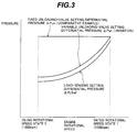
- Fig. 3 is a graph showing the operation of an unloading valve in the first embodiment in comparison with the operation of a conventional unloading valve.
- Fig. 4 is a hydraulic circuit diagram showing the configuration of a hydraulic drive system according to a second embodiment of the present invention.
- Fig. 5 is a diagram showing details of a flow rate detecting valve shown in Fig. 4.
- Figs. 6A to 6C are graphs showing the operation of a flow rate detecting valve shown in Fig. 4 in comparison with the operation of the flow rate detecting valve shown in Fig. 1.
- Fig. 7 is a graph showing the relationships of an engine rotational speed versus a maximum demanded flow rate of flow control valves and a maximum pump delivery rate in a conventional system.
- Fig. 8 is a graph showing the relationships of an engine rotational speed versus a maximum demanded flow rate of flow control valves and a maximum pump delivery rate as resulted from the provision of the flow rate detecting valve shown in Fig. 4.
- Fig. 9 is a graph showing the relationship between a total lever input amount and a flow rate passing through the flow control valves as resulted from the provision of the flow rate detecting valve shown in Fig. 4.
- Fig. 10 is a graph showing the relationship between a total lever input amount and a flow rate passing through the flow control valves as resulted from the provision of the flow rate detecting valve shown in Fig. 4.
- Fig. 11 is a graph showing the operation of an unloading valve in the second embodiment in comparison with the operation of the conventional unloading valve.
- Fig. 12 is a hydraulic circuit diagram showing the configuration of a hydraulic drive system according to a third embodiment of the present invention.
- Fig. 1 shows a hydraulic drive system according to a first embodiment of the present invention.
- the hydraulic drive system comprises an engine 1, a variable displacement hydraulic pump 2 driven by the engine 1, a plurality of actuators 3a, 3b, 3c driven by a hydraulic fluid delivered from the hydraulic pump 2, a valve apparatus 4 including a plurality of directional control valves 4a, 4b, 4c connected to a delivery line 100 of the hydraulic pump 2 for controlling flow rates and directions at and in which the hydraulic fluid is supplied from the hydraulic pump 2 to the respective actuators 3a, 3b, 3c, and a pump displacement control system 5 for controlling the displacement of the hydraulic pump 2, and an unloading valve 80 disposed in a branch line 102 communicating the delivery line 100 of the hydraulic pump 2 with a reservoir 101.
- the plurality of directional control valves 4a, 4b, 4c are made up of respectively a plurality of flow control valves 6a, 6b, 6c and a plurality of pressure compensating valves 7a, 7b, 7c for controlling differential pressures across the plurality of flow control valves 6a, 6b, 6c to become equal to each other.
- the plurality of pressure compensating valves 7a, 7b, 7c are of the pre-stage type installed upstream of the flow control valves 6a, 6b, 6c, respectively.
- the pressure compensating valve 7a has two pairs of opposing control pressure chambers 70a, 70b; 70c, 70d.
- Pressures upstream and downstream of the flow control valve 6a are introduced respectively to the control pressure chambers 70a, 70b, and a delivery pressure Ps of the hydraulic pump 2 and a maximum load pressure PLS among the plurality of actuators 3a, 3b, 3c are introduced respectively to the control pressure chambers 70c, 70d, whereby the differential pressure across the flow control valve 6a acts in the valve-closing direction and a differential pressure ⁇ PLS between the delivery pressure Ps of the hydraulic pump 2 and the maximum load pressure PLS among the plurality of actuators 3a, 3b, 3c acts in the valve-opening direction.
- the pressure compensating valve 7a controls the differential pressure across the flow control valve 6a with the differential pressure ⁇ PLS as a target differential pressure for pressure compensation.
- the pressure compensating valves 7b, 7c are also of the same construction.
- the pressure compensating valves 7a, 7b, 7c control the respective differential pressures across the flow control valves 6a, 6b, 6c with the same differential pressure ⁇ PLS as a target differential pressure
- the differential pressures across the flow control valves 6a, 6b, 6c are all controlled to become equal to the differential pressure ⁇ PLS and respective flow rates demanded by the flow control valves 6a, 6b, 6c are expressed by the products of the differential pressure ⁇ PLS and opening areas of those valves.
- the plurality of flow control valves 6a, 6b, 6c are provided with load ports 60a, 60b, 60c, respectively, through which load pressures of the actuators 3a, 3b, 3c are taken out during the operation of the actuators 3a, 3b, 3c.
- Maximum one of the load pressures taken out through the load ports 60a, 60b, 60c is detected by a signal line 10 via load lines 8a, 8b, 8c, 8d and shuttle valves 9a, 9b, the detected pressure being applied as the maximum load pressure PLS to the pressure compensating valves 7a, 7b, 7c.
- the hydraulic pump 2 is a swash plate pump wherein a delivery rate is increased by increasing a tilting angle of a swash plate 2a.
- the pump displacement control system 6 comprises a servo piston 20 for tilting the swash plate 2a of the hydraulic pump 2, and a tilting control unit 21 for driving the servo piston 20 to control the tilting angle of the swash plate 2a, thereby controlling the displacement of the hydraulic pump 2.
- the serve piston 20 is operated in accordance with a pressure introduced from the delivery line 100 (the delivery pressure Ps of the hydraulic pump 2) and a command pressure from the tilting control unit 21.
- the tilting control unit 21 includes a first tilting control valve 22 and a second tilting control valve 23.
- the first tilting control valve 22 is a horsepower control valve for reducing the delivery rate of the hydraulic pump 2 as the pressure introduced from the delivery line 100 (the delivery pressure Ps of the hydraulic pump 2) rises.
- the first tilting control valve 22 receives the delivery pressure Ps of the hydraulic pump 2, as an original pressure, and if the delivery pressure Ps of the hydraulic pump 2 is lower than a predetermined level set by a spring 22a, a spool 22b is moved to the right on the drawing, causing the delivery pressure Ps of the hydraulic pump 2 to be output as it is.
- the servo piston 20 is moved to the left on the drawing due to an area difference thereof between the opposite sides, whereupon the tilting angle of the swash plate 2a is increased to increase the delivery rate of the hydraulic pump 2.
- the delivery pressure Ps of the hydraulic pump 2 rises.
- the spool 22b is moved to the left on the drawing to reduce the delivery pressure Ps and a resulting reduced pressure is output as a command pressure. Accordingly, the servo piston 20 is moved to the right on the drawing, whereupon the tilting angle of the swash plate 2a is diminished to reduce the delivery rate Ps of the hydraulic pump 2.
- the second tilting control valve 23 is a load sensing control valve for controlling the differential pressure ⁇ PLS between the delivery pressure Ps of the hydraulic pump 2 and the maximum load pressure PLS among the actuators 3a, 3b, 3c to be maintained at the target differential pressure ⁇ PLSref.
- the second tilting control valve 23 comprises a spring 23a for setting a basic value of the target differential pressure ⁇ PLSref, a spool 23b, and a first operation driver 24 operated in accordance with the pressure introduced from the delivery line 100 (the delivery pressure Ps of the hydraulic pump 2) and the maximum load pressure PLS among the actuators 3a, 3b, 3c, for thereby moving the spool 23b.
- the first operation driver 24 comprises a piston 24a acting on the spool 23b and two hydraulic pressure chambers 24b, 24c divided by the piston 24a.
- the delivery pressure Ps of the hydraulic pump 2 is introduced to the hydraulic pressure chamber 24b, and the maximum load pressure PLS is introduced to the hydraulic pressure chamber 24c with the spring 23a built in the hydraulic pressure chamber 24c.
- the second tilting control valve 23 receives the output pressure of the first tilting control valve 22, as an original pressure.
- the spool 23b is moved by the first operation driver 24 to the left on the drawing, causing the output pressure of the first tilting control valve 22 to be output as it is.
- the output pressure of the first tilting control valve 22 is given by the delivery pressure Ps of the hydraulic pump 2, the delivery pressure Ps is applied as a command pressure to the servo piston 20.
- the servo piston 20 is therefore moved to the left on the drawing due to the area difference thereof between the opposite sides, whereupon the tilting angle of the swash plate 2a is increased to increase the delivery rate of the hydraulic pump 2.
- the delivery pressure Ps of the hydraulic pump 2 rises and the differential pressure ⁇ PLS also rises.
- the spool 23b is moved by the first operation driver 24 to the right on the drawing to reduce the output pressure of the first tilting control valve 22 and a resulting reduced pressure is output as a command pressure.
- the servo piston 20 is moved to the right on the drawing, whereupon the tilting angle of the swash plate 2a is diminished to reduce the delivery rate of the hydraulic pump 2.
- the differential pressure ⁇ PLS is maintained at the target differential pressure ⁇ PLSref.
- the differential pressures across the flow control valves 6a, 6b, 6c are controlled respectively by the pressure compensating valves 7a, 7b, 7c so as to become the same value, i.e., the differential pressure ⁇ PLS. Therefore, maintaining the differential pressure ⁇ PLS at the target differential pressure ⁇ PLSref, as explained above, eventually results in that the differential pressures across the flow control valves 6a, 6b, 6c are maintained at the target differential pressure ⁇ PLSref.
- the pump displacement control system 5 further comprises first setting modifying means 38 for modifying the target differential pressure ⁇ PLSref applied to the second tilting control valve 23 depending on change in rotational speed of the engine 1.
- the first setting modifying means 38 is made up of a fixed displacement hydraulic pump 30 driven by the engine 1 along with the variable displacement hydraulic pump 2, a throttle 50 in the form of a flow rate detecting valve disposed to intermediate between delivery lines 30a, 30b of the fixed displacement hydraulic pump 30, and a second operation driver 32 for modifying the target differential pressure ⁇ PLSref depending on a differential pressure ⁇ Pp across the throttle 50.
- the fixed displacement hydraulic pump 30 is one that is usually provided to serve as a pilot hydraulic fluid source.
- a relief valve 33 for specifying an original pressure supplied from the pilot hydraulic fluid source is connected to the delivery line 30b, and the delivery line 30b is further connected to a remote control valve (not shown) for producing a pilot pressure used to shift the flow control valves 6a, 6b, 6c, for example.
- the second operation driver 32 is an additional operation driver integrated with the first operation driver 24 of the second tilting control valve 23, and comprises a piston 32a acting on the piston 24a of the first operation driver 24 and two hydraulic pressure chambers 32b, 32c divided by the piston 32a.
- a pressure upstream of the throttle 50 is introduced to the hydraulic pressure chamber 32b via a pilot line 34a and a pressure downstream of the throttle 50 is introduced to the hydraulic pressure chamber 32c via a pilot line 34b, causing the piston 32a to urge the piston 24a to the left on the drawing by a force corresponding to the differential pressure ⁇ Pp across the throttle 50.
- the target differential pressure ⁇ PLSref provided by the second tilting control valve 23 is set in accordance with the basic value given by the spring 23a and the urging force of the piston 32a. As the differential pressure ⁇ Pp across the throttle 50 becomes smaller, the piston 32a pushes the piston 24a by a smaller force to reduce the target differential pressure ⁇ PLSref. As the differential pressure ⁇ Pp becomes larger, the piston 32a pushes the piston 24a by a larger force to increase the target differential pressure ⁇ PLSref.
- the differential pressure ⁇ Pp across the throttle 50 varies depending on the rotational speed of the engine 1.
- the first modifying changing means 38 thus modifies the target differential pressure ⁇ PLSref provided by the first tilting control valve 23 depending on the engine rotational speed.
- the unloading valve 80 controls the delivery pressure Ps of the hydraulic pump 2 so that the differential pressure ⁇ PLS between the delivery pressure Ps of the hydraulic pump 2 and the maximum load pressure PLS among the plurality of actuators 3a, 3b, 3c is maintained at a differential pressure ⁇ Pun higher than the target differential pressure ⁇ Pun in load sensing control (referred to as "load-sensing setting differential pressure" hereinafter).
- the unloading valve 80 has a first control pressure chamber 80b applying pressure to act in the direction to increase an opening degree of a valve body 80a, a second control pressure chamber 80c applying pressure to act in the direction to reduce the opening degree, a spring 80d for urging the valve body 80a in the direction to reduce the opening degree, a third control pressure chamber 80e applying pressure to act in the direction to reduce the opening degree, and a fourth control pressure chamber 80f applying pressure to act in the direction to increase the opening degree.
- the delivery pressure Ps of the variable displacement hydraulic pump 2 is introduced to the first control pressure chamber 80b via a pilot line 85a, the maximum load pressure PLS is introduced to the second control pressure chamber 80b via a pilot line 85b, the pressure upstream of the throttle 50 is introduced to the third control pressure chamber 80e via a pilot line 86a, and the pressure downstream of the throttle 50 is introduced to the fourth control pressure chamber 80f via a pilot line 86b.
- the third and fourth control pressure chambers 80e, 80f and the pilot lines 86a, 86b jointly constitute second setting modifying means for changing the setting differential pressure ⁇ Pun held by the unloading valve 80 depending on the rotational speed of the engine 1 in match with change in the load-sensing setting differential pressure ⁇ PLsref provided by the first setting modifying means 38.
- the pressure in the delivery line 100 is controlled to the setting differential pressure ⁇ Pun that is higher than the load-sensing setting differential pressure ⁇ PLSref by the setting pressure Psp of the spring 80d.
- the setting differential pressure ⁇ Pun held by the unloading valve 80 is determined based on the load-sensing setting differential pressure ⁇ PLSref, the setting differential pressure ⁇ Pun held by the unloading valve 80 also varies as the load-sensing setting differential pressure ⁇ PLSref varies depending on change in rotational speed of the engine 1.
- the setting differential pressure ⁇ Pun is always given as a value higher than the load-sensing setting differential pressure ⁇ PLSref by the setting pressure Psp of the spring 80d.
- the unloading valve 80 will be described below in comparison with the operation of a conventional unloading valve for holding the setting differential pressure ⁇ Pun constant.
- the conventional unloading valve is called a fixed unloading valve and the unloading valve in the present invention is called a variable unloading valve.
- the fixed displacement hydraulic pump 30 delivers the hydraulic fluid at a flow rate Qp expressed by the product of a rotational speed N of the engine 1 and a pump displacement Cm.
- Qp CmN
- the differential pressure ⁇ Pp across the throttle 50 increases following a curve of secondary degree with respect to the delivery rate Qp of the hydraulic pump 30 or the rotational speed N of the engine 1 based on the formula (3), as shown in Fig. 2A. Also, since the relationship of ⁇ PLSref ⁇ ⁇ Pp holds by virtue of the second operation driver 32, the load-sensing setting differential pressure ⁇ PLSref also increases following a curve of secondary degree with respect to the delivery rate Qp of the hydraulic pump 30 or the rotational speed N of the engine 1, as shown in Fig. 2A.
- the target differential pressure ⁇ PLSref across the flow control valve 6a is given by the differential pressure ⁇ Pp across the throttle 50 ( ⁇ PLSref ⁇ ⁇ Pp).
- the demanded flow rate Qv can be related to the rotational speed N of the engine 1 by the following formula: Qv ⁇ (Av/Ap)CmN
- Fig. 3 shows the relationship between the load-sensing setting differential pressure ⁇ PLSref and the setting differential pressure ⁇ Pun held by the variable unloading valve 80 in the present invention resulted when the load-sensing setting differential pressure ⁇ PLSref varies depending on the engine rotational speed as explained above, in comparison with that resulted in the case of using the fixed unloading valve.
- the load-sensing setting differential pressure ⁇ PLSref varies following a curve of secondary degree depending on the engine rotational speed in a like way as shown in Fig. 2A. Since the setting differential pressure ⁇ Pun held by the variable unloading valve in the present invention varies while keeping a value higher than the load-sensing setting differential pressure ⁇ PLSref by the setting pressure Psp of the spring 80d, the setting differential pressure ⁇ Pun also varies following a curve of secondary degree depending on the engine rotational speed similarly to the load-sensing setting differential pressure ⁇ PLSref. On the other hand, the setting differential pressure ⁇ Pun held by the fixed unloading valve is constant regardless of change in the engine rotational speed.
- both the conventional fixed unloading valve and the variable unloading valve in the present invention hold the setting differential pressures ⁇ Pun each set to a value slightly higher than the load-sensing setting differential pressure ⁇ PLSref.
- the two setting differential pressures have the same value, the setting differential pressure held by the fixed unloading valve is uniquely fixed, whereas the setting differential pressure held by the variable unloading valve in the present invention is given as a variable value higher than the load-sensing setting differential pressures ⁇ PLSref by the setting pressure Psp of the spring 80d.
- the setting differential pressure ⁇ Pun held by the conventional fixed unloading valve has a value much higher than the load-sensing setting differential pressure ⁇ PLSref.
- a difference between the setting differential pressure ⁇ Pun held by the variable unloading valve in the present invention and the load-sensing setting differential pressure ⁇ PLSref is not changed because the setting differential pressure ⁇ Pun held by the variable unloading valve in the present invention varies while keeping a value higher than the load-sensing setting differential pressure ⁇ PLSref by the setting pressure Psp of the spring 80d.
- the difference between the load-sensing setting differential pressure ⁇ PLSref and the setting differential pressure ⁇ Pun held by the unloading valve is not increased when the rotational speed of the engine 1 is lowered, and hence stability of the system can be ensured even at low rotational speeds of the engine 1.
- first setting modifying means 38A in a pump displacement control system 5A of this embodiment is constituted by a flow rate detecting valve 31 having an adjustable fixed throttle 31a disposed in the delivery line of the fixed displacement hydraulic pump 30 instead of the fixed throttle 50 shown in Fig. 1.
- the flow rate detecting valve 31 is constructed so as to adjust an operating condition of the fixed throttle 31a in accordance with a differential pressure across the flow rate detecting valve 31 itself. More specifically, the flow rate detecting valve 31 has a valve body 31b provided with the fixed throttle 31a.
- a differential pressure ⁇ Pp across the flow rate detecting valve 31 introduced to control pressure chambers 31d, 31e is not larger than a differential pressure corresponding to the resilient force of a spring 31c (referred to as a setting differential pressure hereinafter)
- the flow rate detecting valve 31 is held in a left-hand position on the drawing where the fixed throttle 31a develops its function.
- the differential pressure ⁇ Pp across the flow rate detecting valve 31 becomes higher than the setting differential pressure, the flow rate detecting valve 31 is shifted to a right-hand open position on the drawing from the left-hand position on the drawing where the fixed throttle 31a develops its function.
- the relationship between the rotational speed of the engine 1 and the load-sensing target differential pressure ⁇ PLSref can be provided in other more complex pattern than the simple proportional relationship provided by the fixed throttle 40.
- the second setting modifying means constituted by the control pressure chambers 80e, 80f of the unloading valve 80 also functions to vary the setting differential pressure ⁇ Pun held by the unloading valve 80 depending on change in the load-sensing setting differential pressure ⁇ PLSref, whereby similar advantages as in the first embodiment can be obtained.
- a piston serving as the valve body 31b moves within a casing 31f and the piston 31b has a small hole formed therein to serve as the fixed throttle 31a.
- the small hole has an opening area Ap of the fixed throttle 31a.
- the casing 31f has a cylindrical shape and a gap having an opening area Af is defined between an outer circumferential surface of the piston 31b and an inner circumferential surface of the casing 31f.
- the opening area Af is selected to a large value enough to prevent the gap from serving as a throttle in fact.
- the piston 31b is supported by the spring 31c, and a resilient force F of the spring 31c acts on the piston 31b in the direction to close an inlet of the casing 31f and to make the function of the fixed throttle 31a effective.
- the differential pressure ⁇ Pp across the flow rate detecting valve 31 introduced to the control pressure chambers 31d, 31e varies depending on the rotational speed of the engine 1. Specifically, as the rotational speed of the engine 1 lowers, the delivery rate of the hydraulic pump 30 is reduced and the differential pressure ⁇ Pp across the flow rate detecting valve 31 is also reduced. Accordingly, when the engine rotational speed is lower than an engine rotational speed corresponding to the setting differential pressure specified by the spring 31c (referred to as a setting rotational speed hereinafter), the flow rate detecting valve 31 is held in a position where the fixed throttle 31a develops its function (i.e., the left-hand position in Fig. 4), and when the engine rotational speed exceeds the setting rotational speed, the flow rate detecting valve 31 controls a throttle condition so as to maintain the differential pressure ⁇ Pp across the flow rate detecting valve 31 at the setting differential pressure specified by the spring 31c.
- a setting rotational speed an engine rotational speed corresponding to the setting differential pressure specified by the spring 31c
- control pressure chambers 31d, 31e and the spring 31c function as throttle adjusting means for making the fixed throttle 31a effective when the engine rotational speed is in a region including the lowest rotational speed, and controlling the fixed throttle 31a to reduce an increase rate of the differential pressure ⁇ Pp across the flow rate detecting valve 31 when the engine rotational speed rises to the setting rotational speed lower than the rated rotational speed.
- the flow rate detecting valve 31 is constructed to have a larger opening area when the engine rotational speed is in the region including the rated rotational speed than when it is in the region including the lowest rotational speed.
- the opening area Ap of the fixed throttle 31a is set smaller than that of the fixed throttle 50 in the first embodiment and consequently an increase rate of the differential pressure ⁇ Pp across the fixed throttle 31a is higher than the case of using the fixed throttle 50 indicated by a dotted line.
- the flow rate detecting valve 31 When the engine rotational speed N exceeds the setting rotational speed Ns, the flow rate detecting valve 31 operates so as to maintain the differential pressure ⁇ Pp across itself at the setting differential pressure specified by the spring 31c.
- the differential pressure ⁇ Pp across the flow rate detecting valve 31 is therefore kept substantially constant at ⁇ Ppmax, as shown in Fig. 6A.
- a flow rate Qv demanded by each of the flow control valves 6a, 6b, 6c increases following a curve of secondary degree with respect to the target differential pressure ⁇ PLSref, as shown in Fig. 6B.
- the demanded flow rate Qv varies with respect to the rotational speed N of the engine 1, as shown in Fig. 6C. More specifically, when the engine rotational speed N is lower than the setting rotational speed Ns, the change of ⁇ Pp represented by a curve of secondary degree shown in Fig. 6A and the change of the demanded flow rate Qv represented by a curve of secondary degree shown in Fig. 6B cancel each other. As a result, the demanded flow rate Qv increases almost linearly with respect to the rotational speed N of the engine 1. A gradient of the linear line (change rate) is however greater than in the case of using the fixed throttle 50 indicated by a dotted line. When the engine rotational speed N exceeds the setting rotational speed Ns, ⁇ Pp in Fig. 6A is kept substantially constant at ⁇ Ppmax and therefore the demanded flow rate Qv is also kept substantially constant correspondingly.
- Fig. 6C when driving a plurality of, e.g., two or three, actuators, the relationship of Fig. 6C is obtained for each of the flow control valves 6a, 6b or 6a, 6b, 6c, and the relationship between the rotational speed N of the engine 1 and a total of respective demanded rates Qv is given as one resulted from simply adding the relationship of Fig. 6C two or three times.
- the relationships of the rotational speed N of the engine 1 versus a total maximum demanded flow rate Qvtotal of any two of the flow control valves 6a, 6b, 6c, e.g., the flow control valves 6a, 6b, (i.e., total of the flow rates Qv demanded by the flow control valves 6a, 6b at maximum opening areas thereof) and a maximum delivery rate Qsmax of the variable displacement hydraulic pump 2 are represented as shown Fig. 7.
- the relationships of the rotational speed N of the engine 1 versus a total maximum demanded flow rate Qvtotal of any two of the flow control valves 6a, 6b, 6c, e.g., the flow control valves 6a, 6b, (i.e., total of the flow rates Qv demanded by the flow control valves 6a, 6b at maximum opening areas thereof) and a maximum delivery rate Qsmax of the variable displacement hydraulic pump 2 are represented as shown Fig. 8 based on the characteristic of Fig. 6C.
- the setting 2 represents an engine rotational speed suitable for fine operation. Specifically, since it is generally said that a rotational speed lower than the middle between the rated rotational speed and the lowest rotational speed is suitable for fine operation, the setting 2 corresponds to a rotational speed lower than the middle rotational speed.
- the rated rotational speed of the engine 1 is 2,200 rpm and the lowest rotational speed (idling rotational speed) is 1,000 rpm
- the middle rotational speed is 1,600 rpm
- the setting 2 represents a rotational speed lower than 1,600 rpm.
- the setting 2 represents 1,200 rpm.
- the setting 1 represents the rated rotational speed of 2,200 rpm.
- the flow rate detecting valve 31 is constructed to have a larger opening area when the engine rotational speed is in the region including the rated rotational speed than when it is in the region including the lowest rotational speed.
- the first setting modifying means 38A made up of the flow rate detecting valve 31, the fixed displacement hydraulic pump 30 and the second operation driver 32 detects a rotational speed of the engine 1, and when the detected engine rotational speed is in the region including the lowest rotational speed, the means 38A modifies the setting value ⁇ PLSref of the pump displacement control system 5 so that the total maximum demanded flow rate Qvtotal of the plural flow control valves 6a, 6b, which is expressed based on the products of the differential pressure ⁇ PLS and the respective opening areas of the plural flow control valves 6a, 6b, is smaller than the maximum delivery rate Qsmax of the hydraulic pump 2 determined by the engine rotational speed at that time.
- Fig. 9 shows characteristics of the setting modifying means 38A in terms of the relationship between a total lever input amount applied from an operator to the flow control valves 6a, 6b and the total demanded flow rate of the flow control valves 6a, 6b (total flow rate passing therethrough).
- Fig. 11 shows the relationship between the load-sensing setting differential pressure ⁇ PLSref and the setting differential pressure ⁇ Pun held by the variable unloading valve 80 in the present invention resulted when the load-sensing setting differential pressure ⁇ PLSref varies depending on the engine rotational speed as explained above, in comparison with that resulted in the case of using the fixed unloading valve.
- the load-sensing setting differential pressure ⁇ PLSref varies following a curve of secondary degree depending on the engine rotational speed until the setting rotational speed Ns in a like way as shown in Fig. 6A, and ⁇ PLSref is then held almost constant at the engine rotational speed not lower than Ns.
- the setting differential pressure ⁇ Pun held by the variable unloading valve 80 varies likewise in this embodiment while keeping a value higher than the load-sensing setting differential pressure ⁇ PLSref by the setting pressure Psp of the spring 80d, the setting differential pressure ⁇ Pun also varies following a curve of secondary degree depending on the engine rotational speed until the setting rotational speed Ns and is then held constant at the engine rotational speed not lower than Ns similarly to the load-sensing setting differential pressure ⁇ PLSref.
- the setting differential pressure ⁇ Pun held by the fixed unloading valve is constant all over the range of the engine rotational speed.
- the setting differential pressure ⁇ Pun held by the unloading valve can be adjusted correspondingly.
- the difference between the load-sensing setting differential pressure ⁇ PLSref and the setting differential pressure ⁇ Pun held by the unloading valve is not increased when the rotational speed of the engine 1 is lowered, and hence stability of the system can be ensured even at low rotational speeds of the engine 1.
- a saturation phenomenon is improved in consideration of the engine rotational speed such that when the engine rotational speed is set to a low value, good operability in fine operation can be achieved, and when the engine rotational speed is set to a high value, a powerful feeling can be realized in the operation with good response. It is thus possible to establish the system setting adapted for the purpose of work intended by the operator based on setting of the engine rotational speed.
- this embodiment can provide a practical flow rate detecting valve because the casing 31Bf of the flow rate detecting valve 31B has a simple cylindrical shape and hence can be manufactured very easily.
- FIG. 12 A third embodiment of the present invention will be described below with reference to Fig. 12.
- equivalent members to those in Figs. 1 and 4 are denoted by the same reference numerals.
- first setting modifying means 38B includes a pressure control valve 40 for outputting a signal pressure which corresponds to the differential pressure ⁇ Pp across the flow rate detecting valve 31.
- the pressure control valve 40 has a control pressure chamber 40b urging a valve body 40a in the direction to increase pressure, and control pressure chambers 40c, 40d urging the valve body 40a in the direction to reduce pressure.
- a pressure upstream of the flow rate detecting valve 31 is introduced to the control pressure chamber 40b, whereas a pressure downstream of the flow rate detecting valve 31 and an output pressure of the pressure control valve 40 itself are introduced to the control pressure chambers 40c, 40d, respectively.
- the signal pressure corresponding to the differential pressure ⁇ Pp across the variable throttle 31a is produced as an absolute pressure based on balance among the above pressures.
- the signal pressure is introduced to a hydraulic pressure chamber 32b of a second operation driver 32B via a pilot line 41a, and a hydraulic pressure chamber 32c of the second operation driver 32B is communicated with a reservoir via a pilot line 41b.
- a pressure control valve 45 for generating a signal pressure which corresponds to the differential pressure ⁇ PLS between the delivery pressure Ps of the hydraulic pump 2 and the maximum load pressure PLS among the plurality of actuators 3a, 3b, 3c.
- the pressure control valve 45 has a control pressure chamber 45b urging a valve body 45a in the direction to increase pressure, and control pressure chambers 45c, 45d urging the valve body 45a in the direction to reduce pressure.
- the delivery pressure Ps of the hydraulic pump 2 is introduced to the control pressure chamber 45b, whereas the maximum load pressure PLS and an output pressure of the pressure control valve 45 itself are introduced to the control pressure chambers 45c, 45d, respectively.
- the signal pressure corresponding to the differential pressure ⁇ PLS between the pump delivery pressure Ps and the maximum load pressure PLS is produced as an absolute pressure based on balance among those pressures.
- An unloading valve 80B has one control pressure chamber 80g applying pressure to act in the direction to increase an opening degree thereof instead of the first and second two control pressure chambers 80b, 80c shown in Fig. 1, and one control pressure chamber 80h applying pressure to act in the direction to reduce the opening degree thereof instead of the third and fourth two control pressure chambers 80e, 80f shown in Fig. 1.
- the signal pressure from the pressure control valve 45 is introduced to the control pressure chamber 80g via a pilot line 87a, and the signal pressure from the pressure control valve 40 is introduced to the control pressure chamber 80f via a pilot line 87b.
- the second operation driver 32B operates likewise to modify the target differential pressure ⁇ PLSref depending on the differential pressure ⁇ Pp across the flow rate detecting valve 31, and the unloading valve 80B operates to modify the setting differential pressure ⁇ Pun in match with the target differential pressure ⁇ PLSref depending on the differential pressure ⁇ Pp across the flow rate detecting valve 31.
- this embodiment can also provide similar operating advantages as obtainable with the second embodiment.
- the first setting modifying means 38B requires only one pilot line 41a for introducing the signal pressure from the flow rate detecting valve 31 to the second operation driver 32 and the unloading valve 80B requires only two pilot line 87a, 87b for introducing the signal pressure, resulting in a simpler circuit configuration.
- each of the pressure control valves 40, 45 detects the differential pressure as an absolute pressure, the signal pressure is produced at a lower level than the case of detecting the individual pressure as they are, resulting in that the pilot lines 41a, 41b, 87a, 87b can be formed of hoses or the like adapted for relatively low pressures and the circuit configuration can be achieved with a lower cost.
- the pressure compensating valves have been described as being of the pre-stage type installed upstream of the flow control valves, the pressure compensating valves may be of the post-stage type installed downstream of the flow control valves to control respective output pressures of all the flow control valves to the same maximum load pressure, thereby controlling respective differential pressures across the flow control valves to the same differential pressure ⁇ PLS.
Landscapes
- Engineering & Computer Science (AREA)
- General Engineering & Computer Science (AREA)
- Mining & Mineral Resources (AREA)
- Civil Engineering (AREA)
- Structural Engineering (AREA)
- Mechanical Engineering (AREA)
- Physics & Mathematics (AREA)
- Fluid Mechanics (AREA)
- Fluid-Pressure Circuits (AREA)
Applications Claiming Priority (4)
| Application Number | Priority Date | Filing Date | Title |
|---|---|---|---|
| JP31085096 | 1996-11-21 | ||
| JP31085096 | 1996-11-21 | ||
| JP310850/96 | 1996-11-21 | ||
| PCT/JP1997/004154 WO1998022717A1 (fr) | 1996-11-21 | 1997-11-14 | Dispositif d'entrainement hydraulique |
Publications (3)
| Publication Number | Publication Date |
|---|---|
| EP0877168A1 true EP0877168A1 (fr) | 1998-11-11 |
| EP0877168A4 EP0877168A4 (fr) | 2000-09-20 |
| EP0877168B1 EP0877168B1 (fr) | 2004-02-11 |
Family
ID=18010151
Family Applications (1)
| Application Number | Title | Priority Date | Filing Date |
|---|---|---|---|
| EP97912461A Expired - Lifetime EP0877168B1 (fr) | 1996-11-21 | 1997-11-14 | Systeme de commande hydraulique |
Country Status (4)
| Country | Link |
|---|---|
| US (1) | US6192681B1 (fr) |
| EP (1) | EP0877168B1 (fr) |
| DE (1) | DE69727552T2 (fr) |
| WO (1) | WO1998022717A1 (fr) |
Cited By (5)
| Publication number | Priority date | Publication date | Assignee | Title |
|---|---|---|---|---|
| WO2000073664A1 (fr) * | 1999-05-28 | 2000-12-07 | Hitachi Construction Machinery Co., Ltd. | Dispositif de regulation du debit nominal d'une pompe et dispositif a soupape |
| WO2001051820A1 (fr) * | 2000-01-12 | 2001-07-19 | Hitachi Construction Machinery Co., Ltd. | Engin a commande hydraulique |
| EP2199622A3 (fr) * | 2008-12-18 | 2013-03-06 | Deere & Company | Système hydraulique |
| EP2944817A4 (fr) * | 2013-03-27 | 2016-12-14 | Kyb Corp | Dispositif de régulation de débit de décharge de pompe |
| DE102009010483B4 (de) | 2009-02-25 | 2019-10-17 | Linde Hydraulics Gmbh & Co. Kg | Regelventileinrichtung eines hydrostatischen Antriebssystems |
Families Citing this family (10)
| Publication number | Priority date | Publication date | Assignee | Title |
|---|---|---|---|---|
| US6293765B1 (en) * | 2000-05-08 | 2001-09-25 | Sauer-Danfoss Inc. | Tandem fixed displacement pump with torque control |
| JP4209705B2 (ja) * | 2003-03-17 | 2009-01-14 | 日立建機株式会社 | 作業機の油圧回路 |
| US6988554B2 (en) * | 2003-05-01 | 2006-01-24 | Cooper Cameron Corporation | Subsea choke control system |
| CA2487461A1 (fr) * | 2003-11-10 | 2005-05-10 | Timberjack Inc. | Systeme de controle de pression pilote anti-calage pour systemes a centre ouvert |
| DE112005000052B4 (de) * | 2004-07-14 | 2010-01-14 | Komatsu Ltd. | Steuervorrichtung für eine Arbeitsmaschinen-Hydraulikpumpe eines Arbeitsfahrzeugs |
| CN103765019B (zh) | 2011-08-31 | 2016-03-23 | 日立建机株式会社 | 工程机械的液压驱动装置 |
| US20130168073A1 (en) * | 2011-12-30 | 2013-07-04 | Cnh America Llc | Work vehicle fluid heating system |
| JP6434395B2 (ja) * | 2015-10-23 | 2018-12-05 | 株式会社アドヴィックス | 液圧制御装置 |
| US12411503B2 (en) | 2023-01-13 | 2025-09-09 | Hamilton Sundstrand Corporation | High turn down ratio direct control for variable displacement pumps with flow sensing |
| US12286967B2 (en) * | 2023-01-13 | 2025-04-29 | Hamilton Sundstrand Corporation | High turn down ratio direct control for variable displacement pumps |
Family Cites Families (16)
| Publication number | Priority date | Publication date | Assignee | Title |
|---|---|---|---|---|
| DE2754430A1 (de) | 1977-12-07 | 1979-06-13 | Bosch Gmbh Robert | Steuereinrichtung fuer mindestens zwei verstellbare pumpen |
| DE3321483A1 (de) * | 1983-06-14 | 1984-12-20 | Linde Ag, 6200 Wiesbaden | Hydraulische einrichtung mit einer pumpe und mindestens zwei von dieser beaufschlagten verbrauchern hydraulischer energie |
| JP2578371B2 (ja) * | 1989-09-22 | 1997-02-05 | 株式会社小松製作所 | 可変容量ポンプの容量制御装置 |
| JP2828490B2 (ja) | 1990-06-19 | 1998-11-25 | 日立建機株式会社 | ロードセンシング油圧駆動回路の制御装置 |
| JPH04119604A (ja) | 1990-09-11 | 1992-04-21 | Fuji Denki Kk | ボンド磁石を製造する方法 |
| WO1992006306A1 (fr) | 1990-09-28 | 1992-04-16 | Hitachi Construction Machinery Co., Ltd. | Systeme de commande pour pompe hydraulique |
| JP3115887B2 (ja) | 1990-09-28 | 2000-12-11 | 株式会社小松製作所 | クローズドセンタ・ロードセンシングシステムにおけるポンプの吐出容積の可変回路 |
| JPH04258508A (ja) | 1991-02-07 | 1992-09-14 | Sumitomo Constr Mach Co Ltd | 建設機械の油圧駆動装置 |
| JP2526440Y2 (ja) * | 1991-04-09 | 1997-02-19 | 住友建機株式会社 | ロードセンシング油圧回路 |
| JPH0533776A (ja) | 1991-07-31 | 1993-02-09 | Komatsu Ltd | 可変容量型油圧ポンプの容量制御装置 |
| JPH0533775A (ja) | 1991-07-31 | 1993-02-09 | Komatsu Ltd | 可変容量型油圧ポンプの容量制御装置 |
| JPH0599126A (ja) | 1991-10-07 | 1993-04-20 | Komatsu Ltd | 可変容量型油圧ポンプの容量制御装置 |
| JP3104809B2 (ja) | 1992-01-16 | 2000-10-30 | 日立建機株式会社 | 油圧作業機の油圧駆動装置 |
| EP0597109B1 (fr) | 1992-03-09 | 1996-12-18 | Hitachi Construction Machinery Co., Ltd. | Systeme de commande hydraulique |
| JPH06221305A (ja) | 1993-01-25 | 1994-08-09 | Kubota Corp | 建機の油圧回路構造 |
| JPH0742705A (ja) | 1993-07-30 | 1995-02-10 | Yutani Heavy Ind Ltd | 作業機械の油圧装置 |
-
1997
- 1997-11-14 WO PCT/JP1997/004154 patent/WO1998022717A1/fr not_active Ceased
- 1997-11-14 EP EP97912461A patent/EP0877168B1/fr not_active Expired - Lifetime
- 1997-11-14 US US09/077,552 patent/US6192681B1/en not_active Expired - Lifetime
- 1997-11-14 DE DE69727552T patent/DE69727552T2/de not_active Expired - Lifetime
Cited By (8)
| Publication number | Priority date | Publication date | Assignee | Title |
|---|---|---|---|---|
| WO2000073664A1 (fr) * | 1999-05-28 | 2000-12-07 | Hitachi Construction Machinery Co., Ltd. | Dispositif de regulation du debit nominal d'une pompe et dispositif a soupape |
| US6422009B1 (en) | 1999-05-28 | 2002-07-23 | Hitachi Construction Machinery Co., Ltd. | Pump capacity control device and valve device |
| WO2001051820A1 (fr) * | 2000-01-12 | 2001-07-19 | Hitachi Construction Machinery Co., Ltd. | Engin a commande hydraulique |
| EP1162374A4 (fr) * | 2000-01-12 | 2002-10-30 | Hitachi Construction Machinery | Engin a commande hydraulique |
| US6584770B2 (en) | 2000-01-12 | 2003-07-01 | Hitachi Construction Machinery Co., Ltd. | Hydraulic drive system |
| EP2199622A3 (fr) * | 2008-12-18 | 2013-03-06 | Deere & Company | Système hydraulique |
| DE102009010483B4 (de) | 2009-02-25 | 2019-10-17 | Linde Hydraulics Gmbh & Co. Kg | Regelventileinrichtung eines hydrostatischen Antriebssystems |
| EP2944817A4 (fr) * | 2013-03-27 | 2016-12-14 | Kyb Corp | Dispositif de régulation de débit de décharge de pompe |
Also Published As
| Publication number | Publication date |
|---|---|
| WO1998022717A1 (fr) | 1998-05-28 |
| US6192681B1 (en) | 2001-02-27 |
| EP0877168B1 (fr) | 2004-02-11 |
| EP0877168A4 (fr) | 2000-09-20 |
| DE69727552T2 (de) | 2004-12-16 |
| DE69727552D1 (de) | 2004-03-18 |
Similar Documents
| Publication | Publication Date | Title |
|---|---|---|
| US6584770B2 (en) | Hydraulic drive system | |
| US4967557A (en) | Control system for load-sensing hydraulic drive circuit | |
| EP0877168B1 (fr) | Systeme de commande hydraulique | |
| US5056312A (en) | Hydraulic drive system for construction machines | |
| US6105367A (en) | Hydraulic drive system | |
| US4945723A (en) | Flow control valves for hydraulic motor system | |
| EP0366815B1 (fr) | Unite d'entrainement hydraulique pour engin de construction | |
| EP0503073B1 (fr) | Systeme de commande hydraulique dans un engin de chantier | |
| JPWO2000073664A1 (ja) | ポンプ容量制御装置及び弁装置 | |
| US5150574A (en) | Hydraulic drive system for civil engineering and construction machine | |
| EP0667452B1 (fr) | Dispositif de commande de debit pour pompe hydraulique a debit variable | |
| JP2001323902A (ja) | 油圧駆動装置 | |
| US4938022A (en) | Flow control system for hydraulic motors | |
| JP4976920B2 (ja) | ポンプ吐出量制御装置 | |
| JPH04136507A (ja) | 油圧回路 | |
| EP0477370A1 (fr) | Vanne et dispositif d'entrainement hydraulique | |
| US6772590B2 (en) | Hydraulic driving device | |
| GB2271870A (en) | A hydrostatic drive system | |
| JP3910280B2 (ja) | 油圧駆動装置 | |
| US5245828A (en) | Hydraulic drive system for civil engineering and construction machine | |
| JP3647625B2 (ja) | 油圧駆動装置 | |
| US5438832A (en) | Variable displacement pump with adjustment responsive to drive motor speed | |
| JP2721384B2 (ja) | 作業機械の油圧回路 | |
| JPH068641B2 (ja) | 油圧回路 | |
| JPH05346101A (ja) | 建設機械の油圧駆動装置 |
Legal Events
| Date | Code | Title | Description |
|---|---|---|---|
| PUAI | Public reference made under article 153(3) epc to a published international application that has entered the european phase |
Free format text: ORIGINAL CODE: 0009012 |
|
| 17P | Request for examination filed |
Effective date: 19980812 |
|
| AK | Designated contracting states |
Kind code of ref document: A1 Designated state(s): DE FR GB IT NL SE |
|
| A4 | Supplementary search report drawn up and despatched |
Effective date: 20000808 |
|
| AK | Designated contracting states |
Kind code of ref document: A4 Designated state(s): DE FR GB IT NL SE |
|
| RIC1 | Information provided on ipc code assigned before grant |
Free format text: 7F 15B 11/00 A, 7E 02F 9/22 B |
|
| GRAH | Despatch of communication of intention to grant a patent |
Free format text: ORIGINAL CODE: EPIDOS IGRA |
|
| RAP1 | Party data changed (applicant data changed or rights of an application transferred) |
Owner name: HITACHI CONSTRUCTION MACHINERY CO., LTD. |
|
| GRAS | Grant fee paid |
Free format text: ORIGINAL CODE: EPIDOSNIGR3 |
|
| RBV | Designated contracting states (corrected) |
Designated state(s): DE GB IT NL |
|
| GRAA | (expected) grant |
Free format text: ORIGINAL CODE: 0009210 |
|
| RTI1 | Title (correction) |
Free format text: HYDRAULIC DRIVE SYSTEM |
|
| AK | Designated contracting states |
Kind code of ref document: B1 Designated state(s): DE GB IT NL |
|
| REG | Reference to a national code |
Ref country code: GB Ref legal event code: FG4D |
|
| REF | Corresponds to: |
Ref document number: 69727552 Country of ref document: DE Date of ref document: 20040318 Kind code of ref document: P |
|
| PLBE | No opposition filed within time limit |
Free format text: ORIGINAL CODE: 0009261 |
|
| STAA | Information on the status of an ep patent application or granted ep patent |
Free format text: STATUS: NO OPPOSITION FILED WITHIN TIME LIMIT |
|
| 26N | No opposition filed |
Effective date: 20041112 |
|
| PGFP | Annual fee paid to national office [announced via postgrant information from national office to epo] |
Ref country code: NL Payment date: 20161010 Year of fee payment: 20 Ref country code: DE Payment date: 20161108 Year of fee payment: 20 Ref country code: GB Payment date: 20161109 Year of fee payment: 20 |
|
| REG | Reference to a national code |
Ref country code: DE Ref legal event code: R082 Ref document number: 69727552 Country of ref document: DE Representative=s name: MERH-IP MATIAS ERNY REICHL HOFFMANN PATENTANWA, DE Ref country code: DE Ref legal event code: R081 Ref document number: 69727552 Country of ref document: DE Owner name: HITACHI CONSTRUCTION MACHINERY TIERRA CO., LTD, JP Free format text: FORMER OWNER: HITACHI CONSTRUCTION MACHINERY CO., LTD., TOKIO/TOKYO, JP |
|
| PGFP | Annual fee paid to national office [announced via postgrant information from national office to epo] |
Ref country code: IT Payment date: 20161122 Year of fee payment: 20 |
|
| REG | Reference to a national code |
Ref country code: NL Ref legal event code: PD Owner name: HITACHI CONSTRUCTION MACHINERY TIERRA CO., LTD.; J Free format text: DETAILS ASSIGNMENT: CHANGE OF OWNER(S), ASSIGNMENT; FORMER OWNER NAME: HITACHI CONSTRUCTION MACHINERY CO. LTD. Effective date: 20170327 |
|
| REG | Reference to a national code |
Ref country code: GB Ref legal event code: 732E Free format text: REGISTERED BETWEEN 20170817 AND 20170823 |
|
| REG | Reference to a national code |
Ref country code: DE Ref legal event code: R071 Ref document number: 69727552 Country of ref document: DE |
|
| REG | Reference to a national code |
Ref country code: NL Ref legal event code: MK Effective date: 20171113 |
|
| REG | Reference to a national code |
Ref country code: GB Ref legal event code: PE20 Expiry date: 20171113 |
|
| PG25 | Lapsed in a contracting state [announced via postgrant information from national office to epo] |
Ref country code: GB Free format text: LAPSE BECAUSE OF EXPIRATION OF PROTECTION Effective date: 20171113 |