EP0477520B1 - Bande de contact pour un contact commun d'une pluralité d'aggregats qui sont excités électriquement pour moteurs à moteurs à combustion interne - Google Patents
Bande de contact pour un contact commun d'une pluralité d'aggregats qui sont excités électriquement pour moteurs à moteurs à combustion interne Download PDFInfo
- Publication number
- EP0477520B1 EP0477520B1 EP91113545A EP91113545A EP0477520B1 EP 0477520 B1 EP0477520 B1 EP 0477520B1 EP 91113545 A EP91113545 A EP 91113545A EP 91113545 A EP91113545 A EP 91113545A EP 0477520 B1 EP0477520 B1 EP 0477520B1
- Authority
- EP
- European Patent Office
- Prior art keywords
- contact strip
- housing
- plug
- damping element
- face
- Prior art date
- Legal status (The legal status is an assumption and is not a legal conclusion. Google has not performed a legal analysis and makes no representation as to the accuracy of the status listed.)
- Expired - Lifetime
Links
- 238000002485 combustion reaction Methods 0.000 title claims description 16
- 239000000446 fuel Substances 0.000 claims description 54
- 238000013016 damping Methods 0.000 claims description 52
- 238000002347 injection Methods 0.000 claims description 19
- 239000007924 injection Substances 0.000 claims description 19
- 239000013013 elastic material Substances 0.000 claims description 4
- 230000000717 retained effect Effects 0.000 claims 1
- 238000005304 joining Methods 0.000 description 10
- 238000000034 method Methods 0.000 description 10
- 239000004020 conductor Substances 0.000 description 6
- 238000004519 manufacturing process Methods 0.000 description 2
- 238000003466 welding Methods 0.000 description 2
- 101100400378 Mus musculus Marveld2 gene Proteins 0.000 description 1
- 230000001419 dependent effect Effects 0.000 description 1
- 238000011161 development Methods 0.000 description 1
- 230000018109 developmental process Effects 0.000 description 1
- 230000000694 effects Effects 0.000 description 1
- 239000012777 electrically insulating material Substances 0.000 description 1
- 239000000463 material Substances 0.000 description 1
- 239000002184 metal Substances 0.000 description 1
- 239000007769 metal material Substances 0.000 description 1
- 230000002028 premature Effects 0.000 description 1
- 230000001105 regulatory effect Effects 0.000 description 1
- 210000002105 tongue Anatomy 0.000 description 1
- 238000002604 ultrasonography Methods 0.000 description 1
Images


Classifications
-
- F—MECHANICAL ENGINEERING; LIGHTING; HEATING; WEAPONS; BLASTING
- F02—COMBUSTION ENGINES; HOT-GAS OR COMBUSTION-PRODUCT ENGINE PLANTS
- F02M—SUPPLYING COMBUSTION ENGINES IN GENERAL WITH COMBUSTIBLE MIXTURES OR CONSTITUENTS THEREOF
- F02M51/00—Fuel-injection apparatus characterised by being operated electrically
- F02M51/005—Arrangement of electrical wires and connections, e.g. wire harness, sockets, plugs; Arrangement of electronic control circuits in or on fuel injection apparatus
-
- F—MECHANICAL ENGINEERING; LIGHTING; HEATING; WEAPONS; BLASTING
- F02—COMBUSTION ENGINES; HOT-GAS OR COMBUSTION-PRODUCT ENGINE PLANTS
- F02M—SUPPLYING COMBUSTION ENGINES IN GENERAL WITH COMBUSTIBLE MIXTURES OR CONSTITUENTS THEREOF
- F02M69/00—Low-pressure fuel-injection apparatus ; Apparatus with both continuous and intermittent injection; Apparatus injecting different types of fuel
- F02M69/46—Details, component parts or accessories not provided for in, or of interest apart from, the apparatus covered by groups F02M69/02 - F02M69/44
- F02M69/462—Arrangement of fuel conduits, e.g. with valves for maintaining pressure in the pipes after the engine being shut-down
- F02M69/465—Arrangement of fuel conduits, e.g. with valves for maintaining pressure in the pipes after the engine being shut-down of fuel rails
-
- H—ELECTRICITY
- H01—ELECTRIC ELEMENTS
- H01R—ELECTRICALLY-CONDUCTIVE CONNECTIONS; STRUCTURAL ASSOCIATIONS OF A PLURALITY OF MUTUALLY-INSULATED ELECTRICAL CONNECTING ELEMENTS; COUPLING DEVICES; CURRENT COLLECTORS
- H01R13/00—Details of coupling devices of the kinds covered by groups H01R12/70 or H01R24/00 - H01R33/00
- H01R13/46—Bases; Cases
- H01R13/533—Bases, cases made for use in extreme conditions, e.g. high temperature, radiation, vibration, corrosive environment, pressure
Definitions
- the invention is based on a contact strip according to the preamble of claim 1.
- a contact strip is already known, the connector housing of which is rotatably mounted about its central axes.
- the plug housings with the first electrically conductive contact elements arranged therein carry out dynamic self-movements relative to the second electrically conductive contact elements of fuel injection valves, which lead to undesirable wear on the contact elements.
- WO-A-91/12 425 which falls under Article 54 (3) EPC, has already proposed a contact strip which serves for the joint contacting of several electrically excitable units of internal combustion engines which are jointly mounted in a fuel distributor piece.
- Plug housings with first electrically conductive contact elements are arranged on the contact strip housing and can be connected to second electrically conductive contact elements of electrically excitable units.
- the connector housings can be moved in the direction of their longitudinal axes and perpendicularly to the contact strip housing in order to connect the contact strip to the electrically excitable ones To prevent aggregates or damage to the internal combustion engine when assembling the electrically excitable aggregates connected to one another by means of the contacting strip.
- the radial and the axial The game that the connector housings have in the state mounted on the electrically excitable units with respect to the contact strip housing leads to the fact that the connector housings perform dynamic self-motions with respect to the contact strip housing and with respect to the electrically excitable units during operation of the internal combustion engine. These inherent movements also move the first electrically conductive contact elements fastened in the plug housings by means of clipping in relation to the second electrically conductive contact elements of the electrically excitable units. This process results in the risk of excessive wear on the contact surfaces of the first electrically conductive contact elements and the second electrically conductive contact elements, which can lead to the premature failure of the assembly consisting of contact strip and electrically excitable units.
- the contact strip according to the invention with the features of claim 1 has the advantage of effective damping of the dynamic natural movements of the individual connector housings compared to the contact strip housing and compared to the electrically excitable units and thus the movements of the second electrically conductive contact elements of the electrically excitable units compared to those with the second electrical To enable conductive contact elements interacting first electrically conductive contact elements of the connector housing. This results in particularly low wear of the first electrically conductive contact elements and the second electrically conductive contact elements, in particular of fuel injection parts, in the area of their contact points.
- the damping elements of the contact strip according to the invention allow the mobility of the plug housing when mounting the contact strip on the electrically excitable ones Units or the electrically excitable units connected to one another by means of the contact strip to the internal combustion engine, so that problem-free compensation of the shape and position tolerances and low-force joining are possible.
- a damping element is arranged between a bottom end face of the bottom of the contact strip housing facing the plug housing and each plug end face of the individual plug housing facing the bottom.
- a damping element is formed on a shoulder of a stepped through bore of the plug housing, which interacts with a central elevation of the bottom of the contact strip housing.
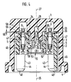
- FIG. 1 and 2 show a first exemplary embodiment of a contact strip designed in accordance with the invention
- FIG. 3 shows a greatly enlarged detail of FIG. 1 with the contact strip partially shown
- FIG. 4 shows a section along the line IV-IV in FIG. 3
- FIG. 5 shows a fuel distributor piece with it arranged fuel injection valves, which are electrically contacted together by a contact strip according to the first exemplary embodiment
- FIG. 6 shows a second exemplary embodiment of a contact strip according to the invention
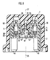
- FIG. 8 a fourth and FIG. 9 a fifth exemplary embodiment of a contact strip according to the invention.
- the contact strip housing which is designed, for example, as a plastic injection molded part, is designated by 1.
- Plug housing 2 are arranged in the contacting strip housing 1, each of which is assigned to an electrically excitable unit and is used to make electrical contact with it.
- a blind hole-shaped receiving opening 3 is provided in the contact strip housing 1 for each connector housing 2, which is open to a strip end face 4.
- first electrically conductive contact elements 5 are arranged, which are electrically conductively connected to electrical conductors 6 arranged in the contacting strip housing 1.
- the electrical conductors 6 are connected to the contact strip housing 1, for example, by at least one support point 7 of the contact strip housing 1 lying between each receiving opening 3, each support point 7 being formed by caulking the material of the contact strip housing 1 by means of ultrasonic welding.
- a connector 10 is also arranged on the contact strip housing 1, to which the individual electrical conductors 6 are connected and via the known control type of an electronic control device, not shown, electrical control signals for the elec tric excitable units can be entered.
- all electrical conductors 6 extend from the connector 10 to the individual connector housings 2 within the contact strip housing 1 and branch off there to the individual first electrically conductive contact elements 5.
- Two guide arms 11 protrude from the strip end face 4 of the contact strip housing 1 at an axial distance from one another.
- mounting bushes 13, 14 are formed in the contact strip illustrated as an exemplary embodiment during manufacture, which are open at least on their side facing the strip end face 4 and z. B. are formed from a metallic material.
- the fastening bushing 13 has a blind hole 17, which is provided with an internal thread 18, while the fastening bushings 14, which are open on both sides, form fastening holes 16 in the contacting strip housing 1 in connection with strip openings 15, which are concentric with the fastening bushings 14, of the contacting strip housing 1.
- FIG. 3 shows a greatly enlarged section of FIG. 1 with the contact strip partially shown and
- FIG. 4 shows a section along the line IV-IV in FIG. 3.
- a stepped holding element 19 which is made of plastic, for example, is used to connect the connector housing 2, which is made of plastic, for example, to the contact strip housing 1 which is made of plastic.
- the connector housing 2 which is made of plastic, for example, to the contact strip housing 1 which is made of plastic.
- This has a graduated one Holding element 19 has a smaller diameter than the head 20 central region 21 and a smaller diameter than the central region 21, for example stepped tip 22.
- the holding element 19 is through a stepped, concentric to a longitudinal axis 25 of the connector housing 2 formed through opening 26 of the connector housing 2 passed through.
- the holding element 19 With its tip 22, the holding element 19 is inserted into a blind hole 28 of a central elevation 29 of a bottom 30 of the contacting strip housing 1, which runs concentrically to a longitudinal axis 27 of the receiving opening 3 of the contacting strip housing 1.
- the holding element 19 is connected, for example by means of ultrasound welding, to the wall of the blind hole 28 in such a way that the holding element 19 lies with a first element shoulder 31 of the central region 21 in the axial direction on an end face 32 of the central elevation 29.
- the middle elevation 29 protrudes in the axial direction facing the respective connector housing 2 through a bottom face 33 of the bottom part 30 of the contact strip housing 1 and has, for example, an annular cross-sectional area.
- the stepped through opening 26 of the plug housing 2 has a first region 34 facing the bottom end face 33 of the bottom 30, a holding shoulder 35 having a reduced clear width and an adjoining second region 36 facing away from the bottom end face 33.
- the bottom end face 33 of the contact strip housing 1 is opposite the plug end faces 39 of the individual connector housing 2.
- the positioning lugs 40 have, for example, the shape of a right angle and have parallel surfaces 43 in the longitudinal direction of the contact strip housing 1 and parallel surfaces 44 perpendicular to this.
- a connecting web 45 is formed, which connects the two positioning lugs 40 lying on one side of the longitudinal axis 41 at their end facing away from the longitudinal axis 41, so that their two parallel surfaces 44 are shorter than the parallel ones running on the other side of the longitudinal axis 41 Surfaces 44 that end open at the end of the connector housing 2.
- the parallel surfaces 44 and thus the positioning lugs 40 are thus designed asymmetrically to one another on different sides of the strip longitudinal axis 41.
- the connector housing 2 has, for example, two stepped plug openings 46 open on both sides, in each of which a first electrically conductive contact element 5 by means of, for. B. two latches 47 formed on the first electrically conductive contact element 5 are secured by snapping with play.
- a radial play 50 is provided between the stepped through opening 26 of the plug housing 2 in the first region 34 facing the bottom face 33 and the circumference of the cylindrical central elevation 29. Furthermore, a radial play 51 between the clear width of the holding shoulder 35 and the central region 21 of the holding element 19 and a radial play 52 between the head 20 of the holding element 19 and the second region 36 of the through opening 26 surrounding the head 20 are provided.
- the connector housing 2 is freely movable relative to the holding element 19 and thus also with respect to the contact strip housing 1 in the radial or horizontal direction perpendicular to its longitudinal axis 25 or the longitudinal axis 27 of the receptacle.
- a damping element 55 is arranged between the bottom end face 33 of the contacting strip housing 1 and the plug end face 39 of the respective plug housing 2.
- the damping element 55 has, for example, the shape of a plate formed from an elastic material such as plastic or rubber.
- An axial play 60 is provided between the damping element 55 and the bottom end face 33 of the contact strip housing 1 or between the damping element 55 and the plug end face 39 of the respective connector housing 2.
- the axial play 60 and the elasticity of the elastic damping element 55 allow a low-force joining of the contact strip, for example onto a fuel distributor piece 62 with fuel injection valves 63 arranged therein, as shown in FIG. 5.
- the fuel distributor piece 62 corresponds essentially to the fuel distributor piece described in DE-OS 37 30 571.
- a fuel injector 63 is arranged in spaced-apart, stepped valve receiving openings 65, which is enclosed by the valve receiving opening 65, which is open at both ends.
- the fuel injection valve 63 is connected to at least one fuel line running in the fuel distributor piece 62.
- the supply and discharge of the fuel into and from the fuel distributor piece 62 takes place by means of, for example, two connecting pieces 68, 69 of the fuel distributor piece 62.
- the system pressure of the fuel in the fuel distributor piece 62 is regulated in a known manner by a pressure regulator 70 arranged on the fuel distributor piece 62.
- the contact strip is connected to the fuel distributor piece 62 in such a way that it covers the valve receiving openings 65 and the fuel injection valves 63 are held therein.
- the guide arms 11 of the contact strip housing 1 serve for easier assembly of the contact strip and fuel distributor piece 62 and engage in mounting openings 72 of the fuel distributor piece 62.
- Concentric to the fastening openings 16 formed in the contact strip housing 1 and open on both sides are opening holes 74 in the fuel distributor piece 62 that are open on both sides , for example by means of fastening bushings 75 arranged in the fuel distributor piece 62.
- a through hole 76 is formed concentrically with the blind hole 17 of the fastening bushing 13 in the fuel distributor piece 62, which thread has an internal thread 18, by means of a through bushing 77.
- the head of a screw 79 bears against an end face 78 of the through bushing 77 facing away from the contacting strip housing 1, which screw is screwed into the internal thread 18 of the blind hole 17 of the contacting strip housing 1 and thus connects the contacting strip and the fuel distributor piece 62 to one another.
- the fuel injection valves 63 directly at a receiving opening for fuel injection valves and connecting pieces and lines for the fuel supply, or on a cylinder head which is likewise designed in this way, and to make electrical contact with the fuel injection valves 63 together with a contact strip according to the invention.
- the connector housings 2 of the contact strip serve for the common electrical contacting of the electrically excitable units, for example the fuel injection valves 63.
- the first electrically conductive contact elements 5 of the connector housings 2 with second electrically conductive contact elements 66 of the fuel injection valves 63 are through Plug electrically connected.
- the plug housing 2 can be moved freely relative to the contact strip housing 1 before the joining process, which is made possible by the radial play 50, 51, 52 and the axial play 60 as well as the elasticity of the damping element 55.
- the elastic damping element 55 is between the bottom end face 33 of the contact strip housing 1 and the Connector end face 39 of the respective connector housing 2 clamped and elastically deformed so that the damping element 55 is under mechanical pretension in the direction of the connector longitudinal axis 25.
- the elastic damping element 55 thus clamped between the contact strip housing 1 and the respective plug housing counteracts an internal movement of the plug housing 2 produced by the operation of the internal combustion engine with respect to the contact strip housing 1 and the electrically excitable units by the damping element 55 being elastically deformed.
- the damping element 55 is clamped between the plug housing 2 and the bottom end face 33 of the contacting strip housing 1 after the joining process of the contacting strip and the fuel distributor piece 62, and the damping element is designed such that the movements of the first, which are excited by vibrations of the internal combustion engine, during operation electrically conductive contact elements 5 and the electrical conductor 6 are damped.
- the elastically deformed damping elements 55 are in direct contact with the circumference of push-through openings 58 which they have, against the first electrically conductive contact elements 5 of the plug housing 2 and the electrical conductors 6 which protrude through the push-through openings 58.
- the additional damping also has an advantageous effect on reduced wear at the contact points between the first electrically conductive contact elements 5 of FIG Plug housing 2 and the second electrically conductive contact elements 66 of the electrically excitable units, for example the fuel injection valves 63.
- FIG. 1 A second exemplary embodiment according to the invention is shown in FIG.
- the same and equivalent parts are identified by the same reference numerals as in Figures 1 to 5.
- a damping element in the form of a plate spring 81 is arranged between the plug end face 39 of the plug housing 2 and the stepped bottom 30 of the contact strip housing 1.
- the plate spring 81 has a flat region 82 pointing radially inward to the circumference of the central elevation 29 and a radially outwardly extending oblique spring region 83 which faces the plug housing 2 in the axial direction, for example with its outer end 84 on the plug face 39 of the plug housing 2 is present. It is also possible that the flat spring 81 rests with its flat region 82 on the plug end face 39 of the plug housing 2 or that the plate spring 81 has a cross-sectional shape other than that shown in FIG.
- the connector housing 2 is free with respect to the holding element 19 and thus also with respect to the contact strip housing 1 both in the radial or horizontal direction and perpendicularly thereto movable, so that when connecting the contact strip to the electrically excitable units due to shape and position tolerances, offsets occurring between the first electrically conductive contact elements 5 of the connector housing 2 and the second electrically conductive contact elements 66 of the electrically excitable units are compensated for and damage is avoided.
- the plate spring 81 After the joining process of the contact strip, for example on the fuel distributor piece 62, the plate spring 81 is elastically deformed by the contact with the bottom face 33 and the connector face 39 and is therefore under mechanical tension in the axial direction.
- the elastic deformability of the plate spring 81 enables the effective damping of the internal movements of the plug housing 2 produced by the operation of the internal combustion engine relative to the contact strip housing 1 and the electrically excitable units, and thus the reduction in contact point wear on the first electrically conductive contact elements 5 of the plug housing 2 and the second electrically conductive contact elements 66 of the electrically excitable units.
- FIG. 7 shows a third exemplary embodiment according to the invention, in which the same and equivalent parts have the same reference numerals as in FIGS. 1 to 6.
- the middle elevation 29 of the contacting strip housing 1 faces a plate spring-shaped or tongue-shaped damping element 89 also molded, which extends in the radial direction inwards towards the longitudinal axis 25 of the plug and is connected on the outside to the holding shoulder 35 of the plug housing 2.
- the plate spring-shaped or tongue-shaped damping element 89 is shaped in the axial direction of the end face 32 of the central elevation 29 and lies, for example, with its inner end 90 against the end face 32.
- the clear width of the damping element 89 at its inner end 90 has a significantly larger diameter than the central region 21 of the holding element 19 fastened in the blind hole 28 of the central elevation 29 be trained.
- an axial play 60 is provided between the bottom end face 33 of the contact strip housing 1 and the plug end face 39 of the plug housing 2 in the direction of the longitudinal axis 25 of the plug.
- the contact strip according to the third exemplary embodiment also allows the connector housing 2 to move freely relative to the contact strip housing 1 in the horizontal direction, ie perpendicular to the longitudinal axis 25 of the plug or the longitudinal axis 27 of the receptacle.
- the plate-spring-shaped or tongue-shaped damping element 89 which cooperates with the end face 32 of the central elevation 29 and is elastically deformed in the axial direction after the joining process, dampens, due to its elastic deformability, the inherent movements of the respective plug housing 2 produced by the operation of the internal combustion engine relative to the contact strip housing 1 in particular in the direction of the longitudinal axis 25 of the plug or the longitudinal axis 27 of the receptacle, thus reducing the wear on the contact points on the first electrically conductive contact elements 5 of the plug housing 2 and the second electrically conductive contact elements 66 of the electrically excitable units.
- the damping element 89 can of course also be designed as a plate made of elastic material as in the first exemplary embodiment according to FIGS. 1 to 6 or as a plate spring as in the second exemplary embodiment according to FIG. 6.
- FIG. 8 A fourth exemplary embodiment according to the invention is shown in FIG. 8, the same and equivalent parts being identified with the same reference numerals as in FIGS. 1 to 7.
- the longitudinal axis 25 of the plug or the longitudinal axis of the receptacle are shown 27 an axial play 60 between the respective plug housing 2 and the bottom end face 33 of the contacting strip housing 1 and perpendicular to it radial games 50, 51, 52 between the stepped through opening 26 of the connector housing 2 and the circumference of the cylindrical central elevation 29 or the holding element 19 are provided.
- a, for example, metal disc spring 97 serving as a damping element.
- the plate spring 81 lies, for example, on the second contact surface 96 of the holding shoulder 35 with play relative to the second region 26 and its inner end 90 encompasses the middle region 21 on the first contact surface 95 of the head 20.
- the plate spring 97 rests with its outer end 98 on the first contact surface 95 of the head 20 and with its inner end 91 on the second contact surface 96 of the holding shoulder 35.
- the connector housing 2 and the bottom 30 of the contact strip housing 1 are designed such that after the joining process of the contact strip, for example on a fuel distributor piece 62, the plate spring 97 is clamped elastically deformed in the direction of the longitudinal axis 25 of the plug between the first contact surface 95 and the second contact surface 96.
- the elastic deformability of the plate spring 97 serving as a damping element the inherent movements of the respective plug housing 2 produced by the operation of the internal combustion engine relative to the contact strip housing 1 are damped in particular in the direction of the longitudinal axis 25 of the plug or the longitudinal axis 27 of the receptacle, and thus the contact point wear on the first electrically conductive contact elements 5 the connector housing 2 and on the second electrically conductive contact elements 66 of the electrically excitable units are reduced.
- the damping element 97 can of course also be formed as a plate made of elastic material as in the first embodiment according to FIGS. 1 to 6 or as a plate spring-shaped or tongue-shaped damping element formed on the holding shoulder 35 in accordance with the third exemplary embodiment according to FIG.
- FIG. 9 shows a further, fifth exemplary embodiment according to the invention.
- the same and equivalent parts are provided with the same reference numerals as in Figures 1 to 8.
- radial games 50, 51, 52 between the stepped through opening 26 of the connector housing 2 and the circumference of the cylindrical central elevation 29 of the contact strip housing 1 or the holding element 19 is provided to ensure free movement of the connector housing 2 relative to the contact strip housing 1.
- the damping element 100 can be designed as at least two individual tongues or annular like a plate spring.
- the oblique spring region 102 of the plate-shaped or tongue-shaped damping element 100 extends from the inner end 101 to its outer end 103 in the axial direction facing the bottom end face 33 of the contact strip housing 1.
- An axial play 60 is provided between the outer end 103 of the damping element 100 and the bottom end face 33 of the contact strip housing 1, which ensures that the respective plug housing 2 can move freely relative to the contact strip housing 1.
- the axial clearance 60 is so large and the connector housing 2 or the bottom 30 of the contact strip housing 1 is designed such that after the assembly process of the electrically excitable units and the contact strip, the respective damping element 100, which is also molded onto the connector housing 2, on the bottom end face 33 of the contact strip housing 1 rests directly and is slightly deformed elastically. If the connector housing 2 carries out natural vibrations as a result of the operation of the internal combustion engine, these natural vibrations are damped by the deformability of the damping element 100 and thus the wear on the contact points between the first electrically conductive contact elements 5 of the connector housing 2 and the second electrically conductive contact elements 66 of the electrically excitable units is reduced.
- the respective plate-shaped or tongue-shaped damping elements 100 may be molded onto the bottom end face 33 of the contact strip housing 1 and to cooperate with the corresponding plug end faces 39 of the plug housing 2.
Landscapes
- Engineering & Computer Science (AREA)
- Chemical & Material Sciences (AREA)
- Combustion & Propulsion (AREA)
- Mechanical Engineering (AREA)
- General Engineering & Computer Science (AREA)
- Fuel-Injection Apparatus (AREA)
- Details Of Connecting Devices For Male And Female Coupling (AREA)
- Contacts (AREA)
Claims (11)
- Bande de contact pour la mise commune électrique en contact de plusieurs agrégats, pouvant être excités électriquement, de moteurs à combustion interne, en particulier de soupapes d'injection de carburant, avec un boîtier de bande de contact (1) et des boîtiers de fiches (2) disposés sur le boîtier de bande de contact (1), boîtiers de fiches qui peuvent être reliées aux seconds éléments de contact électriquement conducteurs de chaque agrégat par enfichage, bande de contact caractérisée en ce que les boîtiers de fiche (2) peuvent être déplacés dans le sens de leurs axes longitudinaux de fiche (25) et perpendiculairement à cela par rapport au boîtier de bande de contact (1) de façon flottante et que dans eux sont disposés des premiers éléments de contact électriquement conducteurs 5 et en ce que respectivement un élément d'amortissement (55; 81; 89; 97; 100) est disposé dans le sens des axes longitudinaux de fiche (25) entre les différents boîtiers de fiche (2) et le boîtier de bande de contact (1).
- Bande de contact selon la revendication 1, caractérisée en ce que les soupapes d'injection de carburant (63) sont disposées dans des ouvertures de réception de soupape (65), constituées à une certaine distance les unes des autres, d'un distributeur de carburant (62) et chaque ouverture de réception (65), entourant une soupape d'injection de carburant, est ouverte aux deux extrémités et est au moins en liaison avec une canalisation de carburant qui s'étend dans le distributeur de carburant (62), auquel est relié la bande de contact de telle sorte que les ouvertures de réception (65) soient recouvertes et que les soupapes d'injection de carburant (63) soient maintenues dedans.
- Bande de contact selon l'une des revendications 1 ou 2, caractérisée en ce qu'entre une face frontale (33) du fond du boîtier de bande de contact (1), tournée vers les boîtiers de fiches (2) et chaque face frontale (39) des différents boîtiers de fiche (2) tournés vers la face frontale de fond (33) il est respectivement disposé, un élément d'amortissement (55; 81; 100).
- Bande de contact selon la revendication 3, caractérisée en ce que sur chacune des faces frontales (39) des différents boîtiers de fiche (2) tournées vers la face frontale (33) du fond du boîtier de bande de contact (1) il est formé un élément d'amortissement (100) en forme de languette.
- Bande de contact selon la revendication 3, caractérisée en ce que sur chacune des faces frontales (39) des différents boîtiers de fiche (2), tournées vers la face frontale (33) du fond du boîtier de bande de contact (1) il est formé un élément d'amortissement en forme de disque.
- Bande de contact selon l'une des revendications 1 ou 2, caractérisée en ce que sur le boîtier de bande de contact (1) il est prévu un nombre de soulèvements centraux (29) correspondant au nombre des boîtiers de fiche (2), soulèvements qui font saillie en étant tournés vers le boîtier de fiche correspondant (2) et en ce que les boîtiers de fiche (2) ont une ouverture de passage (26) à gradins s'étendant concentriquement à l'axe longitudinal correspondant de fiche (25), ouverture dans laquelle est formé respectivement un appendice d'arrêt (35) présentant un jour assez réduit, un élément d'amortissement (89) étant disposé entre chaque appendice d'arrêt (35) et chaque soulèvement central (29).
- Bande de contact selon la revendication 6, caractérisée en ce que sur chaque appendice d'arrêt (35) il est formé un élément d'amortissement (89) en forme de disque, qui coopère avec une face frontale (32) tournée vers l'appendice d'arrêt (35) du soulèvement central (29).
- Bande de contact selon la revendication 6, caractérisée en ce que sur chaque appendice d'arrêt (35) il est formé un élément d'amortissement en forme de disque (89), qui coopère avec une face frontale (32) du soulèvement central (29), tournée vers l'appendice d'arrêt (35).
- Bande de contact selon la revendication 1, caractérisée en ce que les boîtiers de fiches (2) ont une ouverture de passage (26) à gradins s'étendant concentriquement à l'axe longitudinal de fiche correspondant (25), ouverture dans laquelle est formé respectivement un appendice d'arrêt (35) présentant un jour réduit et en ce qu'il est prévu des éléments d'arrêt (19) dont l'un sert à maintenir un boîtier individuel de fiche (2) sur le boîtier de bande de contact (1) et qui ont respectivement une tête (20), une zone centrale (21) et un sommet (22), par lequel les éléments d'arrêt (19) sont disposés dans un alésage de trou borne (28) d'un soulèvement central (29) du boîtier de bande de contact (1) et en ce qu'entre une première surface d'appui (95) de la tête (20) de l'élément d'arrêt (19), tournée vers le soulèvement central (29) et une seconde surface d'appui (96) de l'appendice d'arrêt (35), tournée vers la tête (20) de l'élément d'arrêt (19), on dispose un élément d'amortissement (97).
- Bande de contact selon l'une des revendications 1, 2, 3 ou 9, caractérisée en ce que l'élément d'amortissement (55) est réalisé en une matière élastique.
- Bande de contact selon l'une des revendications 1, 2, 3 ou 9, caractérisée en ce que l'élément d'amortissement est constitué sous la forme d'un ressort à disques (81 à 89; 97).
Applications Claiming Priority (2)
| Application Number | Priority Date | Filing Date | Title |
|---|---|---|---|
| DE4030422A DE4030422A1 (de) | 1990-09-26 | 1990-09-26 | Kontaktierungsleiste zur gemeinsamen elektrischen kontaktierung mehrerer elektrisch erregbarer aggregate von brennkraftmaschinen |
| DE4030422 | 1990-09-26 |
Publications (2)
| Publication Number | Publication Date |
|---|---|
| EP0477520A1 EP0477520A1 (fr) | 1992-04-01 |
| EP0477520B1 true EP0477520B1 (fr) | 1993-11-03 |
Family
ID=6415007
Family Applications (1)
| Application Number | Title | Priority Date | Filing Date |
|---|---|---|---|
| EP91113545A Expired - Lifetime EP0477520B1 (fr) | 1990-09-26 | 1991-08-13 | Bande de contact pour un contact commun d'une pluralité d'aggregats qui sont excités électriquement pour moteurs à moteurs à combustion interne |
Country Status (5)
| Country | Link |
|---|---|
| US (1) | US5131857A (fr) |
| EP (1) | EP0477520B1 (fr) |
| JP (1) | JPH04279756A (fr) |
| DE (2) | DE4030422A1 (fr) |
| ES (1) | ES2046833T3 (fr) |
Cited By (1)
| Publication number | Priority date | Publication date | Assignee | Title |
|---|---|---|---|---|
| US5613867A (en) * | 1994-08-23 | 1997-03-25 | The Whitaker Corporation | Electrical connector with anti-chattering interconnection means |
Families Citing this family (17)
| Publication number | Priority date | Publication date | Assignee | Title |
|---|---|---|---|---|
| DE4109653A1 (de) * | 1991-03-23 | 1992-09-24 | Bosch Gmbh Robert | Kontaktierungsleiste zur gemeinsamen elektrischen kontaktierung mehrerer elektrisch betaetigbarer brennstoffeinspritzventile |
| DE4206370A1 (de) * | 1991-05-17 | 1992-11-19 | Mann & Hummel Filter | Steuerleiste in kunststoffkompaktbauweise |
| DE4118512A1 (de) * | 1991-06-06 | 1992-12-10 | Bosch Gmbh Robert | Elektrisch betaetigbares brennstoffeinspritzventil und verfahren zu dessen elektrischer kontaktierung |
| DE4131537A1 (de) * | 1991-09-21 | 1993-04-01 | Bosch Gmbh Robert | Brennstoffverteiler |
| US5363825A (en) * | 1993-01-27 | 1994-11-15 | Volkswagen Ag | Fuel injection arrangement for an internal combustion engine having a plurality of electric fuel injection valves |
| US5471961A (en) * | 1993-09-02 | 1995-12-05 | Siemens Automotive L.P. | Electrical circuitry of a fuel rail assembly |
| DE4332118A1 (de) * | 1993-09-22 | 1995-03-23 | Bosch Gmbh Robert | Brennstoffeinspritzvorrichtung |
| US5607315A (en) * | 1995-03-02 | 1997-03-04 | Siemens Automotive Corporation | Connector for injector retention and electrical connection to a fuel rail |
| US5568798A (en) * | 1995-06-08 | 1996-10-29 | Siemens Automotive Corporation | Plastic fuel rail having integrated electrical wiring |
| US5526225A (en) * | 1995-06-29 | 1996-06-11 | Wang; Ming-Shan | Receptacle with lamp switch and breaker means |
| US5531202A (en) * | 1995-07-18 | 1996-07-02 | Siemens Automotive Corporation | Fuel rail assembly having internal electrical connectors |
| US5616037A (en) * | 1995-08-04 | 1997-04-01 | Siemens Automotive Corporation | Fuel rail with combined electrical connector and fuel injector retainer |
| DE19734971A1 (de) * | 1997-08-13 | 1999-02-18 | Volkswagen Ag | Verkabelungsmodul |
| US5927614A (en) * | 1997-08-22 | 1999-07-27 | Touvelle; Matthew S. | Modular control valve for a fuel injector having magnetic isolation features |
| DE19739502C1 (de) * | 1997-09-09 | 1998-12-10 | Siemens Ag | Elektrische Anschlußeinheit |
| US6053148A (en) * | 1998-02-21 | 2000-04-25 | Ford Motor Company | Intake manifold for an internal combustion engine |
| US7358625B2 (en) * | 2004-12-14 | 2008-04-15 | Woods Industries, Inc. | Power strip with 12 volt outlet |
Citations (1)
| Publication number | Priority date | Publication date | Assignee | Title |
|---|---|---|---|---|
| WO1991012425A1 (fr) * | 1990-02-09 | 1991-08-22 | Robert Bosch Gmbh | Reglette pour le contact electrique simultane d'une pluralite d'organes a excitation electrique de moteurs a combustion interne |
Family Cites Families (6)
| Publication number | Priority date | Publication date | Assignee | Title |
|---|---|---|---|---|
| US4857003A (en) * | 1987-02-06 | 1989-08-15 | Robert Bosch Gmbh | Apparatus for electrical connection of electromagnetically actuatable fuel injection valves |
| DE3730571C2 (de) * | 1987-09-11 | 1998-07-02 | Bosch Gmbh Robert | Vorrichtung zur Halterung, Kraftstoffversorgung und elektrischen Kontaktierung von elektromagnetisch betätigbaren Kraftstoffeinspritzventilen |
| DE8903551U1 (de) * | 1989-03-21 | 1990-07-26 | Grote & Hartmann Gmbh & Co Kg, 5600 Wuppertal | Kontaktierungsleiste für elektromagnetisch betätigbare Kraftstoffeinspritzventile |
| US4950171A (en) * | 1989-08-11 | 1990-08-21 | Itt Corporation | Fuel injector connector system |
| US5030116A (en) * | 1989-09-04 | 1991-07-09 | Sumitomo Wiring System, Ltd. | Connector block for injectors for internal combustion engine and junction terminal for use with the same connector block |
| US5044338A (en) * | 1990-01-23 | 1991-09-03 | Siemens Automotive L.P. | Fuel rail vibration damper |
-
1990
- 1990-09-26 DE DE4030422A patent/DE4030422A1/de not_active Withdrawn
-
1991
- 1991-08-13 DE DE91113545T patent/DE59100556D1/de not_active Expired - Fee Related
- 1991-08-13 EP EP91113545A patent/EP0477520B1/fr not_active Expired - Lifetime
- 1991-08-13 ES ES199191113545T patent/ES2046833T3/es not_active Expired - Lifetime
- 1991-09-16 US US07/760,664 patent/US5131857A/en not_active Expired - Fee Related
- 1991-09-18 JP JP3237649A patent/JPH04279756A/ja active Pending
Patent Citations (1)
| Publication number | Priority date | Publication date | Assignee | Title |
|---|---|---|---|---|
| WO1991012425A1 (fr) * | 1990-02-09 | 1991-08-22 | Robert Bosch Gmbh | Reglette pour le contact electrique simultane d'une pluralite d'organes a excitation electrique de moteurs a combustion interne |
Cited By (1)
| Publication number | Priority date | Publication date | Assignee | Title |
|---|---|---|---|---|
| US5613867A (en) * | 1994-08-23 | 1997-03-25 | The Whitaker Corporation | Electrical connector with anti-chattering interconnection means |
Also Published As
| Publication number | Publication date |
|---|---|
| EP0477520A1 (fr) | 1992-04-01 |
| US5131857A (en) | 1992-07-21 |
| ES2046833T3 (es) | 1994-02-01 |
| JPH04279756A (ja) | 1992-10-05 |
| DE59100556D1 (de) | 1993-12-09 |
| DE4030422A1 (de) | 1992-04-02 |
Similar Documents
| Publication | Publication Date | Title |
|---|---|---|
| EP0477520B1 (fr) | Bande de contact pour un contact commun d'une pluralité d'aggregats qui sont excités électriquement pour moteurs à moteurs à combustion interne | |
| DE69103553T2 (de) | Zündspule für Verbrennungsmotor. | |
| EP0278229B1 (fr) | Dispositif pour le contact électrique d'injecteurs de carburant à commande électromagnétique | |
| EP1485607B1 (fr) | Element d'etancheite pour l'actionneur piezoelectrique d'une soupape d'injection de carburant | |
| EP0304038B2 (fr) | Unité d'allumage pour moteurs à combustion | |
| DE102004021117A1 (de) | Kraftstoffeinspritzvorrichtung | |
| EP0479959A1 (fr) | Barres de contact assurant une mise en contact electrique commune de plusieurs organes a excitation electrique dans des moteurs a combustion interne | |
| DE10321492A1 (de) | Verbinder mit hervorragender Luftdichtigkeit und AGR-Sensor mit einem solchen Verbinder | |
| EP0469099B1 (fr) | Reglette pour le contact électrique simultane d'une pluralité d'injecteurs de carburant électromagnetiques | |
| EP1673817B1 (fr) | Manchon de reception pour un actionneur piezo-electrique | |
| DE202019104173U1 (de) | Vorrichtung zum Befestigen eines ersten Bauteils an einem zweiten Bauteil | |
| EP0715073B1 (fr) | Systeme d'allumage avec une bobine individuelle pour le montage sur une culasse de cylindre de moteur à combustion interne | |
| DE102004053491B3 (de) | Vorrichtung zur elektrischen Verbindung von Kontaktstiften mit Anschlussstiften eines von der Vorrichtung ausgebildeten Steckverbinders | |
| EP1630408B1 (fr) | Injecteur de carburant pour moteur à combustion interne et procédé de montage de cet injecteur | |
| EP1673534B1 (fr) | Douille de reception pour corps d'actionneur | |
| DE3725980C2 (de) | Vorrichtung zur elektrischen Kontaktierung von elektromagnetisch betätigbaren Kraftstoffeinspritzventilen | |
| EP1672212B1 (fr) | Injecteur de carburant pour moteur à combustion interne | |
| DE102023121058A1 (de) | Modulverbinder mit innenliegender Isolierhülse für ein Batteriemodul, Modulpolanschluss und Verbindungsanordnung | |
| EP1628371B1 (fr) | Dispositif de connection électrique | |
| EP1597779A2 (fr) | Douille de reception pour actionneur piezoelectrique | |
| DE8915736U1 (de) | Elektrische Kontaktvorrichtung | |
| DE9107708U1 (de) | Zündkerze zum Zünden von Kraftstoff-Luft-Gemischen | |
| WO2006058901A1 (fr) | Injecteur de carburant pour moteur a combustion interne | |
| EP0893855A2 (fr) | Connexion de câble pour un élément électromécanique de construction | |
| EP1598910A1 (fr) | Dispositif de connexion entre une bougie d'allumage et une bobine d'allumage |
Legal Events
| Date | Code | Title | Description |
|---|---|---|---|
| PUAI | Public reference made under article 153(3) epc to a published international application that has entered the european phase |
Free format text: ORIGINAL CODE: 0009012 |
|
| AK | Designated contracting states |
Kind code of ref document: A1 Designated state(s): DE ES FR GB IT |
|
| 17P | Request for examination filed |
Effective date: 19920904 |
|
| 17Q | First examination report despatched |
Effective date: 19921120 |
|
| GRAA | (expected) grant |
Free format text: ORIGINAL CODE: 0009210 |
|
| AK | Designated contracting states |
Kind code of ref document: B1 Designated state(s): DE ES FR GB IT |
|
| ET | Fr: translation filed | ||
| REF | Corresponds to: |
Ref document number: 59100556 Country of ref document: DE Date of ref document: 19931209 |
|
| GBT | Gb: translation of ep patent filed (gb section 77(6)(a)/1977) |
Effective date: 19931111 |
|
| ITF | It: translation for a ep patent filed | ||
| REG | Reference to a national code |
Ref country code: ES Ref legal event code: FG2A Ref document number: 2046833 Country of ref document: ES Kind code of ref document: T3 |
|
| PLBE | No opposition filed within time limit |
Free format text: ORIGINAL CODE: 0009261 |
|
| STAA | Information on the status of an ep patent application or granted ep patent |
Free format text: STATUS: NO OPPOSITION FILED WITHIN TIME LIMIT |
|
| 26N | No opposition filed | ||
| ITPR | It: changes in ownership of a european patent |
Owner name: OFF.TA DI LICENZA AL PUBBLICO OFFERTA DI LICENZA |
|
| REG | Reference to a national code |
Ref country code: FR Ref legal event code: D6 |
|
| REG | Reference to a national code |
Ref country code: GB Ref legal event code: 746 Effective date: 19950612 |
|
| PGFP | Annual fee paid to national office [announced via postgrant information from national office to epo] |
Ref country code: GB Payment date: 19970725 Year of fee payment: 7 |
|
| PGFP | Annual fee paid to national office [announced via postgrant information from national office to epo] |
Ref country code: FR Payment date: 19970820 Year of fee payment: 7 |
|
| PGFP | Annual fee paid to national office [announced via postgrant information from national office to epo] |
Ref country code: ES Payment date: 19970828 Year of fee payment: 7 |
|
| PGFP | Annual fee paid to national office [announced via postgrant information from national office to epo] |
Ref country code: DE Payment date: 19971024 Year of fee payment: 7 |
|
| PG25 | Lapsed in a contracting state [announced via postgrant information from national office to epo] |
Ref country code: GB Free format text: LAPSE BECAUSE OF NON-PAYMENT OF DUE FEES Effective date: 19980813 |
|
| PG25 | Lapsed in a contracting state [announced via postgrant information from national office to epo] |
Ref country code: ES Free format text: LAPSE BECAUSE OF THE APPLICANT RENOUNCES Effective date: 19980814 |
|
| GBPC | Gb: european patent ceased through non-payment of renewal fee |
Effective date: 19980813 |
|
| PG25 | Lapsed in a contracting state [announced via postgrant information from national office to epo] |
Ref country code: FR Free format text: LAPSE BECAUSE OF NON-PAYMENT OF DUE FEES Effective date: 19990430 |
|
| PG25 | Lapsed in a contracting state [announced via postgrant information from national office to epo] |
Ref country code: DE Free format text: LAPSE BECAUSE OF NON-PAYMENT OF DUE FEES Effective date: 19990601 |
|
| REG | Reference to a national code |
Ref country code: FR Ref legal event code: ST |
|
| REG | Reference to a national code |
Ref country code: ES Ref legal event code: FD2A Effective date: 20001009 |
|
| PG25 | Lapsed in a contracting state [announced via postgrant information from national office to epo] |
Ref country code: IT Free format text: LAPSE BECAUSE OF NON-PAYMENT OF DUE FEES;WARNING: LAPSES OF ITALIAN PATENTS WITH EFFECTIVE DATE BEFORE 2007 MAY HAVE OCCURRED AT ANY TIME BEFORE 2007. THE CORRECT EFFECTIVE DATE MAY BE DIFFERENT FROM THE ONE RECORDED. Effective date: 20050813 |