EP0715073B1 - Systeme d'allumage avec une bobine individuelle pour le montage sur une culasse de cylindre de moteur à combustion interne - Google Patents
Systeme d'allumage avec une bobine individuelle pour le montage sur une culasse de cylindre de moteur à combustion interne Download PDFInfo
- Publication number
- EP0715073B1 EP0715073B1 EP95118317A EP95118317A EP0715073B1 EP 0715073 B1 EP0715073 B1 EP 0715073B1 EP 95118317 A EP95118317 A EP 95118317A EP 95118317 A EP95118317 A EP 95118317A EP 0715073 B1 EP0715073 B1 EP 0715073B1
- Authority
- EP
- European Patent Office
- Prior art keywords
- spark plug
- plug connector
- cylinder head
- ignition
- combustion engine
- Prior art date
- Legal status (The legal status is an assumption and is not a legal conclusion. Google has not performed a legal analysis and makes no representation as to the accuracy of the status listed.)
- Expired - Lifetime
Links
- 238000002485 combustion reaction Methods 0.000 title claims description 6
- 230000014759 maintenance of location Effects 0.000 claims 1
- 230000000717 retained effect Effects 0.000 claims 1
- 238000004519 manufacturing process Methods 0.000 description 5
- 239000004020 conductor Substances 0.000 description 2
- 238000004804 winding Methods 0.000 description 2
- 238000013016 damping Methods 0.000 description 1
- 239000012777 electrically insulating material Substances 0.000 description 1
- 230000007717 exclusion Effects 0.000 description 1
- 238000003780 insertion Methods 0.000 description 1
- 230000037431 insertion Effects 0.000 description 1
- 239000012212 insulator Substances 0.000 description 1
- 229920001296 polysiloxane Polymers 0.000 description 1
Images
Classifications
-
- H—ELECTRICITY
- H01—ELECTRIC ELEMENTS
- H01T—SPARK GAPS; OVERVOLTAGE ARRESTERS USING SPARK GAPS; SPARKING PLUGS; CORONA DEVICES; GENERATING IONS TO BE INTRODUCED INTO NON-ENCLOSED GASES
- H01T13/00—Sparking plugs
- H01T13/02—Details
- H01T13/06—Covers forming a part of the plug and protecting it against adverse environment
-
- F—MECHANICAL ENGINEERING; LIGHTING; HEATING; WEAPONS; BLASTING
- F02—COMBUSTION ENGINES; HOT-GAS OR COMBUSTION-PRODUCT ENGINE PLANTS
- F02P—IGNITION, OTHER THAN COMPRESSION IGNITION, FOR INTERNAL-COMBUSTION ENGINES; TESTING OF IGNITION TIMING IN COMPRESSION-IGNITION ENGINES
- F02P3/00—Other installations
- F02P3/02—Other installations having inductive energy storage, e.g. arrangements of induction coils
Definitions
- the invention relates to a single coil ignition system with the Features of the preamble of claim 1.
- Known devices of this type consist of screw connections the ignition coil with the cylinder head and are described in DE 39 37 828 C1 and EP 0 454 598 A1.
- the magnetic core of the ignition coil is preferably included provided additional fastening openings through which a fastening screw into the cylinder head is screwed in.
- the preferably two or four Fastening screws require during assembly and disassembly the device a special effort.
- a single coil ignition system is known from EP-A-579487, in which an insulator, a tubular conductor and a spring are successively introduced into the cylinder head. The conductor is locked on its upper side with the voltage exclusion of an ignition coil. The mechanical and electrical connection of the ignition coil to the spark plug requires a lot of assembly work.
- the invention has for its object a device of the type mentioned at the outset, which is due to a low assembly and manufacturing effort characterized by reduced weight.
- the latch of the spark plug connector with the spark plug is indeed long known for spark plug connectors, which have an ignition cable are connected to a central ignition coil. in the The difference is the spark plug connector in the invention usually during assembly not visible and that Reaching the effective position is not recognizable from outside.
- the latching enables mechanical and acoustic to recognize that the single coil ignition system has reached the intended position.
- the latch serves thus also as a mechanical stop for the single coil ignition system and thus as an assembly aid.
- the feature specified in claim 2 is used to the positive connection between the spark plug connector and the ignition coil to increase. At the same time, the possibility remains the axis of the spark plug connector opposite the ignition coil to tilt if this is due to manufacturing tolerances required when attaching the system to the spark plug is.
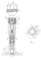
- Fig. 1 shows a single coil ignition system consisting of a Ignition coil 1 with magnetic core 1 'of a primary and secondary winding (not shown) and one Spark plug connector 2.
- the magnetic core 1 ' is via the ground connection the secondary winding is grounded (not shown).
- a spark plug 6 which by the Single coil ignition system is supplied with high voltage.
- the single coil ignition system is via the spark plug connector 2 elastic in a passage opening 7 of the cylinder head 3 held and by a snap connection between a contact part 8 of the spark plug 6 under the spark plug connector 2 axially fixed.
- the rest connection between Spark plug and spark plug connector 2 is known per se Built in this way and consists essentially of Ribbon spring 9 in the spark plug connector 2, which has a paragraph 10 of the contact part 8 engages behind.
- the spark plug connector is on for elastic mounting provided on the outside with four ribs 11, which in run in the axial direction and in Fig. 2 in the Top view are shown.
- the ribs 11 are in one piece with the outer wall 2 'of the spark plug connector 2 and consist like this made of elastic electrically insulating Material, e.g. Silicone.
- spark plug connector 2 Between a high voltage connector pulled down 12 of the ignition coil and this inside and outside surrounding and held therein by means of an interference fit Spark plug connector 2 is an O-ring 13, which is in a Ring groove of the spark plug connector is held. So that will the stiffness of ignition coil 1 and spark plug connector 2 relative to each other while increasing the possibility remains, ignition coil 1 and spark plug connector 2 offset or aligned exactly axially to each other.
- the complete Unit consisting of ignition coil 1 and spark plug connector 2 inserted into the cylinder head. Get there the ribs 11 engage the opening 7 and slide along it until the spark plug connector 2 with the contact part locked. The complete unit is then through the frictional engagement between the ribs 11 and the opening 7 and by locking with the spark plug 6 in the Action held.
- a separate or even exclusive The ignition coil is not attached. Possibly. can by a cover, not shown, which several side by side arranged single coil ignition systems surrounds and the one in the direction of arrow 14 stop has an additional axial fixation of the system be achieved. It is easy to see that the device shown is simple and safe too assemble and at the same time under all occurring dynamic loads during the operation of the Internal combustion engine maintains its active position.
Landscapes
- Engineering & Computer Science (AREA)
- Chemical & Material Sciences (AREA)
- Combustion & Propulsion (AREA)
- Mechanical Engineering (AREA)
- General Engineering & Computer Science (AREA)
- Ignition Installations For Internal Combustion Engines (AREA)
Claims (3)
- Système d'allumage à bobine unique qui se place dans la culasse d'un moteur à combustion interne, ce système se composant d'une bobine d'allumage et d'un connecteur de bougie accroché à celle-ci, dans la direction longitudinale, pour passer dans une cheminée de la culasse et être relié, avec mise en contact, à la pièce de contact de la bougie d'allumage,
le système d'allumage à bobine unique pouvant être tenu dans la culasse (3) par le connecteur de bougie (2) du fait que le connecteur de bougie (2) peut s'appuyer élastiquement dans la cheminée (7) de la culasse (3),
caractérisé en ce quele connecteur de bougie (2) peut également s'accrocher à la pièce de contact (8) de la bougie d'allumage (6), etpour le montage élastique du connecteur de bougie (2), celui-ci comporte, sur son côté extérieur, des nervures (11) qui s'appuient contre la paroi intérieure de la cheminée (7) de la culasse (3), etles nervures (11) sont dirigées dans la direction longitudinale du connecteur de bougie (2). - Dispositif selon la revendication 1,
caractérisé par
un joint torique (13) entre le connecteur de bougie (2) et la bobine d'allumage (1). - Dispositif selon la revendication 1 ou 2,
caractérisé en ce que
le joint torique (13) est logé dans une rainure annulaire du connecteur de bougie (2).
Applications Claiming Priority (2)
| Application Number | Priority Date | Filing Date | Title |
|---|---|---|---|
| DE4442634 | 1994-11-30 | ||
| DE4442634A DE4442634B4 (de) | 1994-11-30 | 1994-11-30 | Vorrichtung zum Befestigen eines Einzelspulenzündsystems mit dem Zylinderkopf einer Brennkraftmaschine |
Publications (3)
| Publication Number | Publication Date |
|---|---|
| EP0715073A2 EP0715073A2 (fr) | 1996-06-05 |
| EP0715073A3 EP0715073A3 (fr) | 1997-08-13 |
| EP0715073B1 true EP0715073B1 (fr) | 2001-10-10 |
Family
ID=6534557
Family Applications (1)
| Application Number | Title | Priority Date | Filing Date |
|---|---|---|---|
| EP95118317A Expired - Lifetime EP0715073B1 (fr) | 1994-11-30 | 1995-11-21 | Systeme d'allumage avec une bobine individuelle pour le montage sur une culasse de cylindre de moteur à combustion interne |
Country Status (3)
| Country | Link |
|---|---|
| EP (1) | EP0715073B1 (fr) |
| DE (2) | DE4442634B4 (fr) |
| ES (1) | ES2164736T3 (fr) |
Cited By (1)
| Publication number | Priority date | Publication date | Assignee | Title |
|---|---|---|---|---|
| US20250257683A1 (en) * | 2022-05-02 | 2025-08-14 | Sem Ab | Tubular structure adapted to at least partly enclose a pencil coil for internal combustion engines |
Families Citing this family (5)
| Publication number | Priority date | Publication date | Assignee | Title |
|---|---|---|---|---|
| DE19831196C2 (de) * | 1998-07-11 | 2002-06-13 | Audi Ag | Zündspuleneinheit für Brennkraftmaschinen |
| DE19851127C2 (de) * | 1998-11-06 | 2003-08-21 | Beru Ag | Zündkerzensteckerstützmanschette |
| DE10058147C2 (de) * | 2000-03-23 | 2003-08-28 | Beru Ag | Verbindungsanordnung von Zündspule und Zündkerze |
| DE10014169C2 (de) * | 2000-11-22 | 2002-09-19 | Beru Ag | Verbindungsanordnung von Zündspule und Zündkerze |
| CN106710851A (zh) * | 2015-11-16 | 2017-05-24 | 联合汽车电子有限公司 | 点火线圈高压接杆 |
Citations (1)
| Publication number | Priority date | Publication date | Assignee | Title |
|---|---|---|---|---|
| EP0579487A2 (fr) * | 1992-07-16 | 1994-01-19 | Sumitomo Wiring Systems, Ltd. | Construction d'un couplage |
Family Cites Families (14)
| Publication number | Priority date | Publication date | Assignee | Title |
|---|---|---|---|---|
| GB2176061B (en) * | 1985-05-23 | 1989-07-19 | Herbert Walker | Internal combustion engine spark plug connector |
| DE3620826A1 (de) * | 1985-06-22 | 1987-01-02 | Pvl Probosch Vogt Loos Gmbh & | Mit einem kerzenstecker integrierte zuendspule |
| DE3544870A1 (de) * | 1985-12-18 | 1987-06-19 | Beru Werk Ruprecht Gmbh Co A | Zuendkerzenstecker |
| EP0344387B1 (fr) * | 1988-05-31 | 1994-11-30 | Société à Responsabilité Limitée L'ELECTRICFIL INDUSTRIE | Bloc transformateur-allumage intégré pour cylindre de moteur thermique à allumage commandé |
| GB8800444D0 (en) * | 1988-01-09 | 1988-02-10 | Lucas Ind Plc | Spark plug connector |
| DE3937828C1 (en) | 1989-11-14 | 1991-06-20 | Bremi Auto-Elektrik Bremicker Gmbh + Co, 5883 Kierspe, De | Ignition coil for IC engine - has two opposite-facing side walls of housing with orifices which serve as entrance for magnetic core |
| FR2655384B1 (fr) * | 1989-12-01 | 1994-05-27 | Peugeot | Dispositif d'amenagement et de maintien dans une culasse de moteur d'un ensemble constitue par une bobine d'allumage et une bougie. |
| FR2655386B1 (fr) * | 1989-12-01 | 1994-06-10 | Peugeot | Dispositif de fixation amovible sur une culasse de moteur d'un ensemble constitue par une bobine d'allumage et une bougie. |
| FR2661216B1 (fr) | 1990-04-23 | 1992-08-14 | Electricfil Ind Sarl | Bobine integree d'allumage individuel d'une bougie de moteur thermique a combustion interne et a allumage commande. |
| JPH04143461A (ja) * | 1990-10-05 | 1992-05-18 | Honda Motor Co Ltd | 内燃機関の点火装置 |
| DE4214816C1 (de) * | 1992-05-05 | 1993-10-21 | Daimler Benz Ag | Zündkerzenstecker für einen Verbrennungsmotor |
| WO1994006183A1 (fr) * | 1992-09-08 | 1994-03-17 | Allied-Signal Inc. | Raccord terminal de bougie d'allumage |
| DE4314780A1 (de) * | 1992-10-02 | 1994-04-07 | Duerrwaechter E Dr Doduco | Zündkerzenstecker |
| EP0590657B1 (fr) * | 1992-10-02 | 1996-05-22 | DODUCO GMBH + Co Dr. Eugen DÀ¼rrwächter | Connecteur de bougie d'allumage |
-
1994
- 1994-11-30 DE DE4442634A patent/DE4442634B4/de not_active Expired - Fee Related
-
1995
- 1995-11-21 DE DE59509681T patent/DE59509681D1/de not_active Expired - Fee Related
- 1995-11-21 EP EP95118317A patent/EP0715073B1/fr not_active Expired - Lifetime
- 1995-11-21 ES ES95118317T patent/ES2164736T3/es not_active Expired - Lifetime
Patent Citations (1)
| Publication number | Priority date | Publication date | Assignee | Title |
|---|---|---|---|---|
| EP0579487A2 (fr) * | 1992-07-16 | 1994-01-19 | Sumitomo Wiring Systems, Ltd. | Construction d'un couplage |
Cited By (1)
| Publication number | Priority date | Publication date | Assignee | Title |
|---|---|---|---|---|
| US20250257683A1 (en) * | 2022-05-02 | 2025-08-14 | Sem Ab | Tubular structure adapted to at least partly enclose a pencil coil for internal combustion engines |
Also Published As
| Publication number | Publication date |
|---|---|
| DE4442634A1 (de) | 1996-06-05 |
| ES2164736T3 (es) | 2002-03-01 |
| DE4442634B4 (de) | 2007-08-30 |
| DE59509681D1 (de) | 2001-11-15 |
| EP0715073A2 (fr) | 1996-06-05 |
| EP0715073A3 (fr) | 1997-08-13 |
Similar Documents
| Publication | Publication Date | Title |
|---|---|---|
| DE3851478T2 (de) | Transformator. | |
| DE69103553T2 (de) | Zündspule für Verbrennungsmotor. | |
| EP0304038B2 (fr) | Unité d'allumage pour moteurs à combustion | |
| DE102005043044B4 (de) | Zündvorrichtung für einen Verbrennungsmotor | |
| EP0477520B1 (fr) | Bande de contact pour un contact commun d'une pluralité d'aggregats qui sont excités électriquement pour moteurs à moteurs à combustion interne | |
| EP2462340A2 (fr) | Bobine, bougie et système d'allumage | |
| DE102019111078A1 (de) | Befestigungsanordnung mit Dämpfungswirkung und Bauteilverbindung mit der Befestigungsanordnung | |
| DE102005030890A1 (de) | Zündvorrichtung für eine Brennkraftmaschine | |
| DE69314710T2 (de) | Kupplungssystem | |
| EP0715073B1 (fr) | Systeme d'allumage avec une bobine individuelle pour le montage sur une culasse de cylindre de moteur à combustion interne | |
| EP1611346B1 (fr) | Bobine d'allumage "crayon" a emboitement | |
| DE19623399C2 (de) | Zündspule für Brennkraftmaschinen | |
| EP0229225B1 (fr) | Dispositif pour mesurer le niveau dans un récipient | |
| EP2324561A1 (fr) | Support anti-vibrations à découplage d'une machine électrique | |
| DE4125347A1 (de) | Bauelement zur uebertragung elektrischer energie | |
| EP4713992A1 (fr) | Connecteur de module pour connexion électrique à une connexion de pôle de module d'un module de batterie, connexion de pôle de module et ensemble de connexion | |
| DE69114944T2 (de) | Verbindung von Zündespule mit einer Zündkerze für innere Brennkraftmaschine mit gesteuerter Zündung. | |
| EP0700815A2 (fr) | Amplificateur de force de freinage à commande électronique et à passage de câble | |
| EP1598910B1 (fr) | Dispositif de connexion entre une bougie d'allumage et une bobine d'allumage | |
| DE3104115A1 (de) | Befestigungsanordnung fuer laeufer von hochspannungsverteilern | |
| EP3523554A1 (fr) | Dispositif de mise en contact pour une soupape pouvant être pilotée électriquement disposée à l'intérieur d'un amortisseur de vibrations | |
| DE10135165C2 (de) | Stabzündspule und Außenblech einer Stabzündspule | |
| DE19857484A1 (de) | Verbindungsstecker | |
| DE29818882U1 (de) | Zündvorrichtung für eine Brennkraftmaschine | |
| DE102023121058A1 (de) | Modulverbinder mit innenliegender Isolierhülse für ein Batteriemodul, Modulpolanschluss und Verbindungsanordnung |
Legal Events
| Date | Code | Title | Description |
|---|---|---|---|
| PUAI | Public reference made under article 153(3) epc to a published international application that has entered the european phase |
Free format text: ORIGINAL CODE: 0009012 |
|
| AK | Designated contracting states |
Kind code of ref document: A2 Designated state(s): DE ES FR GB IT |
|
| PUAL | Search report despatched |
Free format text: ORIGINAL CODE: 0009013 |
|
| RHK1 | Main classification (correction) |
Ipc: H01T 13/04 |
|
| AK | Designated contracting states |
Kind code of ref document: A3 Designated state(s): DE ES FR GB IT |
|
| 17P | Request for examination filed |
Effective date: 19980122 |
|
| 17Q | First examination report despatched |
Effective date: 19980626 |
|
| RTI1 | Title (correction) |
Free format text: IGNITION SYSTEM COMPRISING ONE COIL PER IGNITION PLUG AND FOR MOUNTING IN THE CYLINDER HEAD OF AN INTERNAL COMBUSTION ENGINE |
|
| GRAG | Despatch of communication of intention to grant |
Free format text: ORIGINAL CODE: EPIDOS AGRA |
|
| GRAG | Despatch of communication of intention to grant |
Free format text: ORIGINAL CODE: EPIDOS AGRA |
|
| GRAH | Despatch of communication of intention to grant a patent |
Free format text: ORIGINAL CODE: EPIDOS IGRA |
|
| GRAH | Despatch of communication of intention to grant a patent |
Free format text: ORIGINAL CODE: EPIDOS IGRA |
|
| GRAA | (expected) grant |
Free format text: ORIGINAL CODE: 0009210 |
|
| AK | Designated contracting states |
Kind code of ref document: B1 Designated state(s): DE ES FR GB IT |
|
| REF | Corresponds to: |
Ref document number: 59509681 Country of ref document: DE Date of ref document: 20011115 |
|
| ET | Fr: translation filed | ||
| REG | Reference to a national code |
Ref country code: GB Ref legal event code: IF02 |
|
| GBT | Gb: translation of ep patent filed (gb section 77(6)(a)/1977) |
Effective date: 20011219 |
|
| REG | Reference to a national code |
Ref country code: ES Ref legal event code: FG2A Ref document number: 2164736 Country of ref document: ES Kind code of ref document: T3 |
|
| PLBE | No opposition filed within time limit |
Free format text: ORIGINAL CODE: 0009261 |
|
| STAA | Information on the status of an ep patent application or granted ep patent |
Free format text: STATUS: NO OPPOSITION FILED WITHIN TIME LIMIT |
|
| 26N | No opposition filed | ||
| PGFP | Annual fee paid to national office [announced via postgrant information from national office to epo] |
Ref country code: ES Payment date: 20081030 Year of fee payment: 14 |
|
| PGFP | Annual fee paid to national office [announced via postgrant information from national office to epo] |
Ref country code: IT Payment date: 20081127 Year of fee payment: 14 |
|
| PGFP | Annual fee paid to national office [announced via postgrant information from national office to epo] |
Ref country code: FR Payment date: 20081128 Year of fee payment: 14 |
|
| PGFP | Annual fee paid to national office [announced via postgrant information from national office to epo] |
Ref country code: DE Payment date: 20081211 Year of fee payment: 14 |
|
| PGFP | Annual fee paid to national office [announced via postgrant information from national office to epo] |
Ref country code: GB Payment date: 20081127 Year of fee payment: 14 |
|
| GBPC | Gb: european patent ceased through non-payment of renewal fee |
Effective date: 20091121 |
|
| REG | Reference to a national code |
Ref country code: FR Ref legal event code: ST Effective date: 20100730 |
|
| PG25 | Lapsed in a contracting state [announced via postgrant information from national office to epo] |
Ref country code: FR Free format text: LAPSE BECAUSE OF NON-PAYMENT OF DUE FEES Effective date: 20091130 |
|
| PG25 | Lapsed in a contracting state [announced via postgrant information from national office to epo] |
Ref country code: DE Free format text: LAPSE BECAUSE OF NON-PAYMENT OF DUE FEES Effective date: 20100601 |
|
| PG25 | Lapsed in a contracting state [announced via postgrant information from national office to epo] |
Ref country code: GB Free format text: LAPSE BECAUSE OF NON-PAYMENT OF DUE FEES Effective date: 20091121 |
|
| REG | Reference to a national code |
Ref country code: ES Ref legal event code: FD2A Effective date: 20110329 |
|
| PG25 | Lapsed in a contracting state [announced via postgrant information from national office to epo] |
Ref country code: IT Free format text: LAPSE BECAUSE OF NON-PAYMENT OF DUE FEES Effective date: 20091121 |
|
| PG25 | Lapsed in a contracting state [announced via postgrant information from national office to epo] |
Ref country code: ES Free format text: LAPSE BECAUSE OF NON-PAYMENT OF DUE FEES Effective date: 20110316 |
|
| PG25 | Lapsed in a contracting state [announced via postgrant information from national office to epo] |
Ref country code: ES Free format text: LAPSE BECAUSE OF NON-PAYMENT OF DUE FEES Effective date: 20091122 |