EP0477924B1 - Turbopompe à vide - Google Patents
Turbopompe à vide Download PDFInfo
- Publication number
- EP0477924B1 EP0477924B1 EP91116371A EP91116371A EP0477924B1 EP 0477924 B1 EP0477924 B1 EP 0477924B1 EP 91116371 A EP91116371 A EP 91116371A EP 91116371 A EP91116371 A EP 91116371A EP 0477924 B1 EP0477924 B1 EP 0477924B1
- Authority
- EP
- European Patent Office
- Prior art keywords
- pump
- vacuum pump
- stage
- turbo vacuum
- rotor
- Prior art date
- Legal status (The legal status is an assumption and is not a legal conclusion. Google has not performed a legal analysis and makes no representation as to the accuracy of the status listed.)
- Expired - Lifetime
Links
- 230000002093 peripheral effect Effects 0.000 claims description 25
- 238000005086 pumping Methods 0.000 claims description 7
- 238000001816 cooling Methods 0.000 claims description 2
- 239000003921 oil Substances 0.000 description 5
- 239000010687 lubricating oil Substances 0.000 description 4
- 230000007423 decrease Effects 0.000 description 3
- 239000004519 grease Substances 0.000 description 3
- 238000005192 partition Methods 0.000 description 3
- 230000006835 compression Effects 0.000 description 2
- 238000007906 compression Methods 0.000 description 2
- 238000011109 contamination Methods 0.000 description 2
- 230000001050 lubricating effect Effects 0.000 description 2
- 238000007789 sealing Methods 0.000 description 2
- 230000015572 biosynthetic process Effects 0.000 description 1
- 230000006866 deterioration Effects 0.000 description 1
- 238000000034 method Methods 0.000 description 1
- 238000010926 purge Methods 0.000 description 1
- 230000003068 static effect Effects 0.000 description 1
Images


Classifications
-
- F—MECHANICAL ENGINEERING; LIGHTING; HEATING; WEAPONS; BLASTING
- F04—POSITIVE - DISPLACEMENT MACHINES FOR LIQUIDS; PUMPS FOR LIQUIDS OR ELASTIC FLUIDS
- F04D—NON-POSITIVE-DISPLACEMENT PUMPS
- F04D29/00—Details, component parts, or accessories
- F04D29/05—Shafts or bearings, or assemblies thereof, specially adapted for elastic fluid pumps
- F04D29/056—Bearings
- F04D29/057—Bearings hydrostatic; hydrodynamic
-
- F—MECHANICAL ENGINEERING; LIGHTING; HEATING; WEAPONS; BLASTING
- F04—POSITIVE - DISPLACEMENT MACHINES FOR LIQUIDS; PUMPS FOR LIQUIDS OR ELASTIC FLUIDS
- F04D—NON-POSITIVE-DISPLACEMENT PUMPS
- F04D17/00—Radial-flow pumps, e.g. centrifugal pumps; Helico-centrifugal pumps
- F04D17/08—Centrifugal pumps
- F04D17/16—Centrifugal pumps for displacing without appreciable compression
- F04D17/168—Pumps specially adapted to produce a vacuum
-
- F—MECHANICAL ENGINEERING; LIGHTING; HEATING; WEAPONS; BLASTING
- F04—POSITIVE - DISPLACEMENT MACHINES FOR LIQUIDS; PUMPS FOR LIQUIDS OR ELASTIC FLUIDS
- F04D—NON-POSITIVE-DISPLACEMENT PUMPS
- F04D19/00—Axial-flow pumps
- F04D19/02—Multi-stage pumps
- F04D19/04—Multi-stage pumps specially adapted to the production of a high vacuum, e.g. molecular pumps
-
- F—MECHANICAL ENGINEERING; LIGHTING; HEATING; WEAPONS; BLASTING
- F04—POSITIVE - DISPLACEMENT MACHINES FOR LIQUIDS; PUMPS FOR LIQUIDS OR ELASTIC FLUIDS
- F04D—NON-POSITIVE-DISPLACEMENT PUMPS
- F04D23/00—Other rotary non-positive-displacement pumps
- F04D23/008—Regenerative pumps
-
- F—MECHANICAL ENGINEERING; LIGHTING; HEATING; WEAPONS; BLASTING
- F04—POSITIVE - DISPLACEMENT MACHINES FOR LIQUIDS; PUMPS FOR LIQUIDS OR ELASTIC FLUIDS
- F04D—NON-POSITIVE-DISPLACEMENT PUMPS
- F04D29/00—Details, component parts, or accessories
- F04D29/05—Shafts or bearings, or assemblies thereof, specially adapted for elastic fluid pumps
- F04D29/051—Axial thrust balancing
- F04D29/0513—Axial thrust balancing hydrostatic; hydrodynamic thrust bearings
Definitions
- the present invention relates to a turbo vacuum pump comprising a housing having an inlet port and an outlet port, a cylindrical rotor disposed in the housing and having a stepped peripheral surface and a plurality of blades secured to protruding corners of the steps, a pumping mechanism portion in which a pumping stage is formed by a stator which faces the blades of said rotor across a narrow gap, and in which peripheral pump flow paths are provided in step-like recessions inside the stator, a rotating shaft connected to said rotor and rotatably supported by bearings, and a motor portion for operating said rotor whereby gas drawn in through the inlet port can be discharged into the atmosphere through the outlet port.
- This generic turbo vacuum pump as described in DE-A-3 932 228 is arranged to have an outlet port at an atmospheric pressure and support the rotating shaft of the pump rotor by ball bearings disposed at two positions and lubricated with oil and thus makes it necessary to provide sealing means between the pump part and the driving part so as not to contaminate the vacuum system.
- sealing means a screw seal of the non-contact type or an oil seal of the non-contact type for purging the compressed gas is employed.
- JP-A-2-16389 describes a turbo molecular drag pump which is arranged to dispose a radial hydrodynamic type gas bearing and a thrust hydrodynamic type gas bearing at the lower end of the rotary shaft and form a gas seal above the hydrodynamic type gas bearings to seal the driving part.
- the turbo molecular drag pump cannot perform exhaust function, unless the discharge pressure falls within a pressure range less than 10 ⁇ 2 Torr so that the interior of the pump is kept at a pressure less than the atmospheric pressure (e.g. 10 ⁇ 2 Torr).
- turbo molecular drag pump as employing gas bearings requires a non-contact seal, since the gas bearings cannot serve satisfactorily in this case.
- a centrifugal pump stage and a peripheral pump stage constitute a pumping mechanism portion, and a hydrodynamic type gas bearing supports a rotating shaft.
- a conventional turbo vacuum pump according to JP-A-62-2581186 is equipped with a housing having an inlet port and an outlet port, the housing extending between the inlet port and the outlet port, a rotating shaft rotatably supported with the aid of a bearing in the housing, a centrifugal pump stage and a peripheral pump stage.
- the pump stages of the above two types are disposed one after another in the housing.
- an impeller, a stator plate, another impeller and another stator plate are alternately arranged in the axial direction of the pump. Both of these plates must be divided in half to insert them. Such a structure is complicated, and there is a limit to how small the structure can be made.
- the pump has a vertical axis structure in which lubricating oil is drawn in from an oil tank at the lower end of the pump so as to lubricate the bearing. Owing to this structure, the number of possible directions from which the pump can be installed is limited. Also, because of the use of the oil-lubricating ball bearing, the oil contaminates the inside of a passage in the pump during long-time use thereof, even though this contamination is negligible.
- turbo vacuum pump of the generic kind that is compact in structure and easy to handle.
- turbo vacuum pump of the generic kind in that its bearings consist of a radial gas bearing and a grease-lubricating ball bearing.
- the rotating shaft of the pump rotor is supported by a radial gas bearing and a grease-lubricating ball bearing. More specifically, the load in the radial direction is supported by the radial gas bearing and the grease-lubricating ball bearing and the load in the thrust direction is supported by the grease-lubricating ball bearing.
- the pressure within the pump housing and at the outlet port is the atmospheric pressure so that the gas bearing acts satisfactorily.
- lubricating oil is not used for the driving part at all so that no special seal is necessary.
- the radial gas bearing is a hydrodynamic type gas bearing.
- a means for cooling air is provided in the motor portion.
- a spiral grooved pump stage is disposed on the side of an inhaling opening of a peripheral pump stage.
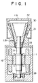
- the turbo vacuum pump shown in Fig. 1 is equipped with a pumping mechanism portion and an operating portion.
- the pumping mechanism portion is composed of a peripheral pump impeller 30, a stator 31 and a lid 32.
- the operating portion is composed of a rotating shaft 13 and a high-frequency motor 16 provided around the rotating shaft 13.
- the rotating shaft 13 is rotatably supported by a hydrodynamic type radial gas bearing 33 and a grease lubricating ball bearing 38, both bearings being accommodated in a housing 11.
- the peripheral pump impeller 30 is shaped as a cylinder having steps. A plurality of blades 35 are secured to protruding corners of the steps. As shown in Figs. 2a and 2b, the stator 31 faces the impeller 30 across a narrow gap therebetween. Around each corner a partition 37 is provided in a portion of a circumferential direction of a gas passage 36 so as to surround the blades 35 of the impeller 30. An inhaling opening 36A is formed at the forward side of each partition 37, and a discharge opening 36B is formed at the rear side of each partition 37, where the peripheral pump impeller 30 rotates.
- the position of the inhaling opening 36A of a given stage deviates from that of another inhaling opening 36A of the next stage; likewise, the position of the discharge opening 36B of a given stage deviates from that of another discharge opening 36B of the next stage.
- the inhaling opening 36A of a given stage is connected in series to the discharge opening 36B of the preceding stage. In this way, because the peripheral pump impeller 30 faces the stator 31 at each stage, these components can be integrally formed with each other.
- the hydrodynamic type radial gas bearing 33 has grooves (not shown) formed on the surface thereof; The hydrodynamic type radial gas bearing 33 supports, in a non-contact manner, the vibrations and load of the rotating shaft 13 in the radial direction of the shaft 13.
- the grease lubricating ball bearing 38 supports the vibrations and load of the rotating shaft 13 in the thrust direction of the shaft 13. Because of the integral formation of the peripheral pump impeller 30 and the stator 31, it is possible to improve the accuracy with which these two components are machined.
- the use of the hydrodynamic type radial gas bearing 33 increases the diameter and hence the stiffness of the rotating shaft 13, thus resulting in an improvement in vibration characteristics.
- the high-frequency motor 16, integrally formed with the rotating shaft 13, is capable of operating the peripheral pump impeller 30 at a high speed.
- the peripheral pump impeller 30 Since the peripheral pump impeller 30 operates at a high speed, gas sucked in through an inlet port 11A flows into the gas passage 36 through the inhaling opening 36A of the first stage.
- the blades 35 rotating at a high speed provide the gas with speed in the circumferential direction of the impeller 30.
- a centrifugal force discharges the gas between the blades 35 in the radial direction of the impeller 30.
- the gas flows again between the blades 35 while forming a vortex.
- the gas undergoes the above procedure as many times as the number of stages while it is flowing through the gas passage 36 from the inhaling opening 36A to the discharge opening 36B of each stage.
- the gas flows helically through the gas passage 36 while fully gaining energy from the peripheral pump impeller 30. It is then discharged into the atmosphere through an outlet port 11B connected to the discharge opening 36B of the last stage.
- the peripheral pump impeller 30 gains a high compression ratio in such a manner that it provides the gas with kinetic energy, which is converted into static pressure. Therefore, if it is possible to rotate the peripheral pump impeller 30 at a high speed, it is also possible to improve the performance of the pump.
- the shaft power of the turbo vacuum pump is proportional to the third power of the rotating speed and the fifth power of the diameter of the impeller.
- a spiral grooved pump stage 41 is provided in addition to a peripheral pump stage 40, composed of the peripheral pump impeller 30 and the stator 31, shown in Fig. 1.
- the peripheral pump stage 40 provides gas with speed energy to convert it into pressure. A high compression ratio is thereby obtainable.
- the performance of the pump can increase in the pressure zone of a viscous flow, but decreases in the pressure zones of intermediate and molecular flows.
- the ultimate pressure of the vacuum pump is limited to a low vacuum zone.
- the spiral grooves pump stage 41 which operates effectively with the intermediate and molecular flows, is installed on the low pressure side of the peripheral pump stage 40.
- a centrifugal pump stage, an axial pump stage or the like is used as a pump stage operating effectively with the intermediate and molecular flows.
- these stages must have a structure in which a stator is divided in half to insert it, so that it is difficult to maintain the accuracy with which the stages are machined.
- the stages are not suitable for a smaller pump operating at a higher speed.
- the ultimate pressure of the turbo vacuum pump can be made higher.
- a fan 39 is provided in a housing 11 in which a hydrodynamic type radial gas bearing 33 and a grease-lubricating ball bearing 38 are accommodated.
- This embodiment can effectively remove the heat generated by a high-frequency motor 16 and the grease-lubricating ball bearing 38. It is thus possible to decrease the deterioration of the grease and to increase the life of the bearings.
Landscapes
- Engineering & Computer Science (AREA)
- Mechanical Engineering (AREA)
- General Engineering & Computer Science (AREA)
- Physics & Mathematics (AREA)
- Fluid Mechanics (AREA)
- Non-Positive Displacement Air Blowers (AREA)
- Structures Of Non-Positive Displacement Pumps (AREA)
Claims (4)
- Turbopompe à vide comprenant- un carter (11) possédant un orifice d'entrée (11A) et un orifice de sortie (11B),- un rotor cylindrique (30) disposé dans le carter (11) et possédant une surface périphérique étagée et une pluralité d'aubes (35) fixées en des coins saillants des parties étagées,- une partie formant mécanisme de pompage, dans lequel un étage de pompage est formé par un stator (31) qui est situé en vis-à-vis des aubes (35) dudit rotor (30) en en étant séparé par un intervalle étroit, et dans lequel des trajets d'écoulement périphériques de pompe sont prévus dans des renfoncements en forme de parties étagées à l'intérieur du stator (31),- un arbre rotatif (13) raccordé audit rotor (30) et supporté, de manière à pouvoir tourner, par des paliers (33,38), et- une partie formant moteur (16) pour entraîner ledit rotor (30),- le gaz introduit par l'orifice d'entrée (11A) pouvant être évacué dans l'atmosphère par l'orifice de sortie (11B),caractérisée en ce que lesdits paliers sont constitués par un palier radial à gaz (33) et un roulement à billes (38) lubrifié par de la graisse.
- Turbopompe à vide selon la revendication 1, dans laquelle le palier radial à gaz (33) est un palier à gaz du type hydrodynamique.
- Turbopompe à vide selon la revendication 1 ou 2, dans laquelle des moyens (39) pour refroidir l'air sont prévus dans la partie formant moteur (16).
- Turbopompe à vide selon l'une des revendications 1 à 3, dans laquelle un étage (41) de la pompe à rainure spirale est disposé sur le côté d'une ouverture d'aspiration (36A) d'un étage de pompe périphérique (40).
Applications Claiming Priority (2)
| Application Number | Priority Date | Filing Date | Title |
|---|---|---|---|
| JP256925/90 | 1990-09-28 | ||
| JP2256925A JP2928615B2 (ja) | 1990-09-28 | 1990-09-28 | ターボ真空ポンプ |
Publications (2)
| Publication Number | Publication Date |
|---|---|
| EP0477924A1 EP0477924A1 (fr) | 1992-04-01 |
| EP0477924B1 true EP0477924B1 (fr) | 1995-05-03 |
Family
ID=17299285
Family Applications (1)
| Application Number | Title | Priority Date | Filing Date |
|---|---|---|---|
| EP91116371A Expired - Lifetime EP0477924B1 (fr) | 1990-09-28 | 1991-09-25 | Turbopompe à vide |
Country Status (4)
| Country | Link |
|---|---|
| US (1) | US5451147A (fr) |
| EP (1) | EP0477924B1 (fr) |
| JP (1) | JP2928615B2 (fr) |
| DE (1) | DE69109424T2 (fr) |
Families Citing this family (9)
| Publication number | Priority date | Publication date | Assignee | Title |
|---|---|---|---|---|
| DE4438812A1 (de) * | 1994-10-31 | 1996-05-02 | Leybold Ag | Reibungsvakuumpumpe mit Kühlung |
| CA2246504C (fr) * | 1996-03-05 | 2005-01-11 | Shell Canada Limited | Stimulation de l'ecoulement descendant dans un puits de gaz naturel |
| JP3010529B1 (ja) * | 1998-08-28 | 2000-02-21 | セイコー精機株式会社 | 真空ポンプ、及び真空装置 |
| DE10048695A1 (de) | 2000-09-30 | 2002-04-11 | Leybold Vakuum Gmbh | Pumpe als Seitenkanalpumpe |
| US7682301B2 (en) | 2003-09-18 | 2010-03-23 | Thoratec Corporation | Rotary blood pump |
| US20070231135A1 (en) | 2006-03-31 | 2007-10-04 | Orqis Medical Corporation | Rotary Blood Pump |
| US10641282B2 (en) * | 2016-12-28 | 2020-05-05 | Nidec Corporation | Fan device and vacuum cleaner including the same |
| JP7463150B2 (ja) * | 2020-03-19 | 2024-04-08 | エドワーズ株式会社 | 真空ポンプ及び真空ポンプ用部品 |
| WO2023137526A1 (fr) * | 2022-01-22 | 2023-07-27 | Nihill Jack | Moteur thermique |
Family Cites Families (11)
| Publication number | Priority date | Publication date | Assignee | Title |
|---|---|---|---|---|
| DE2138152C3 (de) * | 1971-07-30 | 1974-05-09 | W.C. Heraeus Gmbh, 6450 Hanau | Lageranordnung für den Läufer einer Turbomolekularpumpe |
| BE790969A (fr) * | 1971-11-16 | 1973-05-07 | Cit Alcatel | Pivot pour pompes moleculaires rotatives |
| FR2224009A5 (fr) * | 1973-03-30 | 1974-10-25 | Cit Alcatel | |
| DE2359456A1 (de) * | 1973-11-29 | 1975-06-05 | Leybold Heraeus Gmbh & Co Kg | Turbomolekularvakuumpumpe mit gasgelagertem rotor |
| US4180370A (en) * | 1975-03-22 | 1979-12-25 | Kernforschungsanlage Julich Gesellschaft Mit Beschrankter Haftung | Turbomolecular pump |
| JPS62153597A (ja) * | 1985-12-27 | 1987-07-08 | Hitachi Ltd | 真空ポンプ |
| CH672666A5 (fr) * | 1986-11-27 | 1989-12-15 | Bbc Brown Boveri & Cie | |
| DE3728154C2 (de) * | 1987-08-24 | 1996-04-18 | Balzers Pfeiffer Gmbh | Mehrstufige Molekularpumpe |
| FI895719A7 (fi) * | 1988-03-30 | 1989-11-29 | Sholokhov Valery B | Turbomolekyläärinen tyhjöpumppu |
| FR2634829B1 (fr) * | 1988-07-27 | 1990-09-14 | Cit Alcatel | Pompe a vide |
| US5020969A (en) * | 1988-09-28 | 1991-06-04 | Hitachi, Ltd. | Turbo vacuum pump |
-
1990
- 1990-09-28 JP JP2256925A patent/JP2928615B2/ja not_active Expired - Lifetime
-
1991
- 1991-09-25 EP EP91116371A patent/EP0477924B1/fr not_active Expired - Lifetime
- 1991-09-25 DE DE69109424T patent/DE69109424T2/de not_active Expired - Fee Related
- 1991-09-30 US US07/767,666 patent/US5451147A/en not_active Expired - Lifetime
Also Published As
| Publication number | Publication date |
|---|---|
| JP2928615B2 (ja) | 1999-08-03 |
| EP0477924A1 (fr) | 1992-04-01 |
| US5451147A (en) | 1995-09-19 |
| JPH04136497A (ja) | 1992-05-11 |
| DE69109424D1 (de) | 1995-06-08 |
| DE69109424T2 (de) | 1995-09-07 |
Similar Documents
| Publication | Publication Date | Title |
|---|---|---|
| EP0568069B1 (fr) | Pompes à vide turbomoléculaires | |
| EP3938668B1 (fr) | Ensemble palier à feuilles et compresseur le comprenant | |
| EP3401549B1 (fr) | Turbocompresseur | |
| CN1646806A (zh) | 具有转换磁阻电机驱动的离心泵 | |
| EP0477924B1 (fr) | Turbopompe à vide | |
| US6409468B1 (en) | Turbo-molecular pump | |
| JP2741863B2 (ja) | ターボ真空ポンプ | |
| JP2000283085A (ja) | インバーテッドモータ付き真空ポンプ | |
| JP2006509952A (ja) | 真空ポンプ排出装置 | |
| JP7670752B2 (ja) | 可変のホルベック幾何形状を有するホルベックポンプ段を備える真空ポンプ | |
| US6561755B1 (en) | Turbomolecular pump | |
| US7896625B2 (en) | Vacuum pumping system and method of operating a vacuum pumping arrangement | |
| JPH11294358A (ja) | 複軸真空ポンプ | |
| JP7787241B2 (ja) | コンパクトな構造を有するターボ分子真空ポンプ | |
| JP7534466B2 (ja) | ホルベックポンプ段の吸引能力が改善された真空ポンプ | |
| JPH02264196A (ja) | ターボ真空ポンプ | |
| JP2628351B2 (ja) | 複合分子ポンプ | |
| JPH0631198Y2 (ja) | 無漏洩ポンプの軸受装置 | |
| JPH0278793A (ja) | 多段渦流型真空ポンプ | |
| JP2001221187A (ja) | ターボ形ドライポンプ | |
| JPH07217586A (ja) | ターボ真空ポンプ | |
| JPH01393A (ja) | 真空ポンプ装置 | |
| JP2025138558A (ja) | ターボ分子真空ポンプ | |
| JPH05133386A (ja) | ターボ真空ポンプ | |
| JPS58197497A (ja) | タ−ボ分子ポンプ |
Legal Events
| Date | Code | Title | Description |
|---|---|---|---|
| PUAI | Public reference made under article 153(3) epc to a published international application that has entered the european phase |
Free format text: ORIGINAL CODE: 0009012 |
|
| 17P | Request for examination filed |
Effective date: 19910925 |
|
| AK | Designated contracting states |
Kind code of ref document: A1 Designated state(s): DE GB |
|
| 17Q | First examination report despatched |
Effective date: 19930927 |
|
| GRAA | (expected) grant |
Free format text: ORIGINAL CODE: 0009210 |
|
| AK | Designated contracting states |
Kind code of ref document: B1 Designated state(s): DE GB |
|
| REF | Corresponds to: |
Ref document number: 69109424 Country of ref document: DE Date of ref document: 19950608 |
|
| PLBE | No opposition filed within time limit |
Free format text: ORIGINAL CODE: 0009261 |
|
| STAA | Information on the status of an ep patent application or granted ep patent |
Free format text: STATUS: NO OPPOSITION FILED WITHIN TIME LIMIT |
|
| 26N | No opposition filed | ||
| REG | Reference to a national code |
Ref country code: GB Ref legal event code: IF02 |
|
| PGFP | Annual fee paid to national office [announced via postgrant information from national office to epo] |
Ref country code: GB Payment date: 20020913 Year of fee payment: 12 |
|
| PGFP | Annual fee paid to national office [announced via postgrant information from national office to epo] |
Ref country code: DE Payment date: 20021128 Year of fee payment: 12 |
|
| PG25 | Lapsed in a contracting state [announced via postgrant information from national office to epo] |
Ref country code: GB Free format text: LAPSE BECAUSE OF NON-PAYMENT OF DUE FEES Effective date: 20030925 |
|
| PG25 | Lapsed in a contracting state [announced via postgrant information from national office to epo] |
Ref country code: DE Free format text: LAPSE BECAUSE OF NON-PAYMENT OF DUE FEES Effective date: 20040401 |
|
| GBPC | Gb: european patent ceased through non-payment of renewal fee |
Effective date: 20030925 |