EP0478460B1 - Alveolarstecker mit mindestens einer optischen Steckverbindung - Google Patents
Alveolarstecker mit mindestens einer optischen Steckverbindung Download PDFInfo
- Publication number
- EP0478460B1 EP0478460B1 EP91402585A EP91402585A EP0478460B1 EP 0478460 B1 EP0478460 B1 EP 0478460B1 EP 91402585 A EP91402585 A EP 91402585A EP 91402585 A EP91402585 A EP 91402585A EP 0478460 B1 EP0478460 B1 EP 0478460B1
- Authority
- EP
- European Patent Office
- Prior art keywords
- contact
- ring
- male
- mobile
- connector
- Prior art date
- Legal status (The legal status is an assumption and is not a legal conclusion. Google has not performed a legal analysis and makes no representation as to the accuracy of the status listed.)
- Expired - Lifetime
Links
Images

Classifications
-
- G—PHYSICS
- G02—OPTICS
- G02B—OPTICAL ELEMENTS, SYSTEMS OR APPARATUS
- G02B6/00—Light guides; Structural details of arrangements comprising light guides and other optical elements, e.g. couplings
- G02B6/24—Coupling light guides
- G02B6/36—Mechanical coupling means
- G02B6/38—Mechanical coupling means having fibre to fibre mating means
- G02B6/3807—Dismountable connectors, i.e. comprising plugs
- G02B6/3897—Connectors fixed to housings, casing, frames or circuit boards
-
- G—PHYSICS
- G02—OPTICS
- G02B—OPTICAL ELEMENTS, SYSTEMS OR APPARATUS
- G02B6/00—Light guides; Structural details of arrangements comprising light guides and other optical elements, e.g. couplings
- G02B6/24—Coupling light guides
- G02B6/36—Mechanical coupling means
- G02B6/38—Mechanical coupling means having fibre to fibre mating means
- G02B6/3807—Dismountable connectors, i.e. comprising plugs
- G02B6/381—Dismountable connectors, i.e. comprising plugs of the ferrule type, e.g. fibre ends embedded in ferrules, connecting a pair of fibres
- G02B6/3818—Dismountable connectors, i.e. comprising plugs of the ferrule type, e.g. fibre ends embedded in ferrules, connecting a pair of fibres of a low-reflection-loss type
- G02B6/3821—Dismountable connectors, i.e. comprising plugs of the ferrule type, e.g. fibre ends embedded in ferrules, connecting a pair of fibres of a low-reflection-loss type with axial spring biasing or loading means
-
- G—PHYSICS
- G02—OPTICS
- G02B—OPTICAL ELEMENTS, SYSTEMS OR APPARATUS
- G02B6/00—Light guides; Structural details of arrangements comprising light guides and other optical elements, e.g. couplings
- G02B6/24—Coupling light guides
- G02B6/36—Mechanical coupling means
- G02B6/38—Mechanical coupling means having fibre to fibre mating means
- G02B6/3807—Dismountable connectors, i.e. comprising plugs
- G02B6/3873—Connectors using guide surfaces for aligning ferrule ends, e.g. tubes, sleeves, V-grooves, rods, pins, balls
- G02B6/3882—Connectors using guide surfaces for aligning ferrule ends, e.g. tubes, sleeves, V-grooves, rods, pins, balls using rods, pins or balls to align a pair of ferrule ends
-
- G—PHYSICS
- G02—OPTICS
- G02B—OPTICAL ELEMENTS, SYSTEMS OR APPARATUS
- G02B6/00—Light guides; Structural details of arrangements comprising light guides and other optical elements, e.g. couplings
- G02B6/24—Coupling light guides
- G02B6/36—Mechanical coupling means
- G02B6/38—Mechanical coupling means having fibre to fibre mating means
- G02B6/3807—Dismountable connectors, i.e. comprising plugs
- G02B6/3833—Details of mounting fibres in ferrules; Assembly methods; Manufacture
- G02B6/3851—Ferrules having keying or coding means
Definitions
- the present invention relates to a cellular connector, comprising a male connector element and a female connector element having bodies provided with aligned cells adapted to receive at least one fiber optic connection device formed by a male contact and d 'a cooperating female contact.
- Such connectors are used to connect cables or tracks of a printed circuit board, called daughter board, to tracks of another printed circuit board called mother board.
- a male type multicontact cellular connector element is mounted on the daughter board and a corresponding female element is mounted on the mother board.
- Such connectors for printed circuit cards include cells intended to receive different types of contacts and in particular cells intended to receive coaxial contacts.
- Examples of such connectors are provided by the series of connectors according to DIN 41612, or by DE-U-90 05 904.
- the optical contacts in particular the contacts for single-mode optical fibers must have very good axial and angular guidance if one wishes to obtain a weak weakening of the connection.
- the cells of these connector elements as well as their position in the insulating bodies of the connector elements have tolerances incompatible with the guides requested from the optical contacts. These tolerances have in fact been defined for coaxial connectors which require less guiding precision than for fiber optic connections.
- the tolerances for coaxial contacts defined, in particular in standard DIN 41612, are such that the cells of the male and female connector elements (socket and plug of the connectors for printed boards) are not sufficiently well aligned, owing to eccentricities, for a well-guided coupling of optical contacts placed in the cells of these connector elements.
- the present invention proposes to produce a cellular connector making it possible to receive, in aligned cells, connector elements, at least one device for connecting optical fibers with good axial and angular guidance despite the eccentricities of the cells.
- the characteristics of the connector according to the present invention are the subject of claim 1.
- the bearing surfaces facing the ring and the movable optical contact thus constitute pre-guiding means allowing the movable optical contact to be centered with respect to its socket in the disconnected position.
- the mobile optical contact is the male contact of the fiber optic connection device, and elastic means are provided to push the male optical contact towards its connection position.
- these elastic means may consist of a compression spring mounted between the front end of the ring and a bearing surface of the movable male optical contact, the displacement of the movable male contact with respect to the ring during connection taking place against the force of this spring, and said spring pushing back, in the connection position, the male contact in the direction of the female contact.
- the movable contact comprises on its external surface at least two cylindrical bearing surfaces of different diameters, the ring comprising a bearing being substantially in abutment against a bearing of the movable contact in the disconnected position, and opposite and spaced apart from play by another bearing of smaller diameter of said contact in the disconnected position.
- the contact has two ranges of different diameters against which substantially support two bearing surfaces of different diameters of the ring in the disconnected position.
- the ring and the contact have conical surfaces in mutual support in the disconnected position.
- positioning means are provided. angle of the movable optical contact with respect to the card on which is mounted the cellular connector element housing said movable optical contact.
- these angular positioning means consist of a finger projecting radially from the ring while engaging in a radial notch of a cylindrical hole formed in the corresponding card for the passage of the contact, said ring further comprising a key housed in a longitudinal groove of the movable contact.
- optical fiber connection devices capable of being used in the context of the invention can be of any suitable type and in particular of the type described by the applicant company in EP-A-0063085.
- the male optical contact mounted at the end of a fiber optic cable comprises an end piece having an axial tubular protuberance, and set back from the protuberance and surrounding the rear part thereof, an annular recess whose wall has for example a conical profile.
- the female optical contact comprises a female reconstitution connector having in its central part, inside a longitudinal bore, a stop body, in particular a sphere, having an axial through hole and, around it, bearing surfaces contact for on one side the end of the male contact and on the other side for the male end mounted at the end of the other fiber optic cable to be connected and previously engaged in the female reconstitution fitting.
- the female optical contact thus comprises, on the one hand the female reconstitution connector and on the other hand, the second male connector.
- the bearing surfaces facing the abutment body and the male end caps are arranged in such a way that during any relative movement of the bearing surfaces in contact, the end of a fiber at the level of the end face of the protuberance of a mouthpiece male is kept at a predetermined constant distance from the center of the abutment body.
- the end faces of the protrusions of the end pieces and of the fibers immobilized inside are straight, that is to say perpendicular to the longitudinal axis of the connection device but can be inclined relative to this axis when a function mitigation is sought as described for example in French patent application FR-A-2,598,820 of the applicant company.
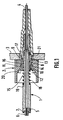
- This figure represents in section a male optical contact generally designated by 1 mounted in a cell of the insulating body of a female cellular connector element designated by 2 and mounted on a printed circuit motherboard 3.
- Contact 1 is mounted at the end of a fiber optic cable 4, for example of the single-mode type, and comprises at its front end a tip 5 having an axial protuberance 6 at the end of which is the end of the optical fiber, and set back from said protuberance a conical bearing 7.
- a ring 8 is provided which is retained axially in the socket of the plug 2, and mounted with a small radial clearance therein.
- the ring 8 has at its rear end a flange 9 engaging behind the rear end face of the plug 2 and a groove 10 in which is housed a split washer 11 having a conical outer surface projecting towards the rear pressing against one of the annular bearing surfaces of the ring 8 defining the groove 10 and an annular bearing surface of the plug 2.
- the ring has two cylindrical surfaces 12, 13 axially spaced and of different diameters, separated by a cylindrical surface of intermediate diameter 14.
- the external surface of the male contact 1 also has several successive cylindrical bearings of different diameters, namely a bearing of reduced diameter 15, a bearing of intermediate diameter 16 and a bearing of larger diameter 17.
- the male contact 1 is provided with the ring 8, the arrangement being such that the surfaces of the external surface of the contact are substantially in abutment against the surfaces of the internal surface of the ring, the term "substantially in support” signifying that there is a very small radial clearance between these bearing surfaces.
- the bearing surface 12 of the ring is substantially in support of the bearing surface 16 of the contact and in the same way, the bearing surface 13 of the ring is substantially in bearing of the bearing surface 17 of the contact.
- the male contact 1 is axially movable relative to the ring 8, which is fixed in the cell, a return spring 18 mounted around the contact and bearing against a bearing surface 19 of the contact and the front end face 20 of the ring 8 being provided to return the contact to the disconnection position of the Figure 1 from the connection position illustrated in Figure 2 which will be described below.
- the longitudinal axial displacement of the contact relative to the ring is limited by an abutment flange 21 produced on the contact and bearing against the flange 9 at the rear of the ring.
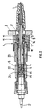
- FIG. 2 illustrates the connector according to the invention in the connection position, a female optical contact generally designated by 22 and housed in a male connector element 23 being connected to the male contact element 1.
- the female optical contact 22 comprises a female reconstitution connector 24 with a hollow spherical abutment body 25 and a male connector 26 similar to the male connector 5 and mounted at the end of a ferrule fixed to the fiber optic cable 27 to connect to cable 4.
- the spring 18 pushes back the male optical contact 1 in the direction of the female contact, so as to elastically push the end piece 5 against the stop body 25.
- the bearing surface 12 of the ring is thus opposite and at a distance from the smaller diameter bearing surface 15 of the contact and the bearing surface 13 of the ring is located opposite and at a distance from the bearing surface 16 of the contact.
- This radial clearance makes it possible to accept the eccentricities of the cells of the connector elements 2 and 23.
- the contact surface 17 may have the same diameter as the contact surface 16 thereof, and the contact surfaces 13 and 14 of the ring of the same diameter as the contact surface 12 thereof.
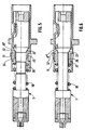
- FIG. 3 differs from that of FIG. 1 in that it is provided with means for angular positioning of the movable male optical contact 1 on the card 3.
- the cylindrical hole drilled in the card for the passage of the contact comprises a notch 28 receiving with play a radial finger 29 of the ring 8 '.
- the ring 8 'further comprises a key 30 housed in a groove 31 of the contact.
- the ring 8 ⁇ has on its internal surface a conical surface 32 bearing in the disconnected position against a conical surface 33 of the external surface of the contact 1.
- the angle ⁇ of the conical surfaces 32 and 33 with the contact axis is preferably between 10 and 20 ° and advantageously 15 °.
- the ring 8 ⁇ has a cylindrical bearing surface 34 which, like the cylindrical bearing surface 12 of the embodiment of FIGS. 1 and 2, is substantially supported in the position of disconnection of a cylindrical bearing surface 35 from the contact which comprises an adjacent bearing surface 36 of smaller diameter.
- the ranges 35 and 36 correspond to the ranges 16 and respectively 15 of the embodiment of FIGS. 1 and 2.
- FIG. 6 differs from that of FIG. 5 in that the ring 8 ′′′ has a cylindrical surface 37 spaced apart with radial clearance in the position of disconnection of the cylindrical surface 38 of the contact.
- the conical bearing surfaces 32 and 33 provide the pre-guidance function according to the invention.
Landscapes
- Physics & Mathematics (AREA)
- General Physics & Mathematics (AREA)
- Optics & Photonics (AREA)
- Mechanical Coupling Of Light Guides (AREA)
- Optical Couplings Of Light Guides (AREA)
- Details Of Connecting Devices For Male And Female Coupling (AREA)
Claims (9)
- Zellenförmiger Verbinder mit einem steckerförmigen Kupplungselement (23) und einem buchsenförmigen Kupplungselement (2), die Körper bilden, die mit ausgerichteten Zellen versehen sind, die dazu ausgebildet sind, wenigstens eine faseroptische Steckverbindung aufzunehmen, die gebildet wird durch einen steckerförmigen Kontakt (1) und einen damit zusammenwirkenden buchsenförmigen Kontakt (22), die dazu ausgebildet sind, jeder in eine Zelle eines der Kupplungselemente einzugreifen, wobei einer der Kontakte (22) fest in seiner Zelle montiert ist und der andere (1) in seiner Zelle axial zwischen einer Trennposition und einer Verbindungsposition der faseroptischen Steckverbindung beweglich montiert ist, dadurch gekennzeichnet, daß er einen Ring (8; 8′; 8˝; 8‴) aufweist, der den beweglichen Kontakt (1) umgibt und in der Zelle montiert und in Axialrichtung fixiert ist, wobei der bewegliche Kontakt und der Ring auf ihren jeweiligen einander zugewandten Oberflächen konische und/oder zylindrische Bereiche mit verschiedenen Durchmessern aufweisen, die so ausgebildet und angeordnet sind, daß in der Trennposition und vorzugsweise auch während eines Teils der Bewegung des beweglichen Kontakts im Laufe der Vorgänge des Herstellens und Trennens der Verbindung wenigstens ein Bereich (12, 13; 32, 34; 32) des Ringes im wesentlichen an einem Bereich (16, 17; 33, 35; 33) des beweglichen optischen Kontaktes anliegt, so daß zwischen diesen Bereichen ein sehr kleines radiales Spiel besteht, und daß in der Verbindungsposition diese Bereiche des Ringes und des beweglichen Kontakts zueinander beabstandet sind, so daß zwischen diesen Bereichen ein großes radiales Spiel besteht.
- Verbinder nach Anspruch 1, dadurch gekennzeichnet, daß der bewegliche optische Kontakt der steckerförmige Kontakt (1) der faseroptischen Steckverbindung ist und daß elastische Mittel (18) zum Zurückdrücken des steckerförmigen optischen Kontakts in Richtung auf seine Verbindungsposition vorgesehen sind.
- Verbinder nach Anspruch 2, dadurch gekennzeichnet, daß die elastischen Mittel eine Druckfeder (18) aufweisen, die zwischen dem stirnseitigen Ende (20) des Ringes (8; 8′; 8˝; 8‴) und einer Schulter (19) des beweglichen steckerförmigen optischen Kontakts montiert ist, wobei die Bewegung des beweglichen steckerförmigen Kontakts in bezug auf den Ring beim Herstellen der Verbindung gegen die Kraft der Feder erfolgt, die den steckerförmigen Kontakt in der Verbindungsposition in Richtung auf den buchsenförmigen Kontakt zurückdrückt.
- Verbinder nach einem der vorstehenden Ansprüche, dadurch gekennzeichnet, daß der Ring an seiner inneren Oberfläche einen zylindrischen Bereich (12; 34) aufweist, der in der Trennposition im wesentlichen an einem zylindrischen Bereich (16; 35) der gegenüberliegenden äußeren Oberfläche des beweglichen Kontaktes in Anlage ist und in der Verbindungsposition mit Spiel zu einem anderen zylindrischen Bereich (15; 36) mit kleinerem Durchmesser des Kontaktes beabstandet ist.
- Verbinder nach Anspruch 3 oder 4, dadurch gekennzeichnet, daß der steckerförmige Kontakt auf seiner äußeren Oberfläche zwei zylindrische Bereiche (16, 17) mit unterschiedlichen Durchmessern aufweist, an denen in der Trennposition zwei im Durchmesser verschiedene Bereiche (12, 13) des Ringes im wesentlichen in Anlage sind.
- Verbinder nach einem der vorstehenden Ansprüche, dadurch gekennzeichnet, daß der Ring auf seiner äußeren Oberfläche einen konischen Bereich (32) aufweist, der an einem konischen Bereich (33) der äußeren Oberfläche des in der Trennposition befindlichen beweglichen Kontaktes in Anlage ist.
- Verbinder nach Anspruch 6, dadurch gekennzeichnet, daß die konischen Bereiche mit der Achse des Kontakts einen Winkel zwischen 10 und 20°, vorzugsweise von 15° bilden.
- Verbinder nach einem der vorstehenden Ansprüche, dadurch gekennzeichnet, daß er Mittel zur Winkelpositionierung des beweglichen optischen Kontakts in bezug auf eine Karte (3) aufweist, an welcher das zellenförmige Kupplungselement (2) montiert ist, das den beweglichen Kontakt aufnimmt.
- Verbinder nach Anspruch 8, dadurch gekennzeichnet, daß die Mittel zur Winkelpositionierung einen Finger (29) umfassen, der radial von dem Ring (8′) vorspringt und in eine radiale Aussparung (28) eines für den Durchtritt des Kontaktes ausgebildeten zylindrischen Loches in der Karte eingreift, wobei der Ring (8′) außerdem einen Keil (30) aufweist, der in einer Längsnut (31) des beweglichen Kontakts liegt.
Applications Claiming Priority (2)
| Application Number | Priority Date | Filing Date | Title |
|---|---|---|---|
| FR9012012A FR2667450B1 (fr) | 1990-09-28 | 1990-09-28 | Connecteur alveolaire comportant au moins un dispositif de connexion de fibres optiques. |
| FR9012012 | 1990-09-28 |
Publications (2)
| Publication Number | Publication Date |
|---|---|
| EP0478460A1 EP0478460A1 (de) | 1992-04-01 |
| EP0478460B1 true EP0478460B1 (de) | 1995-06-14 |
Family
ID=9400769
Family Applications (1)
| Application Number | Title | Priority Date | Filing Date |
|---|---|---|---|
| EP91402585A Expired - Lifetime EP0478460B1 (de) | 1990-09-28 | 1991-09-27 | Alveolarstecker mit mindestens einer optischen Steckverbindung |
Country Status (5)
| Country | Link |
|---|---|
| US (1) | US5146523A (de) |
| EP (1) | EP0478460B1 (de) |
| JP (1) | JPH04273203A (de) |
| DE (1) | DE69110388T2 (de) |
| FR (1) | FR2667450B1 (de) |
Families Citing this family (4)
| Publication number | Priority date | Publication date | Assignee | Title |
|---|---|---|---|---|
| US5253321A (en) * | 1992-05-18 | 1993-10-12 | Texaco Inc. | Means for inserting fiber optic probes into pressurized vessels |
| CH685651A5 (de) * | 1992-12-08 | 1995-08-31 | Diamond Sa | Stecker für einen Lichtwellenleiter. |
| JP3516256B2 (ja) * | 1998-07-31 | 2004-04-05 | 矢崎総業株式会社 | フェルールの光ファイバ固定構造 |
| JP2003325449A (ja) * | 2002-05-15 | 2003-11-18 | Fuji Photo Optical Co Ltd | 内視鏡用光源コネクタの光源装置への接続構造 |
Family Cites Families (13)
| Publication number | Priority date | Publication date | Assignee | Title |
|---|---|---|---|---|
| US4178068A (en) * | 1977-11-14 | 1979-12-11 | Amp Incorporated | Fiber optic cable termination means |
| US4406514A (en) * | 1980-03-26 | 1983-09-27 | Harris Corporation | Single fiber connector for pluggable card or module optical interconnections |
| US4681398A (en) * | 1983-01-03 | 1987-07-21 | Switchcraft, Inc. | Fiber optic connector and method of assembly |
| US4812006A (en) * | 1983-11-23 | 1989-03-14 | Amphenol Corporation | Fiber optic connector with colley retention |
| JPS61213811A (ja) * | 1985-03-19 | 1986-09-22 | Sumitomo Electric Ind Ltd | 光コネクタ |
| JPS61228408A (ja) * | 1985-04-02 | 1986-10-11 | Seiko Giken:Kk | 光フアイバコネクタ |
| FR2598820B1 (fr) * | 1986-05-15 | 1989-08-25 | Radiall Ind | Attenuateur pour fibres optiques monomode et procede pour sa fabrication. |
| JPS6336210A (ja) * | 1986-07-29 | 1988-02-16 | ジ−メンス・アクチエンゲゼルシヤフト | 光波導体差込み結合部材を備えた装置 |
| FR2615631B1 (fr) * | 1987-05-21 | 1989-08-04 | Radiall Ind | Procede de mise en place d'une fibre optique dans un element de connecteur de fibres optiques, et element de connecteur pour la mise en oeuvre du procede |
| IT1222901B (it) * | 1987-10-14 | 1990-09-12 | Pirelli Cavi Spa | Connettore per fibre ottiche e metodo per posizionare assialmente una fibra ottica nel connettore |
| US4925266A (en) * | 1988-01-11 | 1990-05-15 | Laszlo Huebscher | Optical sleeve or insert apparatus |
| EP0345519B1 (de) * | 1988-06-09 | 1994-08-03 | Erni Elektroapparate Gmbh | Zweiteiliger Steckverbinder für Lichtwellenleiter |
| DE9005904U1 (de) * | 1990-05-25 | 1990-08-02 | Standard Elektrik Lorenz Ag, 7000 Stuttgart | Baugruppenträger mit mindestens einem Einschub |
-
1990
- 1990-09-28 FR FR9012012A patent/FR2667450B1/fr not_active Expired - Lifetime
-
1991
- 1991-09-27 JP JP3249818A patent/JPH04273203A/ja active Pending
- 1991-09-27 EP EP91402585A patent/EP0478460B1/de not_active Expired - Lifetime
- 1991-09-27 DE DE69110388T patent/DE69110388T2/de not_active Expired - Fee Related
- 1991-09-27 US US07/767,275 patent/US5146523A/en not_active Expired - Fee Related
Also Published As
| Publication number | Publication date |
|---|---|
| FR2667450B1 (fr) | 1992-11-27 |
| US5146523A (en) | 1992-09-08 |
| DE69110388T2 (de) | 1996-02-29 |
| JPH04273203A (ja) | 1992-09-29 |
| FR2667450A1 (fr) | 1992-04-03 |
| EP0478460A1 (de) | 1992-04-01 |
| DE69110388D1 (de) | 1995-07-20 |
Similar Documents
| Publication | Publication Date | Title |
|---|---|---|
| EP0462907B1 (de) | Faseroptischer Stecker mit schneller Verriegelung und Entriegelung | |
| EP0008329B1 (de) | Vorrichtung zum Verbinden optischer Fasern | |
| EP0464767B1 (de) | Aus zwei über ein Gelenk und elektrisch verbundenen Elementen bestehendes Gerät | |
| EP0663706A1 (de) | Mikrominiatur-Koaxialverbinder mit Schnappbefestigung | |
| FR2699689A1 (fr) | Connecteur de fibres optiques. | |
| FR2758662A1 (fr) | Element de connecteur electrique coaxial a contact mobile et connecteur electrique coaxial comprenant un tel element de connecteur | |
| EP0014618A1 (de) | Drehbare Kupplungsvorrichtung zur Lichtleiterverbindung und deren Verwendung zwischen zwei drehbaren Körpern | |
| FR2761829A1 (fr) | Mecanisme de blocage de connecteur | |
| EP0427613B1 (de) | Dichtungsvorrichtung für Kabeleinführung in einen zelligen mehrpoligen Verbinder | |
| FR3066861A1 (fr) | Connecteur quart de tour compact | |
| EP0478460B1 (de) | Alveolarstecker mit mindestens einer optischen Steckverbindung | |
| EP0246165B1 (de) | Steckerhülse für polarisationserhaltende Monomodefaser und ihr Justierverfahren | |
| CA1093872A (fr) | Barrette de connexion pour fibres optiques | |
| FR2591761A1 (fr) | Ensemble de collimation deconnectable | |
| EP2491446B1 (de) | Lichtwellenleitersteckvorrichtung | |
| EP0285512B1 (de) | Trägereinrichtung für zwei Steckverbinderelemente, die jeweils mit zwei lösbar zusammenstellbaren Sitzflächen verbunden sind und einen gegenseitigen Positionierungsabstand aufweisen und eine solche Trägereinrichtung verwendende Verbindungseinrichtung | |
| FR2646242A1 (fr) | Dispositif de connexion de fibre optique et boitier de connexion apte a recevoir un tel dispositif | |
| FR3118498A1 (fr) | Dispositif pour le raccordement de deux fibres optiques et procédé de réparation d’une fibre optique au moyen dudit dispositif | |
| EP0819961B1 (de) | Vorrichtung zum Spielausgleich eines Adernendes relativ zu einem anderen Stück | |
| FR2707765A1 (fr) | Fiche de connexion optique à verrouillage axial et ensemble de connexion le comprenant. | |
| FR2786881A1 (fr) | Connecteur optique hermaphrodite | |
| EP0263739A1 (de) | Stecker für optische Fasern | |
| FR3155373A1 (fr) | Connecteur comprenant un contact fixateur | |
| FR2674964A1 (fr) | Dispositif de connexion de cables a fibres optiques. | |
| EP0679916A1 (de) | Stecker für optische Fasern |
Legal Events
| Date | Code | Title | Description |
|---|---|---|---|
| PUAI | Public reference made under article 153(3) epc to a published international application that has entered the european phase |
Free format text: ORIGINAL CODE: 0009012 |
|
| AK | Designated contracting states |
Kind code of ref document: A1 Designated state(s): CH DE FR GB LI NL |
|
| 17P | Request for examination filed |
Effective date: 19920904 |
|
| 17Q | First examination report despatched |
Effective date: 19940708 |
|
| GRAA | (expected) grant |
Free format text: ORIGINAL CODE: 0009210 |
|
| AK | Designated contracting states |
Kind code of ref document: B1 Designated state(s): CH DE FR GB LI NL |
|
| REF | Corresponds to: |
Ref document number: 69110388 Country of ref document: DE Date of ref document: 19950720 |
|
| GBT | Gb: translation of ep patent filed (gb section 77(6)(a)/1977) |
Effective date: 19950921 |
|
| PLBE | No opposition filed within time limit |
Free format text: ORIGINAL CODE: 0009261 |
|
| STAA | Information on the status of an ep patent application or granted ep patent |
Free format text: STATUS: NO OPPOSITION FILED WITHIN TIME LIMIT |
|
| 26N | No opposition filed | ||
| PGFP | Annual fee paid to national office [announced via postgrant information from national office to epo] |
Ref country code: NL Payment date: 19960930 Year of fee payment: 6 |
|
| PG25 | Lapsed in a contracting state [announced via postgrant information from national office to epo] |
Ref country code: NL Free format text: LAPSE BECAUSE OF NON-PAYMENT OF DUE FEES Effective date: 19980401 |
|
| NLV4 | Nl: lapsed or anulled due to non-payment of the annual fee |
Effective date: 19980401 |
|
| REG | Reference to a national code |
Ref country code: GB Ref legal event code: IF02 |
|
| PGFP | Annual fee paid to national office [announced via postgrant information from national office to epo] |
Ref country code: CH Payment date: 20080826 Year of fee payment: 18 |
|
| PGFP | Annual fee paid to national office [announced via postgrant information from national office to epo] |
Ref country code: GB Payment date: 20080827 Year of fee payment: 18 |
|
| PGFP | Annual fee paid to national office [announced via postgrant information from national office to epo] |
Ref country code: DE Payment date: 20081002 Year of fee payment: 18 |
|
| PGFP | Annual fee paid to national office [announced via postgrant information from national office to epo] |
Ref country code: FR Payment date: 20080929 Year of fee payment: 18 |
|
| REG | Reference to a national code |
Ref country code: CH Ref legal event code: PL |
|
| GBPC | Gb: european patent ceased through non-payment of renewal fee |
Effective date: 20090927 |
|
| REG | Reference to a national code |
Ref country code: FR Ref legal event code: ST Effective date: 20100531 |
|
| PG25 | Lapsed in a contracting state [announced via postgrant information from national office to epo] |
Ref country code: FR Free format text: LAPSE BECAUSE OF NON-PAYMENT OF DUE FEES Effective date: 20090930 Ref country code: DE Free format text: LAPSE BECAUSE OF NON-PAYMENT OF DUE FEES Effective date: 20100401 |
|
| PG25 | Lapsed in a contracting state [announced via postgrant information from national office to epo] |
Ref country code: LI Free format text: LAPSE BECAUSE OF NON-PAYMENT OF DUE FEES Effective date: 20090930 Ref country code: CH Free format text: LAPSE BECAUSE OF NON-PAYMENT OF DUE FEES Effective date: 20090930 |
|
| PG25 | Lapsed in a contracting state [announced via postgrant information from national office to epo] |
Ref country code: GB Free format text: LAPSE BECAUSE OF NON-PAYMENT OF DUE FEES Effective date: 20090927 |