EP0478986A1 - Dispositif de sélection et d'alimentation de fil de trame pour métiers à tisser - Google Patents
Dispositif de sélection et d'alimentation de fil de trame pour métiers à tisser Download PDFInfo
- Publication number
- EP0478986A1 EP0478986A1 EP91115150A EP91115150A EP0478986A1 EP 0478986 A1 EP0478986 A1 EP 0478986A1 EP 91115150 A EP91115150 A EP 91115150A EP 91115150 A EP91115150 A EP 91115150A EP 0478986 A1 EP0478986 A1 EP 0478986A1
- Authority
- EP
- European Patent Office
- Prior art keywords
- thread
- belt
- feeders
- weft
- drive wheel
- Prior art date
- Legal status (The legal status is an assumption and is not a legal conclusion. Google has not performed a legal analysis and makes no representation as to the accuracy of the status listed.)
- Granted
Links
- 238000009941 weaving Methods 0.000 claims abstract description 7
- 239000000835 fiber Substances 0.000 claims description 3
- 230000001133 acceleration Effects 0.000 claims description 2
- 238000005452 bending Methods 0.000 claims description 2
- 238000003780 insertion Methods 0.000 abstract description 3
- 238000000034 method Methods 0.000 description 3
- 230000037431 insertion Effects 0.000 description 2
- 230000005540 biological transmission Effects 0.000 description 1
- 210000000056 organ Anatomy 0.000 description 1
Images
Classifications
-
- D—TEXTILES; PAPER
- D03—WEAVING
- D03D—WOVEN FABRICS; METHODS OF WEAVING; LOOMS
- D03D47/00—Looms in which bulk supply of weft does not pass through shed, e.g. shuttleless looms, gripper shuttle looms, dummy shuttle looms
- D03D47/34—Handling the weft between bulk storage and weft-inserting means
- D03D47/38—Weft pattern mechanisms
Definitions
- the invention relates to a weft selection and feeding device for a weaving machine according to the preamble of claim 1.
- Known selection devices such as BE 8800691 or CH 1285/87 use push and pull elements which are moved by control cams and to which transmission elements, which are coupled to thread feeders, are coupled or uncoupled by means of electromagnets.
- the mechanics required for such devices include, in addition to the control cams, a large number of levers, pawls, springs, pivot points and magnets. These devices are therefore susceptible to functional reliability and wear at the high weaving speeds that can be achieved today and can be an unpleasant source of noise; In addition, careful guiding of the weft threads is at risk due to the susceptibility to vibrations.
- the invention has for its object to provide a simple and reliable selection and feeding device that is easy to use and easy to service.
- the device consists of a housing with a flanged electric motor, preferably a stepper motor or DC motor.
- a drive wheel is rotatably arranged on the motor shaft.
- a deflection wheel is attached to the housing below the drive wheel.
- a belt, preferably a toothed belt, or a roller chain wraps around the two wheels.
- a thread feeder is attached to each of the two belt strands so that one thread feeder is in the ready position, while the other is in the transfer position. If the thread feeders have to change their end positions, the electronically controlled motor turns the drive wheel in the corresponding direction until the thread feeders have reversed their end positions. The thread feeders remain in their end position until another weft thread has to be woven in according to the pattern.
- the feed device is only used with one thread feeder, but one device for each weft thread. But it is also possible with more than two different weft threads to electronically control the feed device, each with two thread feeders, so that three holding and rest positions are created for the thread feeders, thereby for e.g. eight weft threads only four feeders are needed.
- one thread feeder is always in the transfer position, the other thread feeder is in the standby position "high”, while the thread feeders of the other feed device remain in the standby position "center”, where the thread eyelets cross, and no weft threads can be taken away by the weft insertion organ.
- Each thread feeder is in one of the three positions according to the model control program for the electric motors and changes the positions during the weaving process.
- weft threads 17 are drawn from supply bobbins 16 by a weft insertion member and inserted into the shed.
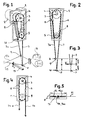
- the selection and the presentation of the weft threads 17 is carried out according to the pattern by electronic control of the electric motor 2, which is fastened to the housing 1 and has a drive wheel 4 connected to it in a form-fitting manner on the motor shaft 3.
- the deflection wheel 5 is rotatably fastened to the housing 1 and the center distance and the difference in diameter of the drive wheel 4 and the deflection wheel 5 are dimensioned such that the elongated straight belt strand of the looping belt 6 intersects in the transfer position U.
- the thread feeders 7, 7a are attached by means of fastening elements 8 and, guided by the guide 10, run parallel to the belt runs.
- the weft threads 17, 17a slide through the thread eyelets 9 of the thread feeders 7, 7a.
- the thread feeder 7 with the thread eyelet 9 and weft thread 17 is in the transfer position U while thread feeder 7a with the thread eyelet 9 with weft thread 17a is in the standby position B. If the weft 17a must be brought into the transfer position U according to the pattern, the electric motor 2 is controlled accordingly and the drive wheel 4 drives the belt 6 and moves the thread feeder 7a with the weft thread 17a into the transfer position U, while the thread feeder 7 inevitably into the standby position B. drives back.
- the weft threads 17, 17a are crossed halfway with a mutual distance so that the threads do not hang together.
- control program for the electric motors is programmed in such a way that of all the devices used, only the sample thread feeder is in the transfer position U, while all other thread feeders are in the standby position B ', as shown in FIG. 3, or one thread feeder is in the standby position B is.
- the thread feeders 14, 14a are arranged between two belts 12, 12a in the plane 11 of the belt pull fiber inlays 13 and are clamped to them in a form-fitting manner by means of the fastening elements 8. Due to the common plane of movement of the belt and the thread feeder, there are no bending and tilting moments as a result of acceleration and deceleration forces caused by the thread feeder movements on the belt. An additional guide for the thread feeder is not necessary with this arrangement. One thread feeder per device, or two, can be used.
Landscapes
- Engineering & Computer Science (AREA)
- Textile Engineering (AREA)
- Looms (AREA)
Applications Claiming Priority (2)
| Application Number | Priority Date | Filing Date | Title |
|---|---|---|---|
| CH3215/90A CH682498A5 (de) | 1990-10-05 | 1990-10-05 | Schussfadenauswahl- und Zuführvorrichtung für Webmaschine. |
| CH3215/90 | 1990-10-05 |
Publications (2)
| Publication Number | Publication Date |
|---|---|
| EP0478986A1 true EP0478986A1 (fr) | 1992-04-08 |
| EP0478986B1 EP0478986B1 (fr) | 1994-10-12 |
Family
ID=4251138
Family Applications (1)
| Application Number | Title | Priority Date | Filing Date |
|---|---|---|---|
| EP91115150A Expired - Lifetime EP0478986B1 (fr) | 1990-10-05 | 1991-09-07 | Dispositif de sélection et d'alimentation de fil de trame pour métiers à tisser |
Country Status (5)
| Country | Link |
|---|---|
| US (1) | US5172735A (fr) |
| EP (1) | EP0478986B1 (fr) |
| JP (1) | JP2620439B2 (fr) |
| CH (1) | CH682498A5 (fr) |
| DE (1) | DE59103223D1 (fr) |
Cited By (5)
| Publication number | Priority date | Publication date | Assignee | Title |
|---|---|---|---|---|
| EP0598264A1 (fr) * | 1992-11-16 | 1994-05-25 | Picanol N.V. | Dispositif pour sélectionner et présenter des fils de trame pour un métier à tisser |
| DE4325905C1 (de) * | 1993-08-02 | 1994-10-06 | Dornier Gmbh Lindauer | Vorrichtung zum Zuführen von Schußfäden zu einem Schußfadeneintragorgan in Webmaschinen |
| EP0896075A3 (fr) * | 1997-08-07 | 1999-06-16 | NUOVA VAMATEX S.p.A. | Dispositif de présentation de fil de trame pour métiers à tisser |
| EP1496145A1 (fr) * | 2003-07-10 | 2005-01-12 | Stäubli GmbH | Dispositif de sélection de trame pour métier à tisser |
| US7694697B2 (en) | 2006-05-31 | 2010-04-13 | Lindauer Dornier Gesellschaft Mbh | Apparatus for forming a selvedge on a gripper weaving machine |
Families Citing this family (1)
| Publication number | Priority date | Publication date | Assignee | Title |
|---|---|---|---|---|
| CN102507089B (zh) * | 2011-11-30 | 2013-07-24 | 长春理工大学 | 车门闭合力测试仪标定装置及方法 |
Citations (2)
| Publication number | Priority date | Publication date | Assignee | Title |
|---|---|---|---|---|
| EP0293558A1 (fr) * | 1987-04-03 | 1988-12-07 | GebràDer Sulzer Aktiengesellschaft | Sélecteur de trame pour un métier à tisser |
| EP0346966A1 (fr) * | 1988-06-17 | 1989-12-20 | Picanol N.V. | Dispositif pour présenter les fils de trame dans les métiers à tisser |
Family Cites Families (1)
| Publication number | Priority date | Publication date | Assignee | Title |
|---|---|---|---|---|
| DE3812960A1 (de) * | 1987-10-06 | 1989-04-20 | Textilma Ag | Greiferwebmaschine |
-
1990
- 1990-10-05 CH CH3215/90A patent/CH682498A5/de not_active IP Right Cessation
-
1991
- 1991-09-07 EP EP91115150A patent/EP0478986B1/fr not_active Expired - Lifetime
- 1991-09-07 DE DE59103223T patent/DE59103223D1/de not_active Expired - Lifetime
- 1991-10-04 US US07/771,190 patent/US5172735A/en not_active Expired - Lifetime
- 1991-10-04 JP JP3283808A patent/JP2620439B2/ja not_active Expired - Fee Related
Patent Citations (2)
| Publication number | Priority date | Publication date | Assignee | Title |
|---|---|---|---|---|
| EP0293558A1 (fr) * | 1987-04-03 | 1988-12-07 | GebràDer Sulzer Aktiengesellschaft | Sélecteur de trame pour un métier à tisser |
| EP0346966A1 (fr) * | 1988-06-17 | 1989-12-20 | Picanol N.V. | Dispositif pour présenter les fils de trame dans les métiers à tisser |
Cited By (10)
| Publication number | Priority date | Publication date | Assignee | Title |
|---|---|---|---|---|
| EP0598264A1 (fr) * | 1992-11-16 | 1994-05-25 | Picanol N.V. | Dispositif pour sélectionner et présenter des fils de trame pour un métier à tisser |
| BE1006347A3 (nl) * | 1992-11-16 | 1994-07-26 | Picanol Nv | Inrichting voor het presenteren van inslagdraden bij weefmachines. |
| US5400834A (en) * | 1992-11-16 | 1995-03-28 | Picanol, N.V. | Apparatus for selectively moving weft feeders between a rest position and a feed position |
| EP0763613A2 (fr) | 1992-11-16 | 1997-03-19 | Picanol N.V. | Dispositif pour sélectionner et présenter des fils de trame pour un métier à tisser |
| EP0763613A3 (fr) * | 1992-11-16 | 1997-10-01 | Picanol Nv | Dispositif pour sélectionner et présenter des fils de trame pour un métier à tisser |
| DE4325905C1 (de) * | 1993-08-02 | 1994-10-06 | Dornier Gmbh Lindauer | Vorrichtung zum Zuführen von Schußfäden zu einem Schußfadeneintragorgan in Webmaschinen |
| EP0638677A1 (fr) * | 1993-08-02 | 1995-02-15 | Lindauer Dornier Gesellschaft M.B.H | Dispositif pour amener des fils de trame à un inséreur de trame dans les métiers à tisser |
| EP0896075A3 (fr) * | 1997-08-07 | 1999-06-16 | NUOVA VAMATEX S.p.A. | Dispositif de présentation de fil de trame pour métiers à tisser |
| EP1496145A1 (fr) * | 2003-07-10 | 2005-01-12 | Stäubli GmbH | Dispositif de sélection de trame pour métier à tisser |
| US7694697B2 (en) | 2006-05-31 | 2010-04-13 | Lindauer Dornier Gesellschaft Mbh | Apparatus for forming a selvedge on a gripper weaving machine |
Also Published As
| Publication number | Publication date |
|---|---|
| JPH05132838A (ja) | 1993-05-28 |
| JP2620439B2 (ja) | 1997-06-11 |
| CH682498A5 (de) | 1993-09-30 |
| DE59103223D1 (de) | 1994-11-17 |
| US5172735A (en) | 1992-12-22 |
| EP0478986B1 (fr) | 1994-10-12 |
Similar Documents
| Publication | Publication Date | Title |
|---|---|---|
| DE4405776C1 (de) | Rotations-Kantendreher einer Webmaschine | |
| EP2580379B1 (fr) | Métier à tisser destiné à la fabrication de produits tissés avec un fil travaillé inséré | |
| DE69215324T2 (de) | Tetraaxialgewebe und Webstuhl zum Herstellen davon | |
| DE2548129A1 (de) | Vorrichtung zur bildung eines dreiachsigen gewebes und bestandteile derselben | |
| EP3141642A1 (fr) | Métier à tisser destiné à la fabrication de produits tissés dotés d'un fil à poser ou à tricoter incorporé | |
| DE69107517T3 (de) | Schussfadenzubringvorrichtung für Greiferwebmaschinen. | |
| DE2616910A1 (de) | Vorrichtung zur bildung einer dreherbindungs-webkante auf webstuehlen | |
| DE19924379A1 (de) | Elektronisch gesteuerte Musterschärmaschine | |
| EP0875610A2 (fr) | Dispositif pour la formation d'une lisière à pas de gaze, en particulier pour métiers à tisser | |
| EP0478986B1 (fr) | Dispositif de sélection et d'alimentation de fil de trame pour métiers à tisser | |
| EP0039009B1 (fr) | Procédé et dispositif pour l'insertion pneumatique d'un fil de trame dans l'inséreur de trame d'un métier à tisser multiple | |
| DE2041432C3 (de) | Garnklemme für Schußgarneintragsorgane an Webmaschinen | |
| DE2323732A1 (de) | Garnhandhabungsmechanismus fuer textilmaschinen, insbesondere webstuhl | |
| DE4325905C1 (de) | Vorrichtung zum Zuführen von Schußfäden zu einem Schußfadeneintragorgan in Webmaschinen | |
| DE69818588T2 (de) | Schussfadenzubringvorrichtung für Webmaschinen | |
| EP1052317B1 (fr) | Dispositif et procédé pour fournir un fil de tour à un métier à tisser | |
| DE4405778C2 (de) | Rotations-Kantendreher zur Verwendung in Webmaschinen | |
| DE3001069A1 (de) | Fadenzufuehrungs- und steuereinrichtung | |
| DE1535644B1 (de) | Schussfadenspeichervorrichtung fuer Webmaschinen mit Entnahme des Schussfadens von ausserhalb des Faches verbleibenden Schussfadenspulen | |
| DE2120584C3 (de) | Wellenfach-Webmaschine | |
| DE1535961B1 (de) | Vorrichtung zum Halten der Enden eingezogener Kettfaeden bei Kettfadeneinziehmaschinen | |
| DE558219C (de) | Verfahren und Vorrichtung zur Erzielung fester Webkanten | |
| DE102008036347A1 (de) | Verfahren zum Einbringen sich partiell in der Gewebebreite zusätzlich erstreckender Schussfäden während des maschinellen Webprozesses | |
| DE3202229A1 (de) | Verfahren und vorrichtung an webmaschinen zum zufuehren des schussfadens | |
| DE1760501B2 (de) | Schussgarn-mischeinrichtung fuer eine schuetzenlose webmaschine |
Legal Events
| Date | Code | Title | Description |
|---|---|---|---|
| PUAI | Public reference made under article 153(3) epc to a published international application that has entered the european phase |
Free format text: ORIGINAL CODE: 0009012 |
|
| AK | Designated contracting states |
Kind code of ref document: A1 Designated state(s): BE CH DE IT LI |
|
| 17P | Request for examination filed |
Effective date: 19920818 |
|
| 17Q | First examination report despatched |
Effective date: 19940314 |
|
| GRAA | (expected) grant |
Free format text: ORIGINAL CODE: 0009210 |
|
| AK | Designated contracting states |
Kind code of ref document: B1 Designated state(s): BE CH DE IT LI |
|
| REF | Corresponds to: |
Ref document number: 59103223 Country of ref document: DE Date of ref document: 19941117 |
|
| ITF | It: translation for a ep patent filed | ||
| PLBE | No opposition filed within time limit |
Free format text: ORIGINAL CODE: 0009261 |
|
| STAA | Information on the status of an ep patent application or granted ep patent |
Free format text: STATUS: NO OPPOSITION FILED WITHIN TIME LIMIT |
|
| 26N | No opposition filed | ||
| PGFP | Annual fee paid to national office [announced via postgrant information from national office to epo] |
Ref country code: DE Payment date: 20090730 Year of fee payment: 19 |
|
| PGFP | Annual fee paid to national office [announced via postgrant information from national office to epo] |
Ref country code: CH Payment date: 20100923 Year of fee payment: 20 |
|
| PGFP | Annual fee paid to national office [announced via postgrant information from national office to epo] |
Ref country code: IT Payment date: 20100923 Year of fee payment: 20 |
|
| PGFP | Annual fee paid to national office [announced via postgrant information from national office to epo] |
Ref country code: BE Payment date: 20100921 Year of fee payment: 20 |
|
| REG | Reference to a national code |
Ref country code: DE Ref legal event code: R119 Ref document number: 59103223 Country of ref document: DE Effective date: 20110401 |
|
| PG25 | Lapsed in a contracting state [announced via postgrant information from national office to epo] |
Ref country code: DE Free format text: LAPSE BECAUSE OF NON-PAYMENT OF DUE FEES Effective date: 20110401 |
|
| REG | Reference to a national code |
Ref country code: CH Ref legal event code: PL |
|
| BE20 | Be: patent expired |
Owner name: LINDAUER *DORNIER G.M.B.H. Effective date: 20110907 |