EP0638677A1 - Dispositif pour amener des fils de trame à un inséreur de trame dans les métiers à tisser - Google Patents
Dispositif pour amener des fils de trame à un inséreur de trame dans les métiers à tisser Download PDFInfo
- Publication number
- EP0638677A1 EP0638677A1 EP94111216A EP94111216A EP0638677A1 EP 0638677 A1 EP0638677 A1 EP 0638677A1 EP 94111216 A EP94111216 A EP 94111216A EP 94111216 A EP94111216 A EP 94111216A EP 0638677 A1 EP0638677 A1 EP 0638677A1
- Authority
- EP
- European Patent Office
- Prior art keywords
- weft
- thread
- guide
- straight
- carrier
- Prior art date
- Legal status (The legal status is an assumption and is not a legal conclusion. Google has not performed a legal analysis and makes no representation as to the accuracy of the status listed.)
- Granted
Links
Images
Classifications
-
- D—TEXTILES; PAPER
- D03—WEAVING
- D03D—WOVEN FABRICS; METHODS OF WEAVING; LOOMS
- D03D47/00—Looms in which bulk supply of weft does not pass through shed, e.g. shuttleless looms, gripper shuttle looms, dummy shuttle looms
- D03D47/34—Handling the weft between bulk storage and weft-inserting means
- D03D47/38—Weft pattern mechanisms
Definitions
- the invention relates to a device for feeding weft threads to a weft insertion element in weaving machines.
- the weft threads are drawn off from supply bobbins.
- the weft thread to be entered into the shed is selected by a special facility and presented to the weft insertion member in such a way that the thread can be grasped by the entry member and then entered into the shed.
- the thread feed device is equipped with a number of thread feeders for the individual weft threads drawn off from the supply bobbins, which have loops at their free ends for receiving the assigned thread.
- the thread feeders are moved from a rest position into a working position which corresponds to the respective thread feeder and from there back into the rest position.
- Various designs are known for such devices.
- a guide device for the thread feeder is known from DE-PS 36 18 445. Thereafter, this guide device consists of a spatially adjustable structure, on which a carrier part and a guide part arranged at a distance below it are arranged for the thread feeders. The carrier part and the guide part have straight guides which make the entirety of the thread feeders appear fan-shaped.
- the carrier part viewed in the direction of the weft insertion, is arranged in its longitudinal extent obliquely to the path of the weft insertion member and in the direction of the heald frames pointing to the adjustable structure.
- the straight guides in the carrier part are interlocked with one another in such a way that the thread feeders are guided displaceably in a spatially twisted fan area and that the individual eyelets of the thread feeders in the working position are in a compact arrangement on a line next to the path of the weft insertion element and essentially parallel to it .
- the straight guides mentioned are formed in a strip of the carrier part and a row of second straight guides is provided in the guide member, the two rows being arranged at an angle to one another such that the straight guides of both rows can be displaced Thread feeders form the spatially twisted fan surface.
- the known yarn feeder device ensures to a particular degree that the positions of the yarn feed for the first to the last weft yarn are so close together that it is possible to work for the weft yarn take-overs with a relatively small looper stroke with precisely punctiform yarn feed.
- a weft thread selection and feed device for weaving machines operated with an electric motor for the selective movement of thread feeders between a ready position and a transfer position for the weft thread.
- This device is characterized in that in a housing on a non-slip belt, which wraps around a drive wheel and a deflection wheel with a certain diameter difference and a certain distance, the extended straight belt rumble lines of action intersect at one point in the weft transfer position and that at each of the The two thread belts attached to the thread feeder are in the belt strand action line move and the thread feeder are so offset around the belt hitch that the one thread feeder is in the ready position, while the other thread feeder is in the transfer position and these positions are forcibly reversed by turning the drive wheel.
- This weft selection and feeding device gives the person skilled in the art the possibility to work with only a single thread feeder per device.
- this device offers the possibility of free electrical control and thus independence from the weaving machine control; for example, in the case of a weaving machine stop (because of warp or weft breakage) there is no inevitable threading.
- the object of the invention is, while maintaining the advantages resulting from the known solutions mentioned above, to take precautions which in particular allow the loom operators to equip looms as required, ie only with the necessary number of weft selection and feed devices.
- the weft selection and feed devices should be interchangeable between weaving machines in a cassette-like manner. It is also an object of the invention to take precautions which enable the weft thread selection and feeding devices to be changed easily with minimal assembly times.
- each weft selection device has a connector at the exit of the thread feeder, for example a connecting piece which can be inserted into a carrier part known per se equipped with straight guides and can be locked therein.
- the main advantage is that the individual weaving machine needs to be equipped with the only effectively required number of weft selection devices. This also means that the devices are exchangeable cassette-like, depending on the respective need for weft selection devices per loom, from loom to loom.
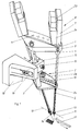
- the carrying and guiding device and the thread selection and feeding device are shown in FIG. 1 as a unit.
- the carrier part 1 and the guide part 2 are connected to one another by a connecting piece 3.
- Both the carrier part 1 and the guide part 2 can, as is known from DE-PS 36 18 445, preferably have a curved shape.
- the carrier part 1 has in a known manner external straight guides 4, which can be designed, for example, as through holes.
- external straight guides 4 instead of the thread feeder 5, the outlet of the housing 7 of the weft thread selection and feed device 8, which is designed as a socket 6, is received in the straight guides 4 and locked at position 9, for example by means of a clamping screw (not shown).
- Each thread feeder 5 is guided inside the socket 6 for the first time.
- a further guide takes place in the straight guide 10 of the guide part 2.
- the two outer weft selection and feed devices 8 are connected to the carrier part 1.
- the weft threads 11, 12 assigned to the devices 8 are to be entered here, for example, as a double weft.
- the eyelets 13 at the ends of the thread feeder 5 define the length and position of an imaginary line 14 on which the eyelets of all the thread feeder 5 of the device 8 must lie in their working position.
- the connecting piece 3 is clamped in a slotted block 15 by means of a screw 16. After loosening the screw 16, the entire device - supporting part 1, guide part 2 and weft thread selection and feed device 8 - can be axially displaced in the direction of the longitudinal axis of the connecting piece 3 and / or rotated about the longitudinal axis of the connecting piece. In this way, the angular position of the line 14 relative to the path of the weft insertion member 17 is adjustable and the overall height of the device relative to the path of the weft insertion member 17 can be changed.
- the block 15 is slidably arranged within a holder 18 in an elongated hole 19.
- the bracket 18 in turn is attached to a machine-fixed frame, not shown.
- the weft selection and feeding devices necessary for the weaving process are 8 held by means of nozzle 6 on the housing 7 in the carrier part 1.
- a clamp connection eg producible by means of a screw, ensures that the devices 8 are locked in position 9.
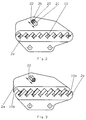
- the guide part 2 arranged below the carrier part 1 and carried by the connecting piece 3 is designed in such a way that the straight guides 10 therein are designed to be changeable for the thread feeders 5.
- the guide part 2 consists of a base part 2a and an upper part 2b which can be loosely connected to the base part 2a.
- the base part 2a is provided with half straight guides 10a and the upper part 2b with half straight guides 10b which are mirror images of the half straight guides 10a.
- a guide element 20 present in the base part 2a outside the straight guides 10a protrudes through a longitudinal guide 21 arranged in the upper part 2b.
- the upper part 2b is on the base part 2a slidable in the direction of the double arrow 22.
- the straight guides 10 for the thread feeder 5 can be lifted and restored in a few simple steps.
- the weft thread selection and feeding devices 8 connected to the carrying and guiding device in FIG. 1 have an electric motor 23 for driving the thread feeder 5, which is preferably a servomotor which is in signal-transmitting connection with the control device 24 also arranged on the housing 7.
Landscapes
- Engineering & Computer Science (AREA)
- Textile Engineering (AREA)
- Looms (AREA)
Applications Claiming Priority (2)
| Application Number | Priority Date | Filing Date | Title |
|---|---|---|---|
| DE4325905A DE4325905C1 (de) | 1993-08-02 | 1993-08-02 | Vorrichtung zum Zuführen von Schußfäden zu einem Schußfadeneintragorgan in Webmaschinen |
| DE4325905 | 1993-08-02 |
Publications (2)
| Publication Number | Publication Date |
|---|---|
| EP0638677A1 true EP0638677A1 (fr) | 1995-02-15 |
| EP0638677B1 EP0638677B1 (fr) | 1998-06-17 |
Family
ID=6494277
Family Applications (1)
| Application Number | Title | Priority Date | Filing Date |
|---|---|---|---|
| EP94111216A Expired - Lifetime EP0638677B1 (fr) | 1993-08-02 | 1994-07-19 | Dispositif pour amener des fils de trame à un inséreur de trame dans les métiers à tisser |
Country Status (4)
| Country | Link |
|---|---|
| US (1) | US5458163A (fr) |
| EP (1) | EP0638677B1 (fr) |
| JP (1) | JP2859540B2 (fr) |
| DE (2) | DE4325905C1 (fr) |
Cited By (2)
| Publication number | Priority date | Publication date | Assignee | Title |
|---|---|---|---|---|
| WO2014037282A2 (fr) | 2012-09-06 | 2014-03-13 | Picanol | Appareil permettant de présenter des fils de trame |
| CN112639192A (zh) * | 2018-09-11 | 2021-04-09 | 林道尔·多尼尔有限责任公司 | 具有纬纱选色装置的织机 |
Families Citing this family (3)
| Publication number | Priority date | Publication date | Assignee | Title |
|---|---|---|---|---|
| IT1293828B1 (it) * | 1997-08-07 | 1999-03-10 | Vamatex Nuova Spa | Presentatrice di trama per telai di tessitura |
| ATE217915T1 (de) * | 1997-09-11 | 2002-06-15 | Dornier Gmbh Lindauer | Steuerbare schussfadenzubringer- und - klemmvorrichtung und vorrichtungsanordnung zum minimieren des schussfadenabfalles bei der gewebeherstellung auf webmaschinen, insbesondere auf greiferwebmaschinen |
| DE10349644A1 (de) * | 2003-10-21 | 2005-06-02 | Picanol N.V. | Vorrichtung zum Auswählen und Zustellen von Schussfäden zu einem Greifer einer Greiferwebmaschine |
Citations (5)
| Publication number | Priority date | Publication date | Assignee | Title |
|---|---|---|---|---|
| DE3315320A1 (de) | 1983-04-27 | 1984-10-31 | Emil Jäger GmbH & Co KG, 4400 Münster | Vorrichtung zum eintragen von schussfaeden bei webmaschinen |
| DE3618445C1 (de) * | 1986-05-31 | 1987-07-02 | Dornier Gmbh Lindauer | Einrichtung zur Hinreichung von Schussfaeden fuer die Schussfadeneintragorgane bei schuetzenlosen Webmaschinen |
| EP0461524A1 (fr) * | 1990-06-11 | 1991-12-18 | NUOVA VAMATEX S.p.A. | Dispositif de présentation de fil de trame pour métiers à griffer |
| EP0478986A1 (fr) * | 1990-10-05 | 1992-04-08 | Lindauer Dornier Gesellschaft M.B.H | Dispositif de sélection et d'alimentation de fil de trame pour métiers à tisser |
| EP0598264A1 (fr) | 1992-11-16 | 1994-05-25 | Picanol N.V. | Dispositif pour sélectionner et présenter des fils de trame pour un métier à tisser |
Family Cites Families (7)
| Publication number | Priority date | Publication date | Assignee | Title |
|---|---|---|---|---|
| DE1801016C3 (de) * | 1967-10-25 | 1974-08-08 | Georg Fischer Ag Brugg, Brugg (Schweiz) | Mehrfarben-Schußwechsel-Vorrichtung für Webmaschinen |
| ES356720A1 (es) * | 1968-07-31 | 1970-02-16 | Camarasa Honge | Maquina selectora de hilos para labores de tejeduria y o- tras aplicaciones textiles. |
| DE2255918A1 (de) * | 1972-11-15 | 1974-06-12 | Lentz Fa S | Farbwaehler |
| US4191222A (en) * | 1978-02-28 | 1980-03-04 | Macart Textiles (Machinery) Limited | Weft presenter mechanisms |
| CH634885A5 (de) * | 1979-01-29 | 1983-02-28 | Loepfe Ag Geb | Elektronische abtastvorrichtung zur schussueberwachung an einer greiferschuetzenwebmaschine mit farbwechselvorrichtung. |
| JPS5953745A (ja) * | 1982-09-17 | 1984-03-28 | 伊藤忠テクスマック株式会社 | 多色用レピア織機のヨコ糸選択装置に於ける給糸レバ−の作動装置 |
| IT1230951B (it) * | 1989-06-30 | 1991-11-08 | Nuovo Pignone Spa | Dispositivo perfezionato di selezione e presentazione dei fili di trama per telai tessili ad alta velocita' |
-
1993
- 1993-08-02 DE DE4325905A patent/DE4325905C1/de not_active Expired - Fee Related
-
1994
- 1994-07-19 DE DE59406257T patent/DE59406257D1/de not_active Expired - Lifetime
- 1994-07-19 EP EP94111216A patent/EP0638677B1/fr not_active Expired - Lifetime
- 1994-07-29 US US08/282,968 patent/US5458163A/en not_active Expired - Fee Related
- 1994-07-29 JP JP6178221A patent/JP2859540B2/ja not_active Expired - Fee Related
Patent Citations (5)
| Publication number | Priority date | Publication date | Assignee | Title |
|---|---|---|---|---|
| DE3315320A1 (de) | 1983-04-27 | 1984-10-31 | Emil Jäger GmbH & Co KG, 4400 Münster | Vorrichtung zum eintragen von schussfaeden bei webmaschinen |
| DE3618445C1 (de) * | 1986-05-31 | 1987-07-02 | Dornier Gmbh Lindauer | Einrichtung zur Hinreichung von Schussfaeden fuer die Schussfadeneintragorgane bei schuetzenlosen Webmaschinen |
| EP0461524A1 (fr) * | 1990-06-11 | 1991-12-18 | NUOVA VAMATEX S.p.A. | Dispositif de présentation de fil de trame pour métiers à griffer |
| EP0478986A1 (fr) * | 1990-10-05 | 1992-04-08 | Lindauer Dornier Gesellschaft M.B.H | Dispositif de sélection et d'alimentation de fil de trame pour métiers à tisser |
| EP0598264A1 (fr) | 1992-11-16 | 1994-05-25 | Picanol N.V. | Dispositif pour sélectionner et présenter des fils de trame pour un métier à tisser |
Cited By (3)
| Publication number | Priority date | Publication date | Assignee | Title |
|---|---|---|---|---|
| WO2014037282A2 (fr) | 2012-09-06 | 2014-03-13 | Picanol | Appareil permettant de présenter des fils de trame |
| CN112639192A (zh) * | 2018-09-11 | 2021-04-09 | 林道尔·多尼尔有限责任公司 | 具有纬纱选色装置的织机 |
| CN112639192B (zh) * | 2018-09-11 | 2023-02-17 | 林道尔·多尼尔有限责任公司 | 具有纬纱选色装置的织机 |
Also Published As
| Publication number | Publication date |
|---|---|
| JP2859540B2 (ja) | 1999-02-17 |
| US5458163A (en) | 1995-10-17 |
| JPH07157947A (ja) | 1995-06-20 |
| DE59406257D1 (de) | 1998-07-23 |
| EP0638677B1 (fr) | 1998-06-17 |
| DE4325905C1 (de) | 1994-10-06 |
Similar Documents
| Publication | Publication Date | Title |
|---|---|---|
| EP0674031B2 (fr) | Mécanisme rotatif pour lisières "pas de gaze" pour métier à tisser | |
| DE2418799C3 (de) | Wählvorrichtung für die Nadelstangen und Fadengeber in einer Stickmaschine | |
| EP0763613A2 (fr) | Dispositif pour sélectionner et présenter des fils de trame pour un métier à tisser | |
| EP0902109B1 (fr) | Dispositif d'alimentation et de pinçage de fil de trame contrôlable et systeme comprenant ledit dispositif, pour la minimalisation des déchets de fil de trame durant le tissage sur métiers à tisser, plus particulièrement sur métiers à tisser à griffes | |
| EP0644286B1 (fr) | Arrangement pour présenter des fils de trame | |
| EP3141642A1 (fr) | Métier à tisser destiné à la fabrication de produits tissés dotés d'un fil à poser ou à tricoter incorporé | |
| DE69107517T3 (de) | Schussfadenzubringvorrichtung für Greiferwebmaschinen. | |
| DE2616910A1 (de) | Vorrichtung zur bildung einer dreherbindungs-webkante auf webstuehlen | |
| EP0638677A1 (fr) | Dispositif pour amener des fils de trame à un inséreur de trame dans les métiers à tisser | |
| DE3618445C1 (de) | Einrichtung zur Hinreichung von Schussfaeden fuer die Schussfadeneintragorgane bei schuetzenlosen Webmaschinen | |
| DE2349466C3 (de) | Verfahren und Vorrichtung zum gleichzeitigen und getrennten Überwachen zweier unter einem kleinen Winkel zusammenlaufender Fäden einer schützenlosen Webmaschine | |
| EP0068120B1 (fr) | Râtelier pour machine de filature | |
| DE4132696C2 (de) | Breithalter und dessen Verwendung bei einer Webmaschine | |
| EP0478986B1 (fr) | Dispositif de sélection et d'alimentation de fil de trame pour métiers à tisser | |
| EP0850329B1 (fr) | Metier a tisser | |
| EP1646573B1 (fr) | Systeme de traitement de fil et tensiometre pour fil | |
| DE69701240T2 (de) | Wickelmaschine | |
| DE68921480T2 (de) | Garn-Aufspulmaschine. | |
| DE19739853C2 (de) | Steuerbare Schußfadenzubringer- und -klemmvorrichtung und Vorrichtungsanordnung zum Minimieren des Schußfadenabfalles bei der Gewebeherstellung auf Webmaschinen, insbesondere auf Greiferwebmaschinen | |
| WO2008009332A1 (fr) | dispositif de placement de fils de trame dans un métier à tisser | |
| EP0980448B1 (fr) | Machine a tisser a lances | |
| EP0645484B1 (fr) | Métier à tisser multiphase à foule linéaire | |
| DE69103170T2 (de) | Schussfadenspeicher für Düsenwebmaschinen. | |
| DE69006443T2 (de) | Vorrichtung zum Zuführen von Schussfaden in Webmaschinen. | |
| DE8516286U1 (de) | Vorrichtung zum Zuführen von Fäden, Garnen u. dgl. zu einer Spulvorrichtung |
Legal Events
| Date | Code | Title | Description |
|---|---|---|---|
| PUAI | Public reference made under article 153(3) epc to a published international application that has entered the european phase |
Free format text: ORIGINAL CODE: 0009012 |
|
| AK | Designated contracting states |
Kind code of ref document: A1 Designated state(s): BE CH DE FR GB IT LI |
|
| 17P | Request for examination filed |
Effective date: 19950505 |
|
| 17Q | First examination report despatched |
Effective date: 19960122 |
|
| GRAG | Despatch of communication of intention to grant |
Free format text: ORIGINAL CODE: EPIDOS AGRA |
|
| GRAG | Despatch of communication of intention to grant |
Free format text: ORIGINAL CODE: EPIDOS AGRA |
|
| GRAH | Despatch of communication of intention to grant a patent |
Free format text: ORIGINAL CODE: EPIDOS IGRA |
|
| GRAH | Despatch of communication of intention to grant a patent |
Free format text: ORIGINAL CODE: EPIDOS IGRA |
|
| GRAA | (expected) grant |
Free format text: ORIGINAL CODE: 0009210 |
|
| AK | Designated contracting states |
Kind code of ref document: B1 Designated state(s): BE CH DE FR GB IT LI |
|
| REG | Reference to a national code |
Ref country code: CH Ref legal event code: EP |
|
| REG | Reference to a national code |
Ref country code: CH Ref legal event code: NV Representative=s name: DIPL.-ING. ETH H. R. WERFFELI PATENTANWALT |
|
| REF | Corresponds to: |
Ref document number: 59406257 Country of ref document: DE Date of ref document: 19980723 |
|
| GBT | Gb: translation of ep patent filed (gb section 77(6)(a)/1977) |
Effective date: 19980731 |
|
| ITF | It: translation for a ep patent filed | ||
| ET | Fr: translation filed | ||
| PLBE | No opposition filed within time limit |
Free format text: ORIGINAL CODE: 0009261 |
|
| STAA | Information on the status of an ep patent application or granted ep patent |
Free format text: STATUS: NO OPPOSITION FILED WITHIN TIME LIMIT |
|
| 26N | No opposition filed | ||
| REG | Reference to a national code |
Ref country code: GB Ref legal event code: IF02 |
|
| PGFP | Annual fee paid to national office [announced via postgrant information from national office to epo] |
Ref country code: FR Payment date: 20050608 Year of fee payment: 12 |
|
| PGFP | Annual fee paid to national office [announced via postgrant information from national office to epo] |
Ref country code: GB Payment date: 20050705 Year of fee payment: 12 |
|
| PG25 | Lapsed in a contracting state [announced via postgrant information from national office to epo] |
Ref country code: GB Free format text: LAPSE BECAUSE OF NON-PAYMENT OF DUE FEES Effective date: 20060719 |
|
| GBPC | Gb: european patent ceased through non-payment of renewal fee |
Effective date: 20060719 |
|
| REG | Reference to a national code |
Ref country code: FR Ref legal event code: ST Effective date: 20070330 |
|
| PG25 | Lapsed in a contracting state [announced via postgrant information from national office to epo] |
Ref country code: FR Free format text: LAPSE BECAUSE OF NON-PAYMENT OF DUE FEES Effective date: 20060731 |
|
| PGFP | Annual fee paid to national office [announced via postgrant information from national office to epo] |
Ref country code: DE Payment date: 20120921 Year of fee payment: 19 |
|
| PGFP | Annual fee paid to national office [announced via postgrant information from national office to epo] |
Ref country code: CH Payment date: 20130723 Year of fee payment: 20 Ref country code: BE Payment date: 20130722 Year of fee payment: 20 |
|
| PGFP | Annual fee paid to national office [announced via postgrant information from national office to epo] |
Ref country code: IT Payment date: 20130730 Year of fee payment: 20 |
|
| PG25 | Lapsed in a contracting state [announced via postgrant information from national office to epo] |
Ref country code: DE Free format text: LAPSE BECAUSE OF NON-PAYMENT OF DUE FEES Effective date: 20140201 |
|
| REG | Reference to a national code |
Ref country code: DE Ref legal event code: R119 Ref document number: 59406257 Country of ref document: DE Effective date: 20140201 |
|
| BE20 | Be: patent expired |
Owner name: *LINDAUER DORNIER G.M.B.H. Effective date: 20140719 |
|
| REG | Reference to a national code |
Ref country code: CH Ref legal event code: PL |