EP0479329A2 - Hacheur - Google Patents
Hacheur Download PDFInfo
- Publication number
- EP0479329A2 EP0479329A2 EP91118194A EP91118194A EP0479329A2 EP 0479329 A2 EP0479329 A2 EP 0479329A2 EP 91118194 A EP91118194 A EP 91118194A EP 91118194 A EP91118194 A EP 91118194A EP 0479329 A2 EP0479329 A2 EP 0479329A2
- Authority
- EP
- European Patent Office
- Prior art keywords
- knife
- knives
- chopper according
- drum
- chopper
- Prior art date
- Legal status (The legal status is an assumption and is not a legal conclusion. Google has not performed a legal analysis and makes no representation as to the accuracy of the status listed.)
- Granted
Links
Images






Classifications
-
- A—HUMAN NECESSITIES
- A01—AGRICULTURE; FORESTRY; ANIMAL HUSBANDRY; HUNTING; TRAPPING; FISHING
- A01F—PROCESSING OF HARVESTED PRODUCE; HAY OR STRAW PRESSES; DEVICES FOR STORING AGRICULTURAL OR HORTICULTURAL PRODUCE
- A01F29/00—Cutting apparatus specially adapted for cutting hay, straw or the like
- A01F29/09—Details
- A01F29/095—Mounting or adjusting of knives
-
- A—HUMAN NECESSITIES
- A01—AGRICULTURE; FORESTRY; ANIMAL HUSBANDRY; HUNTING; TRAPPING; FISHING
- A01F—PROCESSING OF HARVESTED PRODUCE; HAY OR STRAW PRESSES; DEVICES FOR STORING AGRICULTURAL OR HORTICULTURAL PRODUCE
- A01F12/00—Parts or details of threshing apparatus
- A01F12/40—Arrangements of straw crushers or cutters
Definitions
- the invention relates to a chopper, in particular an attached chopper for combine harvesters, according to the preamble of claim 1.
- Such a chopper is known from DE-GM 88 10 123. It is used to chop stalks, especially straw or the like.
- the object of the invention is to improve the chopping effect in a chopper of the type specified at the outset.
- this object is achieved in that at least one bar facing inwards is provided on the guide plate in the drum direction of rotation behind the counter knives. This bar forms an obstacle for the stalks, so that stalks conveyed along and parallel to the direction of flow are also deflected, gripped and chopped.
- the knives are also designed in a cutting shape on their end face. Surprisingly, it has been found that this additional cutting edge on the end face of the knives also detects and chops stalks that are conveyed parallel to the direction of flow, and that the stalks are already gripped and torn open when they penetrate the knife circle.
- the cutting edges on the front of the knife have another beneficial effect on the chopping process.
- a further bar is preferably provided at a distance from the first bar.
- the strips can consist of an angular profile or of another longitudinal profile, for example a straight profile.
- the strips are preferably adjustable, that is to say they can be adjusted and locked in the direction of the drum axis of rotation and away from it. In this way, the distance between the strips and in particular their ends facing the drum can be adjusted and optimized.
- the strips end at a short distance from the knife circle. This ensures that all stalks and especially thin stalks are gripped and chopped.
- the strips protrude into the knife circle and have recesses in the plane of rotation of the knives.
- a particularly good distraction effect is achieved. It is ensured that all stalks are conveyed into the circle of knives and gripped and chopped there.
- the stalks braked by the bar are transversely directed by the chopping material that slides in and reliably caught by the knives. So that the drum can still rotate, corresponding recesses for the knives must be provided at the points where the rotation planes of the knives intersect the strips.
- the knives can have a straight cutting edge on the front side.
- the knives can be serrated on the front.
- the teeth can be designed symmetrically.
- the teeth are ground or designed asymmetrically; the edges of the teeth run at different angles to the longitudinal axis of the knife.
- the angle of the leading edges of the teeth is preferably greater than the angle of the trailing edges. It is advantageous if the trailing edges run parallel to the longitudinal axis of the knife. The straws are then caught and chopped particularly reliably and effectively by the trailing edges of the teeth.
- the teeth are arranged symmetrically to the longitudinal axis of the knife and the angle of the inner edges of the teeth to the longitudinal axis of the knife is greater than the angle of the outer edges.
- the straws are then reliably and effectively gripped by the trailing edge of the trailing tooth.
- the knife can be turned over after a certain wear, so that the previously leading edge then forms the trailing edge. This leads to a simplification in maintenance and a doubling of the grinding intervals.
- the bar or the bars can be toothed to further improve the chopping effect.
- the bar or the bars are preferably pivotable. It is advantageous if the strips in the respective swivel position are noticeable.
- the bar or the bars can consist of a T-profile passing through the guide plate.
- the strips thus have the shape of a T-profile, so that straw can be directed and shredded by the strips protruding into the cutting space.
- the flange covers the opening in the guide plate.
- the guide plate is arranged pivotably behind the counter knives in the direction of rotation of the drum.
- the guide plate can preferably be locked in any position.
- a further advantageous development is characterized in that the guide plate extends radially inward behind the counter knives and in front of the bar in the direction of rotation of the drum, so that the chopped material is fed back to the bar and the knives.
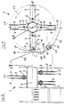
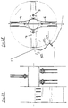
- the chopper shown in Figures 1 and 2 has a drum 1 with a knife shaft 2 which rotates about an essentially horizontal axis 3.
- a multiplicity of knives 4, 5, 6, 7 are pivotably arranged on the circumference of the knife shaft 2.
- the knife pivot axes 8 run parallel to the drum axis of rotation 3.
- the knives have 9 cutting edges on their long sides. The cutting edges are produced by grinding; however, other manufacturing methods are also possible.
- the chopper 1 also has a feed opening 10 and a guide plate 12 adjoining it in the direction of rotation 11 of the drum. The straw is introduced into the feed opening 10 through a feed plate 13.
- the feed opening 10 is thus formed by the end of this feed plate 13.
- the guide plate 12 runs essentially parallel and at a distance from the knife circulation circuit 14.
- fixed counter knives 15 are arranged behind the feed opening 10.
- the counter knife 15 are attached to the guide plate 12. They protrude into the knife circle 14 and are provided with teeth 16 on their upper side, that is to say in the side facing the drum direction of rotation 11.
- the guide plate 12 extends over an angle of approximately 90 degrees around the drum axis of rotation 3.
- the knives 4, 5, 6, 7 are also designed in a cutting shape on their respective end faces 17, 18, 19, 20.
- the cutting edges are designed by grinding; however, other manufacturing methods are also possible.
- Fig.1 four different knives 4,5,6,7 are shown. In practice, however, the same knives are always used for a chopper; only four different knives are therefore shown in FIG. 1 for the sake of the drawing.
- crescent-shaped recesses 17 are cut in on the end face (cf. FIGS. 19-23).
- the knife 5 is toothed on its end face 18, the teeth being designed asymmetrically (cf. FIGS. 11-14).
- the knife 6 is also toothed on its end face 19 (see FIGS. 15-18).
- the knife 7 has a smooth cutting edge on its end face 20 (cf. FIGS. 7-10).
- the knife 6 has a round cutting edge on its end face, the other knives 4, 5 and 7 have a straight cutting edge on the end face.
- the radius R of the round cutting edge is the same as the knife drum radius R.
- an inwardly facing bar 21 is provided in the drum direction of rotation 11 behind the counter knives 15.
- the bar 21 consists of a longitudinal profile or straight profile. It can be set, that is to say in the direction of the double arrow 22 towards the drum axis of rotation 3 and can be adjusted and locked away from it, for example by means of an elongated hole screw connection 23.
- the strip 21 or its end 24 facing the knife drum 1 ends at a short distance from the Knife circle 14, which amounts to 1 mm to 10 mm in the embodiment of FIG. 1.
- the end 24 of the bar 21 is ground obliquely, in such a way that the smallest distance between the end 24 of the bar 21 and the knife circle 14 is on the side of the bar 21 facing the drum direction of rotation 11.
- the rotation of the knives produces an air flow which essentially corresponds to the direction of rotation 11 of the drum 1. If a blade is conveyed lengthways and parallel to this direction of flow, it is reliably gripped and chopped by the front grinding of the knives. This chopping effect is considerably improved and reinforced by the bar 21.
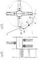
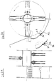
- Figures 3 and 4 show a further embodiment, at the same parts are provided with the same reference numerals.
- the strip 21 consists of an angle profile.
- a second bar 25 is provided in the drum rotation direction 11, which is also designed as an angle profile and which further improves the chopping effect.
- FIGS. 5 and 6 show a further embodiment in which the strips 21, 25 protrude into the knife circle 14. Corresponding recesses 27 are provided in the strips 21, 25 at the rotation planes 26 of the knives.
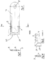
- FIGS. 7 to 10 show a knife 7 which has a straight cutting edge on its end face 20.
- the front edge 28 of the knife thus runs in a straight line.
- a knife 5 is shown in FIGS. 11 to 14, which likewise has a straight cutting edge on the end face 18. Furthermore, the knife 5 is toothed on the end face, the edges of the teeth 29 running at different angles to the knife longitudinal axis 30. The angle 32 between the leading edge 31 and the longitudinal axis 30 of the knife is greater than the angle between the trailing edge 33 and the longitudinal axis 30 of the knife.
- the "leading edge” 31 is understood to mean the edge leading in the direction of knife movement 34. Due to the asymmetrical grinding of the teeth just described, the straws are gripped and chopped particularly reliably and effectively and clogging of the teeth with chopped material is avoided (self-cleaning effect).
- the trailing edges 33 of the teeth 29 run, as shown in FIG. 13, parallel to the longitudinal axis 30 of the knife.
- FIGS. 15 to 18 show a knife 6, the end face 19 of which has a round cutting edge.
- the radius R of the round cutting edge of the end face of the knife 6 is the same size as the radius R of the drum 1, that is to say the radius R of the knife circle 14 Knife 6 is toothed on the end face 19.
- the middle tooth 35 which lies on the knife longitudinal axis 30, is designed symmetrically.
- the two adjoining teeth 36 are intrinsically asymmetrical, but mirror images of the longitudinal axis 30 of the knife. The arrangement is such that the teeth are arranged symmetrically to the longitudinal axis of the knife and that the angle of the inner edges of the teeth to the longitudinal axis of the knife is greater than the angle of the outer edges.
- FIGS. 19 to 23 show a knife 4 which has a straight cutting edge on its end face 17.
- the cutting edge consists of two tapered planes 40, 41, as can be seen from FIG. 23. Furthermore, 4 crescent-shaped recesses 42 are cut in on the end face of the knife.
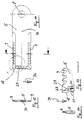
- the guide plate 12 is arranged pivotably in the drum rotation direction 11 behind the counter knives 15.
- the pivot point 51 is located immediately behind or below the knife box 52 holding the counter knife 15.
- the pivotability of the guide plate 12 is indicated by the double arrow 53.
- the pivoted-in position of the guide plate 12 is shown in dashed lines 12 '. In the pivoted-in position 12 ', the guide plate 12 runs in Drum direction of rotation 11 behind the counter knives 15 and in front of the bar 21 radially inwards, so that the chopped material is fed back to the bar 21 and the knives 4-7.
- the guide plate 12 is pivotally arranged in the direction of rotation 11 behind the counter knife box 52 at the pivot point 51 and can be locked in any position, as a result of which the distance between the strips 21 and the rotational path 14 of the knives 4-7 can be adjusted.
- the guide plate 12 is therefore formed behind the counter knife box 52 so that the chopped material is fed back to the bar 21 and the knives 4-7 in order to be further shredded.
- 26 and 27 show an exemplary embodiment in which two strips 21, 25 are arranged at a distance from one another on the guide plate 12 and in which the guide plate 12 can be pivoted about a pivot point 51 located immediately behind the knife box 52.
- the guide plate 12 is formed behind the counter knife box 52 so that the chopped material is fed back to the bar 21 and the knives 4, 5, 6, 7 for the purpose of further comminution.
- the bar 21 consists of a T-profile passing through the guide plate 12.
- the bar 21 protruding into the cutting space allows straw to be straightened and crushed.
- the flange 54 of this T-profile covers the opening in the guide plate.
- FIGS. 32 and 33 An embodiment is shown in FIGS. 32 and 33, in which the bar 21 is pivotable.
- the pivot axis 55 lies on the guide plate 12.
- the pivoting is effected by a lever 56 connected to the bar 21, which is guided in a circular slot 57 and can be locked.
- the bar 51 can be adjusted over a wide angular range.
- FIGS. 34 and 35 An embodiment is shown in FIGS. 34 and 35, in which the strip 21 can also be pivoted and locked about a pivot point 55 lying on the guide plate 12.
- the strip 21 consists of an angular profile with two legs 58, 59 running at right angles to one another.
Landscapes
- Life Sciences & Earth Sciences (AREA)
- Environmental Sciences (AREA)
- Threshing Machine Elements (AREA)
- Amplifiers (AREA)
- Harvester Elements (AREA)
- Debarking, Splitting, And Disintegration Of Timber (AREA)
Applications Claiming Priority (3)
| Application Number | Priority Date | Filing Date | Title |
|---|---|---|---|
| DE3929098 | 1989-09-01 | ||
| DE3929098 | 1989-09-01 | ||
| EP90116672A EP0415419B1 (fr) | 1989-09-01 | 1990-08-30 | Hachoir |
Related Parent Applications (1)
| Application Number | Title | Priority Date | Filing Date |
|---|---|---|---|
| EP90116672.8 Division | 1990-08-30 |
Publications (3)
| Publication Number | Publication Date |
|---|---|
| EP0479329A2 true EP0479329A2 (fr) | 1992-04-08 |
| EP0479329A3 EP0479329A3 (en) | 1992-07-08 |
| EP0479329B1 EP0479329B1 (fr) | 1996-12-04 |
Family
ID=6388450
Family Applications (2)
| Application Number | Title | Priority Date | Filing Date |
|---|---|---|---|
| EP90116672A Expired - Lifetime EP0415419B1 (fr) | 1989-09-01 | 1990-08-30 | Hachoir |
| EP91118194A Expired - Lifetime EP0479329B1 (fr) | 1989-09-01 | 1990-08-30 | Hacheur |
Family Applications Before (1)
| Application Number | Title | Priority Date | Filing Date |
|---|---|---|---|
| EP90116672A Expired - Lifetime EP0415419B1 (fr) | 1989-09-01 | 1990-08-30 | Hachoir |
Country Status (6)
| Country | Link |
|---|---|
| EP (2) | EP0415419B1 (fr) |
| AT (2) | ATE115828T1 (fr) |
| DD (1) | DD297541A5 (fr) |
| DE (3) | DE59008064D1 (fr) |
| DK (1) | DK0415419T3 (fr) |
| ES (1) | ES2067608T3 (fr) |
Cited By (9)
| Publication number | Priority date | Publication date | Assignee | Title |
|---|---|---|---|---|
| EP0568961A3 (fr) * | 1992-05-04 | 1994-02-09 | Biso Maschf Gmbh | |
| FR2727824A1 (fr) * | 1994-12-12 | 1996-06-14 | Deere & Co | Broyeur secondaire |
| WO1997011594A1 (fr) * | 1995-09-25 | 1997-04-03 | Biso B.V. | Hache-paille pour broyer la paille derriere les dispositifs de separation des grains d'une moissonneuse batteuse |
| EP0916252A1 (fr) * | 1997-11-07 | 1999-05-19 | Franz Schrattenecker | Hacheuse de produits de récolte en particulier de la paille |
| DE19749337A1 (de) * | 1997-11-07 | 1999-05-20 | Franz Schrattenecker | Häcksler zum Zerkleinern von Halmgut |
| EP0960561A1 (fr) * | 1998-05-26 | 1999-12-01 | Franz Schrattenecker | Hacheuse pour produits de récolte |
| EP1479282A1 (fr) * | 2003-05-17 | 2004-11-24 | Deere & Company | Couteau hache-paille |
| US7297053B2 (en) | 2004-07-16 | 2007-11-20 | Cnh America Llc | Rotary crop residue chopper apparatus with stiffener having air flow generating capability and method of making the same |
| US8092286B2 (en) | 2007-05-23 | 2012-01-10 | Cnh America Llc | Concave pan portion of an integral chopper assembly of a combine harvester |
Families Citing this family (18)
| Publication number | Priority date | Publication date | Assignee | Title |
|---|---|---|---|---|
| SE468784B (sv) * | 1991-07-22 | 1993-03-22 | Rekordverken Ab | Slaghack, foersedd med laegesinstaellbara motknivar vilka i undanfaellt laege kan taeckas med ett skydd |
| DE4134878A1 (de) * | 1991-10-23 | 1993-04-29 | Deere & Co | Verfahren zum herstellen einer pendelnd aufgehaengten trennleiste fuer eine haeckselvorrichtung, trennleiste und haeckselvorrichtung |
| DE4135165C2 (de) * | 1991-10-24 | 1998-04-09 | Biso Maschf Gmbh | Häcksler |
| DE4218235A1 (de) * | 1992-06-03 | 1993-12-09 | Kloeckner Humboldt Deutz Ag | Strohverteilung am Mähdrescher |
| DE4431802A1 (de) * | 1994-09-07 | 1996-03-14 | Claas Ohg | Anbauhäcksler mit Breitverteileraustrag für zu zerkleinerndes Gut, insbesondere Stroh/Spreu-Gemisch für/an einem Mähdrescher |
| DE9416851U1 (de) * | 1994-10-11 | 1994-12-15 | BISO-Schrattenecker Betriebs- und Verwaltungs-GmbH, 32289 Rödinghausen | Schlegelmesser und Gegenmesser für Häcksler |
| DE19530028A1 (de) * | 1995-08-16 | 1997-02-20 | Wilhelm Jakobi | Strohhäcksler zum Zerkleinern von Halmgut hinter den Kornabscheideeinrichtungen eines Mähdreschers |
| US8590355B2 (en) | 2004-04-19 | 2013-11-26 | Rasspe Systemtechnik Gmbh & Co. Kg | Chopping blade and counterblade for a chopping device and process for its production |
| US7862413B2 (en) | 2009-05-18 | 2011-01-04 | Cnh America Llc | Remotely positionable interruption plate |
| CN102696364A (zh) * | 2012-06-28 | 2012-10-03 | 莱恩农业装备有限公司 | 一种卡刀自动调整碎草机构 |
| DE102013108292A1 (de) | 2013-08-01 | 2015-02-05 | Claas Selbstfahrende Erntemaschinen Gmbh | Mähdrescher mit einer Häckselvorrichtung |
| US9635813B2 (en) * | 2014-07-08 | 2017-05-02 | Cnh Industrial America Llc | Residue handling system for an agricultural harvester |
| CN104620787B (zh) * | 2014-12-31 | 2016-06-01 | 广西壮族自治区农业科学院农产品加工研究所 | 一种饲料加工用切削装置 |
| DE102015218726A1 (de) * | 2015-09-29 | 2017-03-30 | Deere & Company | Strohhäcksler für einen Mähdrescher mit Gegenmessern und Reibleiste |
| US10111384B2 (en) * | 2015-10-09 | 2018-10-30 | Cnh Industrial America Llc | Agricultural chopper with linked counter knives and shear bar |
| NL1043860B1 (en) * | 2020-12-07 | 2022-07-07 | Regnerus Piet | Mower-chopper apparatus |
| CN113261435A (zh) * | 2021-05-12 | 2021-08-17 | 山东理工大学 | 一种双辊甩刀与直刀组合式稻麦碎秸秆均匀抛撒装置 |
| US12471535B2 (en) | 2021-11-17 | 2025-11-18 | Cnh Industrial America Llc | Residue chopper with counterblades and fins |
Family Cites Families (8)
| Publication number | Priority date | Publication date | Assignee | Title |
|---|---|---|---|---|
| DE862383C (de) * | 1950-11-03 | 1953-01-12 | Standardwerk Wilhelm Schulze K | Strohzerreisseinrichtung fuer Dreschmaschinen |
| DE834463C (de) * | 1950-12-31 | 1952-03-20 | Helga Gronert | Zerkleinerungsmaschine, insbesondere fuer landwirtschaftliche Erzeugnisse |
| DE877070C (de) * | 1951-07-21 | 1953-05-21 | Ley Hans | Vorrichtung zur AEnderung der Schnittlaenge bei Schneidemaschinen mit umlaufender Messerwelle und Gegenlage, insbesondere Strohschneidern |
| FR1141447A (fr) * | 1955-09-15 | 1957-09-02 | Max Grumbach & Co Fa | Dispositif de fragmentation des substances destinées en particulier à l'alimentation du bétail |
| US2842175A (en) * | 1955-10-24 | 1958-07-08 | Ernest S Thompson | Straw chopper for combine |
| GB2116834B (en) * | 1982-02-05 | 1985-07-17 | Agri Tech Limited | Machine for chopping straw |
| ES2026587T3 (es) * | 1988-03-10 | 1992-05-01 | Franz Prof. Dr.-Ing. Wieneke | Cortapajas deshilachador. |
| DE3823116A1 (de) * | 1988-07-08 | 1990-01-11 | Deere & Co | Trennleiste fuer eine zerkleinerungsvorrichtung |
-
1990
- 1990-08-30 DE DE59008064T patent/DE59008064D1/de not_active Expired - Fee Related
- 1990-08-30 EP EP90116672A patent/EP0415419B1/fr not_active Expired - Lifetime
- 1990-08-30 EP EP91118194A patent/EP0479329B1/fr not_active Expired - Lifetime
- 1990-08-30 DK DK90116672.8T patent/DK0415419T3/da active
- 1990-08-30 DE DE59010592T patent/DE59010592D1/de not_active Expired - Lifetime
- 1990-08-30 AT AT90116672T patent/ATE115828T1/de not_active IP Right Cessation
- 1990-08-30 ES ES90116672T patent/ES2067608T3/es not_active Expired - Lifetime
- 1990-08-30 AT AT91118194T patent/ATE145784T1/de not_active IP Right Cessation
- 1990-08-30 DE DE9015677U patent/DE9015677U1/de not_active Expired - Lifetime
- 1990-09-03 DD DD90343779A patent/DD297541A5/de unknown
Cited By (15)
| Publication number | Priority date | Publication date | Assignee | Title |
|---|---|---|---|---|
| EP0568961A3 (fr) * | 1992-05-04 | 1994-02-09 | Biso Maschf Gmbh | |
| FR2727824A1 (fr) * | 1994-12-12 | 1996-06-14 | Deere & Co | Broyeur secondaire |
| US5928080A (en) * | 1995-09-25 | 1999-07-27 | Biso B.V | Device for chopping the stalks after the ears of corn have been cut off in a combine harvester |
| WO1997011594A1 (fr) * | 1995-09-25 | 1997-04-03 | Biso B.V. | Hache-paille pour broyer la paille derriere les dispositifs de separation des grains d'une moissonneuse batteuse |
| EP1438887A3 (fr) * | 1995-09-25 | 2004-09-15 | Biso B.V. | Hache-paille pour broyer la paille derrière les dispositifs de séparation des grains d'une moissonneuse batteuse |
| DE19749337C2 (de) * | 1997-11-07 | 1999-09-02 | Schrattenecker | Häcksler zum Zerkleinern von Halmgut |
| DE19749337A1 (de) * | 1997-11-07 | 1999-05-20 | Franz Schrattenecker | Häcksler zum Zerkleinern von Halmgut |
| US6120373A (en) * | 1997-11-07 | 2000-09-19 | Schrattenecker; Franz | Chopper for breaking up stalks, chiefly straw |
| US6126098A (en) * | 1997-11-07 | 2000-10-03 | Schrattenecker; Franz | Chopper for breaking up stalks |
| EP0916252A1 (fr) * | 1997-11-07 | 1999-05-19 | Franz Schrattenecker | Hacheuse de produits de récolte en particulier de la paille |
| EP0960561A1 (fr) * | 1998-05-26 | 1999-12-01 | Franz Schrattenecker | Hacheuse pour produits de récolte |
| EP1479282A1 (fr) * | 2003-05-17 | 2004-11-24 | Deere & Company | Couteau hache-paille |
| US7555889B2 (en) | 2003-05-17 | 2009-07-07 | Deere & Company | Chopper knife for a straw chopper |
| US7297053B2 (en) | 2004-07-16 | 2007-11-20 | Cnh America Llc | Rotary crop residue chopper apparatus with stiffener having air flow generating capability and method of making the same |
| US8092286B2 (en) | 2007-05-23 | 2012-01-10 | Cnh America Llc | Concave pan portion of an integral chopper assembly of a combine harvester |
Also Published As
| Publication number | Publication date |
|---|---|
| EP0479329B1 (fr) | 1996-12-04 |
| DK0415419T3 (da) | 1995-05-15 |
| ES2067608T3 (es) | 1995-04-01 |
| ATE145784T1 (de) | 1996-12-15 |
| EP0415419B1 (fr) | 1994-12-21 |
| EP0415419A3 (en) | 1991-10-23 |
| EP0479329A3 (en) | 1992-07-08 |
| DE59010592D1 (de) | 1997-01-16 |
| DD297541A5 (de) | 1992-01-16 |
| EP0415419A2 (fr) | 1991-03-06 |
| DE9015677U1 (de) | 1991-03-21 |
| DE59008064D1 (de) | 1995-02-09 |
| ATE115828T1 (de) | 1995-01-15 |
Similar Documents
| Publication | Publication Date | Title |
|---|---|---|
| EP0415419B1 (fr) | Hachoir | |
| EP0538599B1 (fr) | Hacheuse | |
| EP0486887B1 (fr) | Appareil à cueillir pour une moissonneuse | |
| DE19749338C2 (de) | Häcksler zum Zerkleinern von Halmgut, vorzugsweise von Stroh | |
| EP1671532B1 (fr) | Rotor hacheur | |
| DE102019108306A1 (de) | Schneidmühle zum schneidenden Zerkleinern von Proben | |
| EP0255459A1 (fr) | Plateau de coupe à lames contrarotatives synchronisées | |
| EP1269821A1 (fr) | Outil pivotant, rotor et leur utilisation | |
| DE3934862A1 (de) | Pflueckvorrichtung zum ernten von halmfruechten, insbesondere mais | |
| EP0124137A2 (fr) | Méthode et dispositif pour le broyage de produits végétaux | |
| DE4242740A1 (de) | Zerkleinerungsmaschine | |
| DE3631485A1 (de) | Strohhaecksler | |
| DE7502435U (de) | Haeckselmaschine | |
| DE102020002342A1 (de) | Mulchgerät | |
| DE6931693U (de) | Feldhaecksler | |
| DE3626456C2 (fr) | ||
| DE69607030T2 (de) | Messern für die schraubenwinde von misch- und schneidemaschinen | |
| DE3727535A1 (de) | Pflueckvorrichtung zum ernten von halmfruechten, insbesondere mais | |
| EP1048353A1 (fr) | Appareil broyeur | |
| DE9319071U1 (de) | Schneidwerk für Gartenhäcksler mit Messerwalze | |
| DE2608145A1 (de) | Kreiselmaeher mit haeckseleinrichtung | |
| DE1025196B (de) | Vorrichtung zum Zerkleinern von Weichgut, beispielsweise Viehfutter | |
| DE19850534A1 (de) | Konditioniereinrichtung für Feldhäcksler | |
| DE3705623A1 (de) | Zerkleinerungsvorrichtung, insbesondere aktenvernichter | |
| EP0645076B1 (fr) | Ramasseuse-hâcheuse |
Legal Events
| Date | Code | Title | Description |
|---|---|---|---|
| PUAI | Public reference made under article 153(3) epc to a published international application that has entered the european phase |
Free format text: ORIGINAL CODE: 0009012 |
|
| AC | Divisional application: reference to earlier application |
Ref document number: 415419 Country of ref document: EP |
|
| AK | Designated contracting states |
Kind code of ref document: A2 Designated state(s): AT BE DE DK ES FR GB IT SE |
|
| PUAL | Search report despatched |
Free format text: ORIGINAL CODE: 0009013 |
|
| AK | Designated contracting states |
Kind code of ref document: A3 Designated state(s): AT BE DE DK ES FR GB IT SE |
|
| 17P | Request for examination filed |
Effective date: 19920728 |
|
| 17Q | First examination report despatched |
Effective date: 19940218 |
|
| RAP1 | Party data changed (applicant data changed or rights of an application transferred) |
Owner name: BISO B.V. |
|
| GRAH | Despatch of communication of intention to grant a patent |
Free format text: ORIGINAL CODE: EPIDOS IGRA |
|
| GRAA | (expected) grant |
Free format text: ORIGINAL CODE: 0009210 |
|
| AC | Divisional application: reference to earlier application |
Ref document number: 415419 Country of ref document: EP |
|
| AK | Designated contracting states |
Kind code of ref document: B1 Designated state(s): AT BE DE DK ES FR GB IT SE |
|
| PG25 | Lapsed in a contracting state [announced via postgrant information from national office to epo] |
Ref country code: DK Effective date: 19961204 Ref country code: ES Free format text: THE PATENT HAS BEEN ANNULLED BY A DECISION OF A NATIONAL AUTHORITY Effective date: 19961204 |
|
| REF | Corresponds to: |
Ref document number: 145784 Country of ref document: AT Date of ref document: 19961215 Kind code of ref document: T |
|
| GBT | Gb: translation of ep patent filed (gb section 77(6)(a)/1977) |
Effective date: 19961205 |
|
| REF | Corresponds to: |
Ref document number: 59010592 Country of ref document: DE Date of ref document: 19970116 |
|
| ITF | It: translation for a ep patent filed | ||
| ET | Fr: translation filed | ||
| PG25 | Lapsed in a contracting state [announced via postgrant information from national office to epo] |
Ref country code: BE Effective date: 19970831 |
|
| PLBE | No opposition filed within time limit |
Free format text: ORIGINAL CODE: 0009261 |
|
| STAA | Information on the status of an ep patent application or granted ep patent |
Free format text: STATUS: NO OPPOSITION FILED WITHIN TIME LIMIT |
|
| 26N | No opposition filed | ||
| BERE | Be: lapsed |
Owner name: BISO B.V. Effective date: 19970831 |
|
| REG | Reference to a national code |
Ref country code: GB Ref legal event code: IF02 |
|
| PGFP | Annual fee paid to national office [announced via postgrant information from national office to epo] |
Ref country code: SE Payment date: 20040823 Year of fee payment: 15 |
|
| PGFP | Annual fee paid to national office [announced via postgrant information from national office to epo] |
Ref country code: FR Payment date: 20050810 Year of fee payment: 16 |
|
| PG25 | Lapsed in a contracting state [announced via postgrant information from national office to epo] |
Ref country code: IT Free format text: LAPSE BECAUSE OF NON-PAYMENT OF DUE FEES;WARNING: LAPSES OF ITALIAN PATENTS WITH EFFECTIVE DATE BEFORE 2007 MAY HAVE OCCURRED AT ANY TIME BEFORE 2007. THE CORRECT EFFECTIVE DATE MAY BE DIFFERENT FROM THE ONE RECORDED. Effective date: 20050830 |
|
| PG25 | Lapsed in a contracting state [announced via postgrant information from national office to epo] |
Ref country code: SE Free format text: LAPSE BECAUSE OF NON-PAYMENT OF DUE FEES Effective date: 20050831 |
|
| EUG | Se: european patent has lapsed | ||
| PGFP | Annual fee paid to national office [announced via postgrant information from national office to epo] |
Ref country code: GB Payment date: 20060724 Year of fee payment: 17 |
|
| PGFP | Annual fee paid to national office [announced via postgrant information from national office to epo] |
Ref country code: AT Payment date: 20060818 Year of fee payment: 17 |
|
| REG | Reference to a national code |
Ref country code: FR Ref legal event code: ST Effective date: 20070430 |
|
| GBPC | Gb: european patent ceased through non-payment of renewal fee |
Effective date: 20070830 |
|
| PG25 | Lapsed in a contracting state [announced via postgrant information from national office to epo] |
Ref country code: FR Free format text: LAPSE BECAUSE OF NON-PAYMENT OF DUE FEES Effective date: 20060831 |
|
| PG25 | Lapsed in a contracting state [announced via postgrant information from national office to epo] |
Ref country code: AT Free format text: LAPSE BECAUSE OF NON-PAYMENT OF DUE FEES Effective date: 20070830 |
|
| PG25 | Lapsed in a contracting state [announced via postgrant information from national office to epo] |
Ref country code: GB Free format text: LAPSE BECAUSE OF NON-PAYMENT OF DUE FEES Effective date: 20070830 |
|
| PGFP | Annual fee paid to national office [announced via postgrant information from national office to epo] |
Ref country code: DE Payment date: 20090828 Year of fee payment: 20 |
|
| PG25 | Lapsed in a contracting state [announced via postgrant information from national office to epo] |
Ref country code: DE Free format text: LAPSE BECAUSE OF EXPIRATION OF PROTECTION Effective date: 20100830 |