EP0479629A1 - Beton-Schalungspaneel - Google Patents
Beton-Schalungspaneel Download PDFInfo
- Publication number
- EP0479629A1 EP0479629A1 EP91402252A EP91402252A EP0479629A1 EP 0479629 A1 EP0479629 A1 EP 0479629A1 EP 91402252 A EP91402252 A EP 91402252A EP 91402252 A EP91402252 A EP 91402252A EP 0479629 A1 EP0479629 A1 EP 0479629A1
- Authority
- EP
- European Patent Office
- Prior art keywords
- rods
- concrete
- concrete formwork
- formwork panel
- panel
- Prior art date
- Legal status (The legal status is an assumption and is not a legal conclusion. Google has not performed a legal analysis and makes no representation as to the accuracy of the status listed.)
- Withdrawn
Links
- 238000009416 shuttering Methods 0.000 title abstract 3
- 238000009415 formwork Methods 0.000 claims abstract description 37
- 239000003365 glass fiber Substances 0.000 claims abstract description 17
- 230000007935 neutral effect Effects 0.000 claims description 7
- 238000009435 building construction Methods 0.000 claims description 5
- 239000004593 Epoxy Substances 0.000 claims description 4
- 229920005989 resin Polymers 0.000 claims description 4
- 239000011347 resin Substances 0.000 claims description 4
- 229920001187 thermosetting polymer Polymers 0.000 claims description 4
- 229920001567 vinyl ester resin Polymers 0.000 claims description 4
- 239000011152 fibreglass Substances 0.000 claims description 2
- 239000007788 liquid Substances 0.000 abstract description 8
- 238000010276 construction Methods 0.000 abstract description 7
- 229920002635 polyurethane Polymers 0.000 description 11
- 239000004814 polyurethane Substances 0.000 description 11
- 230000035882 stress Effects 0.000 description 11
- 239000004743 Polypropylene Substances 0.000 description 9
- 239000000835 fiber Substances 0.000 description 9
- 238000004519 manufacturing process Methods 0.000 description 9
- -1 polypropylene Polymers 0.000 description 9
- 229920001155 polypropylene Polymers 0.000 description 9
- 239000000463 material Substances 0.000 description 7
- 238000000034 method Methods 0.000 description 5
- 238000005452 bending Methods 0.000 description 4
- 239000002184 metal Substances 0.000 description 4
- 239000002131 composite material Substances 0.000 description 3
- 230000007797 corrosion Effects 0.000 description 3
- 238000005260 corrosion Methods 0.000 description 3
- 229920003023 plastic Polymers 0.000 description 3
- 239000004033 plastic Substances 0.000 description 3
- 230000006835 compression Effects 0.000 description 2
- 238000007906 compression Methods 0.000 description 2
- 230000007547 defect Effects 0.000 description 2
- 238000009826 distribution Methods 0.000 description 2
- 230000000694 effects Effects 0.000 description 2
- 230000002706 hydrostatic effect Effects 0.000 description 2
- 238000000465 moulding Methods 0.000 description 2
- 230000002787 reinforcement Effects 0.000 description 2
- 230000003014 reinforcing effect Effects 0.000 description 2
- 230000035939 shock Effects 0.000 description 2
- 229920002994 synthetic fiber Polymers 0.000 description 2
- 239000002023 wood Substances 0.000 description 2
- 210000001217 buttock Anatomy 0.000 description 1
- 238000005266 casting Methods 0.000 description 1
- 230000002860 competitive effect Effects 0.000 description 1
- 238000001035 drying Methods 0.000 description 1
- 230000006355 external stress Effects 0.000 description 1
- 238000007654 immersion Methods 0.000 description 1
- 238000009434 installation Methods 0.000 description 1
- 230000000750 progressive effect Effects 0.000 description 1
Images


Classifications
-
- E—FIXED CONSTRUCTIONS
- E04—BUILDING
- E04G—SCAFFOLDING; FORMS; SHUTTERING; BUILDING IMPLEMENTS OR AIDS, OR THEIR USE; HANDLING BUILDING MATERIALS ON THE SITE; REPAIRING, BREAKING-UP OR OTHER WORK ON EXISTING BUILDINGS
- E04G9/00—Forming or shuttering elements for general use
- E04G9/02—Forming boards or similar elements
- E04G9/05—Forming boards or similar elements the form surface being of plastics
-
- E—FIXED CONSTRUCTIONS
- E04—BUILDING
- E04G—SCAFFOLDING; FORMS; SHUTTERING; BUILDING IMPLEMENTS OR AIDS, OR THEIR USE; HANDLING BUILDING MATERIALS ON THE SITE; REPAIRING, BREAKING-UP OR OTHER WORK ON EXISTING BUILDINGS
- E04G15/00—Forms or shutterings for making openings, cavities, slits, or channels
- E04G15/02—Forms or shutterings for making openings, cavities, slits, or channels for windows, doors, or the like
-
- E—FIXED CONSTRUCTIONS
- E04—BUILDING
- E04G—SCAFFOLDING; FORMS; SHUTTERING; BUILDING IMPLEMENTS OR AIDS, OR THEIR USE; HANDLING BUILDING MATERIALS ON THE SITE; REPAIRING, BREAKING-UP OR OTHER WORK ON EXISTING BUILDINGS
- E04G9/00—Forming or shuttering elements for general use
- E04G9/02—Forming boards or similar elements
- E04G2009/028—Forming boards or similar elements with reinforcing ribs on the underside
Definitions
- the invention relates to a concrete formwork panel. It will find its application in particular in the field of building construction.
- metal panels do not resist corrosion; moreover all the accidental deformations which they would be brought to undergo are permanent. Finally, these are heavy panels that are difficult to handle.
- the wood panels are only mentioned for the record since their possibilities of use are extremely limited. In addition, it is an expensive material, hardly compatible with mass production.
- the main object of the present invention is to present a concrete formwork panel which is insensitive to corrosion and which offers mechanical characteristics of resistance to deformation very significantly improved compared to existing plastic panels. Not only does the panel of the invention better withstand external stresses by deforming much more weakly, but also it has a capacity for impact resistance which is also greatly improved.
- the concrete formwork panel which will find its application in particular in the field of building construction, formed of a bearing face stiffened by ribs, is characterized in that it is reinforced by rods made of continuous fibers .
- the present invention relates to a concrete formwork panel. It will find its application in particular in the field of building construction.
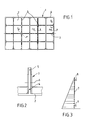
- Figure 1 shows the view of the rear face of a concrete formwork panel.
- the front face is flat and the poured concrete is applied to it.
- the panel (1) consists of a support plate (2) stiffened by a set of interlocking ribs (3).
- the dimensions of the panel are 600 ⁇ 900 mm with a spacing between ribs and with respect to the edges of 300 mm.
- the panel is entirely made of polypropylene, that is to say a rot-proof material, which is resistant to shocks.
- the formwork panel (1) of the present invention has great rigidity. For this, it is reinforced by rods made of continuous glass fibers.
- Figure 2 shows a sectional view of a rib (3), in which there is the establishment of two rods (4 and 5). These rods extend over the entire length of the rib (3), the perimeter (6) of the panel (1), as illustrated in FIG. 1, is also provided with reinforcing rods.
- the rods (4 and 5) extend at the foot and at the top of the ribs.
- the rods (5) located at the top of the ribs reinforce the tensile strength of the panel (1).
- the rods (4 and 5) are fixed over their entire length in the ribs (3). In this way, the rods and the polypropylene located in the same zones undergo the same deformations by the phenomenon of adhesion.
- the neutral fiber (6) By defining the neutral fiber (6) as the axis illustrated in Figure 2 of the rib (3) where the stress is zero, the deformations and stresses in the polypropylene ribs (3) and in the rods (4 and 5) are proportional to the distance from the neutral fiber (6).
- the rods (4 and 5) used are preferably rough or twisted in order to increase their adhesion in the rib (3).
- This adhesion is interesting because it avoids a distribution of the stress throughout the rod, which would be the case if the rod was fixed only by its ends. By fixing the rod over its entire length, it acts as a function of the local stress, hence an overall elongation very much less than that which would be encountered with a rod subjected to a uniform maximum stress.
- the reinforcement of the formwork panel by the installation of rods in continuous fibers has the advantage of obtaining a Young's modulus relating to the composite materials equal to or even greater than the polypropylene loaded with short fibers.
- the impact resistance is not altered but on the contrary increased thanks to the continuity of the fibers and their capacity to transmit the stresses from one end to the other of the panel.
- the elastic properties of continuous glass fiber rods also make it possible to considerably reduce the hysteresis phenomenon of polypropylene linked to the bending of the panel.
- the rods (4 and 5) are composed of a core of parallel glass fibers impregnated with a thermosetting resin, such as an epoxy or a vinylester.
- a thermosetting resin such as an epoxy or a vinylester.
- the surface of the rod is preferably twisted to accentuate the attachment with the polypropylene. Young's modulus of these rods is 46,000 M.Pa.
- the breaking stress is 139 Da.N / mm 2 .
- the diameters of the rods that have been tested range from 4 to 10 mm.
- the concrete formwork ends can also be manufactured according to the technique of the present invention. They are arranged between two formwork panels and the end of the veil ensures the concrete stops and trunk the end of the veil.
- the end piece (7) as illustrated in FIG. 3, can be compared to a beam subjected to a triangular hydrostatic load. This load corresponds to the pressure exerted by the liquid concrete on the beam.
- the end piece (7) must withstand loads, taking into account the density of the concrete (2,4).
- the end piece (7) has two fixing points (8 and 9) located at each of its ends. The end is therefore subjected to a significant bending force.
- Figures 4a, 4b, 4c and 4d show different common sections used to make the beams making up the end piece.
- Figure 4a shows a simple T section without heel.
- Figure 4b shows a simple T beam with heel.
- Figure 4c shows a double T beam without heel.
- Figure 4d shows a double T beam with heel.
- a rod (10) is placed at the base of the T and a rod (11) is placed at the top of the T.
- the beams are reinforced by the presence of these rods made of continuous fibers, which makes it possible to reach - to have a very high moment of inertia and to reduce the amount of material used.
- the end piece is preferably made from a compact unexpanded polyurethane with a density between 1 and 1.15 with high mechanical characteristics. Its Young's modulus is greater than 2000 M.Pa and its impact resistance is greater than 60 kg / m 2 .
- the reinforcing rods (10 and 11) comprise a core made of parallel glass fibers impregnated with a thermosetting resin such as an epoxy or a vinylester. The surface of the rods is twisted to accentuate their attachment to the polyurethane. The Young's modulus of the rods is 46,000 M.Pa and their tensile stress is 139 Da.N / mm 2 .
- the rods are arranged on either side of the neutral axis of the T or double T section and behave like a beam - bar assembly whose cohesion is provided by the polyurethane.
- the rods (10) located in the lower part of the T or in the heel reinforce the tensile strength of the profile and limit the elongation of the polyurethane.
- Associated with the rods (11) located in the upper part of the compressed T they contribute to the rigidity of the profile in composite material. This rigidity, quantified by the moment of inertia, is proportional to the section and the spacing of the rods.
- the load of continuous glass fibers characterized by the positioning of the rods, has the effect of raising the Young's modulus of the polyurethane in proportions which can vary from 50 to 100%, not to reduce the resistance to shock and considerably reduce the hysteresis phenomenon linked to flexion of the buttocks.
- Figure 5 shows an end beam (12) in section view.
- This beam (12) is subjected to a bending force resulting from the thrust of the liquid concrete which tends to cause it to flex. This results in the creation of a compressed zone (13) and a tight zone (14), arranged on either side of the neutral fiber (15).
- the rods (10 and 11) are fixed in the beam (12) over their entire length.
- the rods (10 and 11) and the polyurethane located in the same areas undergo the same deformations by the phenomenon of adhesion. These deformations are proportional to the distance from the neutral fiber (15).
- the rods (10 and 11) used are preferably twisted on the surface to increase the adhesion phenomenon.
- the reservation frames are intended to be placed between two formwork panels when pouring concrete to occupy the future location of a door or window.
- the reservation frame makes this area inaccessible to poured concrete.
- the frame (16), as illustrated in Figure 6, is similar to a gantry subjected to loads or pressures uniformly distributed or triangular depending on the location.
- the uprights (17 and 18) are subjected to progressive forces with at the top already a load corresponding to the immersion of the frame (16) in the liquid concrete.
- the transverse beam (19), for its part, is subjected to a regular pressure force since it works at constant depth in the formwork.
- the reservation frame (16) is therefore required to withstand significant hydrostatic pressure loads taking into account the density of the concrete (2,4).
- the reservation frame (16) is constructed from beams reinforced by the presence of rods of continuous glass fibers.
- the frame (16) is made from a compact unexpanded polyurethane with a density between 1 and 1.15 with high mechanical characteristics: Young's modulus greater than 2000 M.Pa and impact resistance more than 60 kg / m 2 .
- the reinforcements are made of rods composed of a core of parallel glass fibers impregnated with a thermosetting resin such as an epoxy or vinylester. The surface of the rods is twisted to accentuate the bond with the polyurethane.
- the Young's modulus of the rods is of the order of 46,000 M.Pa and its breaking stress is 139 Da.N / mm2.
- FIG. 7 represents the gantry (16) which forms the reservation frame.
- This consists of uprights (17 and 18) formed in the example chosen by double T beams with heel, identical to those illustrated in Figure 4d.
- the crosspiece (19) is formed by the assembly of two angles placed at the end of the beams which form the uprights (17 and 18).
- the rigidity of the frame (16) can be significantly improved thanks to the presence of connecting bars shown diagrammatically by dashed lines in FIG. 7.
- longitudinal rods of continuous glass fibers (10, 11) are integrated at the top and at the base of the T, such as illustrated in Figure 8 which shows the frame (16) in cross section.
- the rods (10 and 11) significantly increase the moment of inertia of the beams and make it possible to reduce the amount of material used.
- the rods are arranged on either side of the neutral axis of the double-T section and behave like a beam-bar assembly whose cohesion is provided by the polyurethane.
- the rods (10) located in the lower part of the double T or in the heel reinforce the tensile strength of the profile and limit the elongation of the polyurethane.
- the rods (11) located in the upper part of the double T are compressed and they contribute to the rigidity of the composite material profile.
- This rigidity quantified by the moment of inertia, is proportional to the section and the spacing of the rods (10 and 11).
- rods made of continuous glass fibers has the effect of raising the Young's modulus of the polyurethane in proportions which can vary from 50 to 100% and of not reducing its impact resistance.
- the hysteresis phenomenon, linked to the section of the beam elements, is considerably reduced.
Landscapes
- Engineering & Computer Science (AREA)
- Architecture (AREA)
- Mechanical Engineering (AREA)
- Civil Engineering (AREA)
- Structural Engineering (AREA)
- Forms Removed On Construction Sites Or Auxiliary Members Thereof (AREA)
Applications Claiming Priority (2)
| Application Number | Priority Date | Filing Date | Title |
|---|---|---|---|
| FR9012374 | 1990-10-01 | ||
| FR909012374A FR2667341B1 (fr) | 1990-10-01 | 1990-10-01 | Panneau de coffrage a beton. |
Publications (1)
| Publication Number | Publication Date |
|---|---|
| EP0479629A1 true EP0479629A1 (de) | 1992-04-08 |
Family
ID=9401015
Family Applications (1)
| Application Number | Title | Priority Date | Filing Date |
|---|---|---|---|
| EP91402252A Withdrawn EP0479629A1 (de) | 1990-10-01 | 1991-08-14 | Beton-Schalungspaneel |
Country Status (2)
| Country | Link |
|---|---|
| EP (1) | EP0479629A1 (de) |
| FR (1) | FR2667341B1 (de) |
Citations (7)
| Publication number | Priority date | Publication date | Assignee | Title |
|---|---|---|---|---|
| US3313674A (en) * | 1962-10-02 | 1967-04-11 | Foam Products Corp | Laminate panel |
| DE2012032A1 (de) * | 1970-03-13 | 1971-09-23 | Massenberg, Gert, 4300 Essen | Schalungstafel |
| FR2175669A2 (en) * | 1972-03-17 | 1973-10-26 | Setil | Lightweight building slab or panel - of polyurethane foam contng foamed glass aggregate |
| FR2275605A1 (fr) * | 1974-06-19 | 1976-01-16 | Francois Allard | Element de construction |
| GB1471661A (en) * | 1974-05-06 | 1977-04-27 | Reed Malik Ltd | Shutters for supporting concrete or the like |
| DE3113810A1 (de) * | 1981-04-06 | 1982-10-21 | Gebrüder Kömmerling Kunststoffwerke GmbH, 6780 Pirmasens | Kunststoff-profilstab |
| EP0146844A2 (de) * | 1983-12-16 | 1985-07-03 | Gerhard Dingler | Grossflächige, plattenförmige Bauteile |
-
1990
- 1990-10-01 FR FR909012374A patent/FR2667341B1/fr not_active Expired - Fee Related
-
1991
- 1991-08-14 EP EP91402252A patent/EP0479629A1/de not_active Withdrawn
Patent Citations (7)
| Publication number | Priority date | Publication date | Assignee | Title |
|---|---|---|---|---|
| US3313674A (en) * | 1962-10-02 | 1967-04-11 | Foam Products Corp | Laminate panel |
| DE2012032A1 (de) * | 1970-03-13 | 1971-09-23 | Massenberg, Gert, 4300 Essen | Schalungstafel |
| FR2175669A2 (en) * | 1972-03-17 | 1973-10-26 | Setil | Lightweight building slab or panel - of polyurethane foam contng foamed glass aggregate |
| GB1471661A (en) * | 1974-05-06 | 1977-04-27 | Reed Malik Ltd | Shutters for supporting concrete or the like |
| FR2275605A1 (fr) * | 1974-06-19 | 1976-01-16 | Francois Allard | Element de construction |
| DE3113810A1 (de) * | 1981-04-06 | 1982-10-21 | Gebrüder Kömmerling Kunststoffwerke GmbH, 6780 Pirmasens | Kunststoff-profilstab |
| EP0146844A2 (de) * | 1983-12-16 | 1985-07-03 | Gerhard Dingler | Grossflächige, plattenförmige Bauteile |
Also Published As
| Publication number | Publication date |
|---|---|
| FR2667341B1 (fr) | 1994-10-14 |
| FR2667341A1 (fr) | 1992-04-03 |
Similar Documents
| Publication | Publication Date | Title |
|---|---|---|
| FR2510163A1 (fr) | Procede de renforcement d'une poutre en bois | |
| FR2562837A1 (fr) | Elements composites de construction et procede pour la realisation de structures multi-directionnelles par formage et/ou assemblage de tels elements | |
| FR2523460A1 (fr) | Ski forme par injection et son procede de fabrication | |
| FR2670523A1 (fr) | Element prefabrique de mur en beton arme. | |
| FR2572788A1 (fr) | Structure porteuse composite | |
| FR2640938A1 (de) | ||
| EP0479629A1 (de) | Beton-Schalungspaneel | |
| EP1135565B1 (de) | Triangulierte holzbauweisen, wie gitterträger, brücke, decken | |
| FR2691993A1 (fr) | Poutres composées à membrures renforcées. | |
| EP3175057B1 (de) | Ein vorgespanntes tragelement | |
| FR2606057A1 (fr) | Renforcement d'elements de charpente par insertion de plaques a haute resistance | |
| FR2507647A1 (fr) | Panneau de construction prefabrique et procede pour la realisation d'un tel panneau | |
| FR2684401A1 (fr) | Procede pour realiser un ouvrage d'art tubulaire et ouvrage s'y rapportant. | |
| FR2581587A1 (fr) | Procede de fabrication de parois en matiere plastique de grandes dimensions, et de planeite amelioree, et produits obtenus | |
| FR2956422A1 (fr) | Poutrelle metallique pour la fabrication de planchers. | |
| FR2635349A1 (fr) | Panneau muni de raidisseurs de renforcement | |
| FR2685026A1 (fr) | Profile pour element de coffrage. | |
| FR2835272A1 (fr) | Dispositif de mur isolant et procede pour sa fabrication | |
| FR2760478A1 (fr) | Element de construction de type poutre | |
| FR2747708A1 (fr) | Poutre en bois ou analogue pour structure de construction | |
| EP0479628A1 (de) | Ausrichtlatte, Entschalungslatte, Bewehrungsanschluss und magnetische Latte für Bauarbeiten auf dem Bauplatz und bei der Vorfertigung | |
| EP0744511A1 (de) | Spannbetonträger, sowie Verfahren zu seiner Herstellung | |
| EP4372168B1 (de) | Bausatz für eine dämmschalung einer gebäudewand und verfahren zum bau einer gebäudewand mit dämmschalung | |
| EP0135240A2 (de) | Selbsttragende Platte für einen doppelten Fussboden | |
| BE431225A (de) |
Legal Events
| Date | Code | Title | Description |
|---|---|---|---|
| PUAI | Public reference made under article 153(3) epc to a published international application that has entered the european phase |
Free format text: ORIGINAL CODE: 0009012 |
|
| AK | Designated contracting states |
Kind code of ref document: A1 Designated state(s): BE DE ES GB IT LU NL |
|
| STAA | Information on the status of an ep patent application or granted ep patent |
Free format text: STATUS: THE APPLICATION IS DEEMED TO BE WITHDRAWN |
|
| 18D | Application deemed to be withdrawn |
Effective date: 19921009 |