EP0479720A1 - Procédé et dispositif pour poser des faux planchers surélevés ainsi que des supports pour faux planchers surélevés - Google Patents
Procédé et dispositif pour poser des faux planchers surélevés ainsi que des supports pour faux planchers surélevés Download PDFInfo
- Publication number
- EP0479720A1 EP0479720A1 EP91810744A EP91810744A EP0479720A1 EP 0479720 A1 EP0479720 A1 EP 0479720A1 EP 91810744 A EP91810744 A EP 91810744A EP 91810744 A EP91810744 A EP 91810744A EP 0479720 A1 EP0479720 A1 EP 0479720A1
- Authority
- EP
- European Patent Office
- Prior art keywords
- supports
- support
- floor
- height
- foot
- Prior art date
- Legal status (The legal status is an assumption and is not a legal conclusion. Google has not performed a legal analysis and makes no representation as to the accuracy of the status listed.)
- Granted
Links
Images


Classifications
-
- E—FIXED CONSTRUCTIONS
- E04—BUILDING
- E04F—FINISHING WORK ON BUILDINGS, e.g. STAIRS, FLOORS
- E04F15/00—Flooring
- E04F15/02—Flooring or floor layers composed of a number of similar elements
- E04F15/024—Sectional false floors, e.g. computer floors
-
- E—FIXED CONSTRUCTIONS
- E04—BUILDING
- E04F—FINISHING WORK ON BUILDINGS, e.g. STAIRS, FLOORS
- E04F15/00—Flooring
- E04F15/02—Flooring or floor layers composed of a number of similar elements
- E04F15/024—Sectional false floors, e.g. computer floors
- E04F15/02447—Supporting structures
- E04F15/02464—Height adjustable elements for supporting the panels or a panel-supporting framework
- E04F15/0247—Screw jacks
- E04F15/02476—Screw jacks height-adjustable from the upper side of the floor
-
- E—FIXED CONSTRUCTIONS
- E04—BUILDING
- E04F—FINISHING WORK ON BUILDINGS, e.g. STAIRS, FLOORS
- E04F15/00—Flooring
- E04F15/02—Flooring or floor layers composed of a number of similar elements
- E04F15/024—Sectional false floors, e.g. computer floors
- E04F15/02447—Supporting structures
- E04F15/02464—Height adjustable elements for supporting the panels or a panel-supporting framework
- E04F15/02488—Height adjustable elements for supporting the panels or a panel-supporting framework filled with material hardening after application
-
- E—FIXED CONSTRUCTIONS
- E04—BUILDING
- E04F—FINISHING WORK ON BUILDINGS, e.g. STAIRS, FLOORS
- E04F21/00—Implements for finishing work on buildings
- E04F21/20—Implements for finishing work on buildings for laying flooring
Definitions
- Raised floors (also called “raised floors”) essentially consist of floor plates lined up next to each other and these supporting, height-adjustable supports, which, arranged in a regular grid, rest on a bare floor (bare ceiling).
- Such raised floors are mainly used in office, administrative, industrial and commercial buildings, etc., in order to be able to lay a wide variety of lines in the cavity under the floor slabs on the unfinished floor (electrical power supply lines, control and data lines, pipes for ventilation, heating, Sewage, etc.). Thanks to easy access after lifting off individual floor slabs, such installations can be changed at any time and adapted to changing needs.
- each support is individually measured, offset and adjusted in height at a grid point on the bare floor; Despite unevenness in the floor, each support must stand exactly perpendicular to the grid point, for which purpose the support foot is lined with wedges or supports with joint arrangements are used.
- the supports have screw threads throughout for height adjustment.
- the adjustment is usually carried out by placing a floor slab over adjacent, already placed and the new pillar and then checking the plate position using a spirit level; it is often necessary to remove and replace the heavy plates. So far, the double floor installation has been very tedious due to the heavy physical work close to the floor and only progresses slowly even with trained personnel.
- the aim of the present invention is to considerably accelerate the progress of work compared to previously and to make the work considerably easier in order to avoid severe fatigue, back and joint damage etc.
- the horizontal auxiliary plane can be identical to the support plane of the floor slabs or can be parallel to this. It can e.g. are slightly lower, in which case the set and adjusted supports are supplemented by an additional, uniform support part before the base plates are placed on the head part.
- the invention further relates to a device for performing the aforementioned method according to the invention.
- This device is characterized by a frame which defines the auxiliary level above the field and which has height-adjustable support members for positioning the device and releasable holding means for the head parts of the supports to be introduced in the field, around the head parts at points on the frame corresponding to the grid points, aligned with the height of the auxiliary level and protruding vertically from it temporarily.
- This device enables the supports to be introduced and set in groups, their vertical position and alignment with the grid points being given to the whole group after the auxiliary level or the frame has been leveled.
- the invention relates to a prefabricated raised floor support, which is particularly developed and suitable for use in the aforementioned method and with the aforementioned device (although it can also be used elsewhere). It is assumed that there is a raised floor support with a head section and foot section, which are adjustable relative to each other for the purpose of adjusting the height of the support. According to the invention, such a support is characterized in that the head part and the foot part are guided loosely with respect to one another and are continuously displaceable in the direction of the support axis without mutual rotation, and in that locking means are provided for mutually fixing the relative position between the head part and the foot part.
- the raised floor support according to the invention designed in this way (in contrast to known supports with thread adjustment) makes it possible to adjust the height of several supports at the same time - and also simultaneously with the Leveling the auxiliary level - to be carried out.
- a device which is intended to compensate for unevenness in the raw floor before the double floor installation.
- the device can be moved on the bare floor and has lateral holding devices for semi-finished material strands. These strands are individually lowered to grid points on the bare floor, glued there and, after the adhesive has set, cut to a defined height using a circular saw. In this way, base elements with a defined level are formed on the bare floor. Only after such preparation and without further use of the device are the actual supports - in one piece and of uniform height - placed on the base elements. Again, they must be connected to the bases before the panels can be placed on the supports.
- prefabricated supports consisting of a head part and foot part are introduced into the device, placed on the grid points, adjusted in height and fixed.
- the supports are specially designed for this method and the device. This significantly speeds up and facilitates the work.
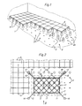
- the double floor shown in FIG. 1 during the laying and partly already laid has supports 5 arranged in a regular grid and resting on the unfinished floor 1.
- These carry floor plates 6 lined up next to each other, the contacting corners of four plates each resting on a support 5.
- Usually square plates are e.g. 60 cm edge length used, but other formats are also possible; the grid in which the supports 5 are arranged is of course given by the plate format.
- Grid points on the bare floor 1 that are not yet occupied are designated by 2.
- additional supports can be placed within the grid squares on grid positions 2a, e.g. to support the plates 6 in the middle when there is a high floor load.
- the supports 5 Since the unfinished floor 1 is usually fraught with level inaccuracies and uneven, the supports 5 must be adjustable in height or adjustable in length. In addition, each support must stand with its longitudinal axis vertically and precisely on the grid point, even if the support is uneven. Both of the aforementioned conditions must be met so that the base plates 6 carried by the supports 5 form a horizontal, flat base surface at the desired height.
- the supports 5 are shown in a highly simplified manner with the head part 7 and foot part 8, which are adjustable relative to one another for the purpose of height adjustment of the supports.
- the supports 5 can be connected to one another at their upper ends by horizontal struts (not shown) which run along the sides of the plate and / or diagonally to the plates.
- Intermediate layers (not shown), on which the plates 6 come to rest, can also be provided on the head part 7 of each support after the supports have been set and adjusted.
- an auxiliary level 4 (FIG. 3 ) leveled at a distance above the bare floor 1 (the field 3 can only comprise one row or, as shown, several rows of grid points 2).
- the height of the horizontal auxiliary plane 4 is of course related to the target position of the base plates 6, ie the position of the auxiliary plane can be identical to the underside of the plates 6 or else deviate, if, as mentioned above, on the supports 5 after their height adjustment Liner is put on.
- leveled auxiliary level 4 are then set and fixed on the grid points 2 within the field 3, the prefabricated supports 5 to the respective height corresponding to the (different) distance between the (uneven) raw floor 1 and the auxiliary level 4.
- the base plates 6 are finally laid on the supports set and set in this way. The latter can either take place "field by field” immediately or later over a larger, contiguous floor area.
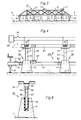
- the device 10 has a frame 11, which is preferably designed as a torsion-resistant and bending-resistant lattice structure and which defines the auxiliary level 4. Height-adjustable support members 16, 16 'serve to position and level the device 10 above the field 3 in the manner described below. Furthermore, the device 10 has releasable holding means 15 (which are not shown in the present example) for the head parts 7 of the supports 5.
- the holding means serve to temporarily fix the supports 5 - at least their head part 7 - at locations on the frame 11 which correspond to the grid points 2, in such a way that the head parts 7 are aligned with the level of the auxiliary plane 4 and perpendicularly from it stand out.
- the device 10 has four arms 12 projecting laterally from the rectangular frame 11.
- the arms 12 are either set up to align the frame with adjacent supports 5 that have already been placed (top in FIG. 2), or they are provided with height-adjustable support feet 16 (bottom in FIG. 2).
- the support feet 16 are preferably fastened removably;
- the ends of the cantilevers 12 (without support feet 16 ′) lie on the supports that have already been placed, the height of the latter is thus “removed” by the device 10.
- the outriggers 12 can, as indicated, be provided with sleeves 13 or the like, which grip over the supports 5 serving as a reference.
- the device 10 or the auxiliary level 4 is then leveled by adjusting the height of the support feet 16 on the other arms 12.
- the device 10 can be provided with leveling elements 17 for this purpose.
- the process can be carried out by manually adjusting the support feet (e.g. by means of a threaded spindle) and simultaneously observing the leveling members 17, but it can also be automated, for example using electronic leveling means and e.g. Support feet adjustable pneumatically or by means of a thread and stepper motor drive 16.
- auxiliary level When leveling, it is by no means necessary that supports that have already been set and used serve as a reference, rather the auxiliary level can also be leveled by means of a reference system spanning the entire floor area of the room (for example optically using a laser beam ). Additional support feet 16 'are of course used above all at the beginning of work in a room if no reference supports 5 are available yet. Retractable and extendable wheels, castors or the like can also be provided for convenient handling and change of location of the device 10.
- a device 10 is particularly advantageous because a plurality of supports 5 (or at least their head part) are positioned jointly or simultaneously on the grid points 2 within the relevant field 3 and kept perpendicular.
- a plurality of supports 5 or at least their head part
- the height adjustment of the supports introduced in this way If the leveling takes place by approaching the auxiliary level 4 to the bare floor 1 (lowering the device from above), the height adjustment can be achieved to a certain extent automatically and at the same time as the leveling by shortening the supports introduced.
- "telescopically" adjustable supports as are described below, for example, are particularly useful.
- the supports introduced after the leveling of the auxiliary level 4 can be accomplished by extending the (previously briefly set) supports starting from the auxiliary level 4.
- both conventional, thread-adjustable and telescopically adjustable supports are suitable for this type of adjustment, although the latter can be set more quickly and conveniently.
- the foot part 8 of each support that comes to rest on the bare floor 1 must be fastened there. This can be done in a manner known per se, in particular by gluing.
- the above-mentioned holding means 15 for the head part of the supports 5 on the device 10 are located at points 2 '(FIG. 3) which correspond to the grid points 2 of the field 3.
- the holding means should be such that after the setting, setting and fixing of the supports 5 they release them so that the device 10 can be lifted off and positioned over a next field 3.
- the supports can be attached to the device e.g. be mechanically, electromagnetically, pneumatically, etc. releasably held.
- first at least three supports 5 are placed in the edge region of a field 3, and the height can be adjusted and fixed in order to thereby determine the auxiliary level 4;
- the remaining supports 5 of the field 3 are then introduced, onto which the already level set and fixed auxiliary level.
- This procedure corresponds to the use of two different (not shown) device parts in succession, namely a "measuring frame”, which only serves to set and adjust the first supports and thus to determine the auxiliary level, and a "mounting frame”, which then introduces the further supports , but is not set up for leveling, but focuses on the first mentioned supports.
- the device 10A has a lower part 61 and an upper part 65, both of which are designed as grid-like frames.
- the lower part 61 can be aligned and leveled in the manner described, e.g. by means of support feet 16 and dragonflies 17 or the like. It has stops 62 for the foot parts 51 of supports 50, such that the foot parts 51 come to rest on the raw floor 1 via the grid points 2 when the lower part 61 is aligned laterally.
- the upper part 65 can be placed on the lower part by means of legs 66 (only one shown) which fit in the centerings 63 on the lower part.
- the underside of the upper part 65 determines - with the lower part 61 leveled - the auxiliary level 4.
- electromagnets 67 are shown schematically, which are fed from a current source 68 and release all head parts simultaneously when a switch 69 is opened.
- the device 10A works as follows: First, the lower part 61 is positioned laterally and leveled to the desired height. Then the column base parts 51 are placed on grid points 2 with the aid of the stops 62 and fixed to the bare floor, e.g. stuck.
- the upper part 65 - preferably still separate from the lower part - is fitted with the support head parts and then placed on the lower part 61.
- the shaft 53 of an upper part engages with play in a bore 52 (FIG. 9) of the associated column foot part 51. All columns then have their desired height corresponding to the distance between the auxiliary level 4 and the raw floor 1.
- the game mentioned makes it possible for the foot part to be crooked according to the unevenness of the unfinished floor 1.
- Double floor supports which are particularly suitable and designed for use with the described method and the device 10 used are shown as exemplary embodiments in FIGS. 5 to 11.
- Such prefabricated supports each have a head part and a foot part, which are adjustable relative to one another for the purpose of height adjustment of the support.
- the supports shown here are characterized in that their head part and foot part are guided loosely in relation to each other and can be moved continuously in the direction of the support axis without mutual rotation. Locking means are also provided on these supports in order to mutually fix the relative position between the head part and the foot part.
- the head part 21 consists essentially of a tube section.
- the foot part is formed by a plurality of rods 30 arranged in parallel around the support axis 29; in the present case there are six bars 30, as a minimum three such bars are required.
- the head part 21 has a fixed ring 22 and a lower guide ring 23 on the inner tube wall. In both rings, half bores corresponding to the diameter of the rods 30 are provided, in which the rods are individually guided so as to be longitudinally movable along the tube wall.
- At the level of the ring 22 and radially inside the rods 30 there is a ring of six clamping jaws 24, each of which has a supplementary half-bore for each rod.
- the six clamping jaws 24 are held together loosely, for example by means of a resilient wire ring 25, and are therefore radially movable.
- the inside of the clamping jaws 24 forms a uniform conical surface with which the corresponding conical outer surface of a clamping block 26 interacts.
- the shaft of an axially arranged clamping screw 28 sits in a threaded bore of the clamping block 26, the head of which rests on a web 27 which is welded diametrically into the pipe section 21.
- the clamping jaws 24 and the clamping block 26 together form a wedge clamping device arranged centrally in the head part 21, which acts radially on all rods 30 and can be actuated from above by means of the clamping screw 28: in a lower position of the clamping block 26 (on the right in FIG. 5) the clamping jaws 24 are loosened and the rods 30 are longitudinally displaceable, on the other hand, when the screw 28 is tightened and the clamping block 26 is raised (left in FIG. 5), all the rods 30 are clamped.
- the wedge clamping device described above can also be designed to be self-reinforcing under load (self-locking) by reversing the conical direction of the conical sliding surfaces (narrowing cone downwards) and then tightening the clamping block against a web 27 located below (not shown).
- the rods 30 of the column foot part are spherical at their foot end. Every staff is with one
- the support plate 32, 33 is connected in an articulated manner by the spherical end being snapped into a corresponding cavity in the upper part 32 of the support plate, which is made of stretchable plastic.
- the lower part of each support plate is formed by a metal plate 33.
- the plastic upper parts 32 can preferably be movably connected to one another to form a ring, as can be seen in FIG. 6, right half.
- the base part of the support designed in this way can adapt to the slanted or uneven raw floor 1 when the support is adjusted, and a secure, non-positive support support is ensured with the support axis 29 standing vertically.
- the support surface of the column foot part (underside of the plates 33) is preferably glued to the bare floor, it being possible, for example, to use a double-sided adhesive film or an adhesive to be applied.
- the head part 41 and the foot part 43 are essentially designed as tube sections with the same diameter.
- Each tube section has regularly distributed, alternating longitudinal cutouts 42 'or 44' and longitudinal tabs 42 or 44 of the same width on the circumference.
- the lobes of one part each engage in the cutouts of the other part, as a result of which the head part 41 and foot part 43 are in turn telescopically guided together.
- the interlocking areas of both parts are encompassed by a clamping bracket 46 with a clamping screw 47. After the height of the support has been adjusted, the two parts are firmly clamped together by tightening the clamp.
- the safety or resilience can be increased by attaching fine ribs and grooves on the outside of the tabs 42 and 44 in the circumferential direction and on the inside of the clamping bracket 46 (not shown).
- the pipe section 43 of the foot part preferably rests on a dome-shaped foot plate 45, as a result of which oblique positions of the raw floor are compensated for.
- Both described "telescopic supports" 20 and 40 are very useful when used with the method described above. They can be conveniently adjusted in height (lengthening or shortening) without turning a thread and then fixed without any play.
- the design also ensures a favorable, direct flow of force when transferring the floor load from the overlying floor slabs to the unfinished floor, if you consider that the loaded floor slabs mainly due to (slight) deflection in the edge area, i.e. rest on the upper outer edge of the pipe sections 21 and 41. Since the force flow is essentially vertical downwards, there is practically no bending stress on the supports.
- the foot part 51 is designed as a cast part made of concrete or the like.
- the head part consists essentially of a threaded shaft 53 and a head plate 54.
- a threaded sleeve 55 is riveted to the latter, into which the shaft 53 is screwed and secured by means of a lock nut.
- the height adjustment of the support 50 is carried out in a device 10 or 10A by changing the "immersion depth" of the shaft 53 in the bore 52 of the foot part with the lock nut 56 tightened (not, for example - which must be emphasized here - by adjusting the Thread engagement of the shaft 53 in the sleeve 55).
- the axis 59 of the head part is perpendicular to the auxiliary plane 4, and the foot part can adapt to an inclination of the bare floor 1, which is possible due to the play between the shaft and the bore.
- the resulting relative position between the head part and foot part in the device is then fixed by the adhesive 58.
- the further embodiment variant of a raised floor support 70 according to FIG. 10 is again particularly designed for use in the method according to the invention and with a device 10 (or 10A), but can also be used without such a device.
- the double floor support shown in FIG. 10 has a head part 71 and a foot part 73, these two parts being adjustable relative to one another for the purpose of height adjustment of the support.
- the head part 71 consists essentially of a tube provided with an external thread 77, to which a head plate 72 can be welded.
- the tube of the head part 71 is guided telescopically on a tube 75 of the foot part and is displaceable in the direction of the support axis 79.
- a foot plate 80 is articulated below, which will be discussed in more detail below.
- a compression spring 74 is clamped between the head part 71 and the foot part 73, in that it is supported at the bottom, for example, against a pin 87 and at the top against the head plate 72.
- the effect of the spring 74 is such that when the support is unloaded, its parts 71, 73 are "pushed apart" by the compression spring, that is to say that the support has an excess height h o , as is indicated by dash-dotted lines in FIG. 10.
- Screw stop 76 adjustable in the form of a threaded ring. At the beginning of the column assembly or adjustment, this is in an upper position, which is also shown in broken lines in FIG. 10.
- the support is set to a desired height h s after it has been moved on the raw floor 1. This is done by pushing the parts 71 and 73 against each other against the force of the spring 74 in the direction of the arrow P until the desired height is reached.
- the illustrated support is held together with a group of further supports in a device 10 (10A) on the head part and projects vertically downward from the auxiliary plane determined by the device.
- the supports are then placed in groups on the bare floor 1 when leveling the device and, starting from the excess height h o , shortened to their respective desired height h s .
- each prop can also be individually adjusted to its target height.
- the screw stop 76 is screwed down on the thread 77 and placed against the foot part 73 in order to fix the set relative position between the head part and the foot part, so that the support can later take up the floor load .
- a flange 75a is preferably provided at the top of the pipe 75, against which the threaded ring 76 comes to rest. So that the support maintains its target height as long as it is not yet loaded (by later laying on the raised floor panels), it is advisable to provide locking means that act on the force between the parts 71 and 73 when the screw stop is engaged between this and the support foot part Spring 74 to overcome or hold. 10, several snap springs 78 are attached to the circumference of the stop ring 76 for this purpose. When the ring 76 is turned on, the springs 78 are bent outwards and slide over the flange 75a, in order then to engage behind the latter and to hold the ring 76 on the flange 75a.
- FIG. 11 A variant of such locking means is shown in FIG. 11: here, instead of snap springs 78, a plurality of permanent magnets 78 '(or also a closed, permanent magnetic ring) are attached to the underside of the threaded ring 76. When the stop is turned on, the ring 76 is then held magnetically on the flange, so that the support maintains its desired height despite the tensioned spring 74. With or without such locking means 78 or 78 ', it may be expedient to release the tension of the spring 74 when the desired height is set. This can e.g. just happen that the pin 87 is not stuck in the tube 75 and can be pulled out after adjustment, whereupon the spring relaxes.
- the special design of the base plate 80 according to FIG. 10 is such that a vertical position of the support or its axis 79 is ensured even when the plate is slanted on the floor 1 in any direction (indicated by dash-dotted lines in FIG. 10).
- Base plate 80 and telescopic tube 75 of base part 73 are held together by means of a screw 84 and anchor plate 86, an elastic intermediate layer 85 between the anchor plate and an inner flange of tube 75 permitting a limited inclination of base plate 80 with respect to axis 79 in any direction.
- Within a ring 81 on top of the plate 80 are several - e.g.
Landscapes
- Engineering & Computer Science (AREA)
- Architecture (AREA)
- Civil Engineering (AREA)
- Structural Engineering (AREA)
- General Engineering & Computer Science (AREA)
- Floor Finish (AREA)
- Conveying And Assembling Of Building Elements In Situ (AREA)
- Installation Of Indoor Wiring (AREA)
- Earth Drilling (AREA)
- Nitrogen Condensed Heterocyclic Rings (AREA)
- Paper (AREA)
- Tables And Desks Characterized By Structural Shape (AREA)
- Press Drives And Press Lines (AREA)
- Dry Formation Of Fiberboard And The Like (AREA)
Applications Claiming Priority (4)
| Application Number | Priority Date | Filing Date | Title |
|---|---|---|---|
| CH3178/90 | 1990-10-03 | ||
| CH3178/90A CH682093A5 (en) | 1990-10-03 | 1990-10-03 | Double floor system compensating unevenness of base |
| CH174/91A CH683278A5 (de) | 1991-01-22 | 1991-01-22 | Doppelbodenstütze. |
| CH174/91 | 1991-01-22 |
Publications (2)
| Publication Number | Publication Date |
|---|---|
| EP0479720A1 true EP0479720A1 (fr) | 1992-04-08 |
| EP0479720B1 EP0479720B1 (fr) | 1994-12-14 |
Family
ID=25683757
Family Applications (1)
| Application Number | Title | Priority Date | Filing Date |
|---|---|---|---|
| EP91810744A Expired - Lifetime EP0479720B1 (fr) | 1990-10-03 | 1991-09-23 | Procédé et dispositif pour poser des faux planchers surélevés ainsi que des supports pour faux planchers surélevés |
Country Status (14)
| Country | Link |
|---|---|
| US (1) | US5265386A (fr) |
| EP (1) | EP0479720B1 (fr) |
| JP (1) | JPH04247160A (fr) |
| AT (1) | ATE115669T1 (fr) |
| AU (1) | AU647525B2 (fr) |
| CA (1) | CA2052630C (fr) |
| CZ (1) | CZ300691A3 (fr) |
| DE (1) | DE59103886D1 (fr) |
| DK (1) | DK0479720T3 (fr) |
| ES (1) | ES2065662T3 (fr) |
| FI (1) | FI914617A7 (fr) |
| HU (1) | HUT59992A (fr) |
| IL (1) | IL99604A0 (fr) |
| NO (1) | NO913872L (fr) |
Cited By (4)
| Publication number | Priority date | Publication date | Assignee | Title |
|---|---|---|---|---|
| EP0674065A1 (fr) * | 1994-03-21 | 1995-09-27 | Lanz Oensingen Ag | Dispositif pour mettre en place et pour niveler les supports de planchers à doubles fonds surélevés |
| EP2532805A1 (fr) | 2011-06-10 | 2012-12-12 | Zurecon Ag | Planchers surélevés, ainsi que procédé et dispositif d'installation |
| WO2012168134A2 (fr) | 2011-06-10 | 2012-12-13 | Zurecon Ag | Double plancher ainsi que procédé et dispositif d'installation |
| EP2740860A1 (fr) | 2012-12-07 | 2014-06-11 | Zurecon Ag | Procédé d'installation d'un plancher surélevé, plancher surélevé et double plaque de sol |
Families Citing this family (21)
| Publication number | Priority date | Publication date | Assignee | Title |
|---|---|---|---|---|
| US5752357A (en) * | 1991-11-11 | 1998-05-19 | Piller; Helmut | Method for the reversibly fixing a covering to a supporting surface, and parts and materials suitable for carrying out the method |
| US5442882A (en) * | 1994-04-20 | 1995-08-22 | Repasky; John | Universal slope compensator for use in constructing a flat surface |
| TW294749B (en) * | 1996-06-28 | 1997-01-01 | Vanguard Int Semiconduct Corp | Method for setting supporting frame for elevated floor |
| FR2777307B1 (fr) * | 1998-04-14 | 2007-08-10 | Athis | Revetement pose sur appuis simples, permettant le reglage de planeite et espacements, ainsi que le report des charges directement sur support porteur |
| GB9815212D0 (en) | 1998-07-15 | 1998-09-09 | British Aerospace | Flexible manufacturing systems apparatus and methods |
| US8984832B2 (en) * | 2006-01-31 | 2015-03-24 | Philip J. Busby | Flooring, deck and patio surface system and method of use |
| US7708234B2 (en) * | 2007-03-08 | 2010-05-04 | Panduit Corp. | Common bonding network clamp |
| US7703722B2 (en) * | 2007-03-08 | 2010-04-27 | Panduit Corp. | Common bonding network clamp |
| US20090165414A1 (en) * | 2007-12-31 | 2009-07-02 | Tri-Tek Industries | Athletic floor panel system |
| ITTO20100065A1 (it) * | 2010-01-29 | 2011-07-30 | Cristiano Zecchi | Supporto orientabile per pavimentazioni sopraelelvate |
| CN105683459B (zh) | 2013-07-24 | 2018-02-06 | 格奥尔基·潘迪夫 | 自锁机构和镶板 |
| DE102015000779A1 (de) * | 2015-01-26 | 2016-07-28 | Michael Schmitz | Bodenbelagelement, Fußboden und Fußbodenheizung |
| US9995365B1 (en) * | 2017-03-28 | 2018-06-12 | SK Commercial Construction, Inc. | Method and system for improved semiconductor processing equipment vibration isolation and reduction |
| US10113610B2 (en) * | 2017-03-28 | 2018-10-30 | SK Commercial Construction, Inc. | Method for improved semiconductor processing equipment tool pedestal / pad vibration isolation and reduction |
| US10060501B1 (en) * | 2017-03-28 | 2018-08-28 | SK Commercial Construction, Inc. | Method for improved semiconductor processing equipment tool pedestal/pad vibration isolation and reduction |
| US10480611B2 (en) * | 2017-03-28 | 2019-11-19 | SK Commercial Construction, Inc. | Method for improved semiconductor processing equipment tool pedestal / pad vibration isolation and reduction |
| JP7003551B2 (ja) * | 2017-10-10 | 2022-01-20 | 株式会社Ihi | プレートシステム |
| JP2019082086A (ja) * | 2017-10-31 | 2019-05-30 | フクビ化学工業株式会社 | ルームユニット支持脚、硬化性材料充填ルームユニット支持脚、ルームユニットの設置高さ調整方法 |
| US11085193B2 (en) * | 2018-04-09 | 2021-08-10 | United Construction Products, Inc. | Peripheral restraint system for elevated flooring surface |
| IL276140B (en) * | 2020-07-19 | 2021-08-31 | Ron Zauderer | Modular floor system and modules for it |
| US20220268033A1 (en) * | 2020-12-21 | 2022-08-25 | Jeff Treleaven | Floor mount |
Citations (5)
| Publication number | Priority date | Publication date | Assignee | Title |
|---|---|---|---|---|
| DE1903535A1 (de) * | 1969-01-24 | 1970-10-22 | Beton Element Bau H Klein | Terrassenbelag fuer Flachdaecher,Balkone,Garagen u.dgl. |
| FR2276435A1 (fr) * | 1974-06-25 | 1976-01-23 | Mera Zsm Zaklady Systemow Mini | Plancher demontable et palier |
| DE3022142A1 (de) * | 1980-06-13 | 1981-12-24 | Schmidt Reuter Ingenieurgesellschaft mbH & Co KG, 5000 Köln | Verfahren zur herstellung eines doppelbodens fuer ein bauwerk |
| EP0077070A1 (fr) * | 1981-10-13 | 1983-04-20 | Schmidt Reuter Ingenieurgesellschaft mbH & Co. KG | Procédé et dispositif pour poser les éléments de socle nivelés d'un fond double |
| EP0295905A2 (fr) * | 1987-06-17 | 1988-12-21 | Jack Flooring Company Limited | Système de support pour panneau de sol |
Family Cites Families (6)
| Publication number | Priority date | Publication date | Assignee | Title |
|---|---|---|---|---|
| FR1306680A (fr) * | 1961-09-05 | 1962-10-19 | Perfectionnements apportés aux ensembles du genre des planchers chauffants | |
| GB1340037A (en) * | 1971-05-24 | 1973-12-05 | Harvey R W S | Raised flooring panels |
| US4258516A (en) * | 1978-06-16 | 1981-03-31 | Bridgestone Tire Company Limited | Apparatus for supporting floor plates above substrate |
| US4676036A (en) * | 1985-05-01 | 1987-06-30 | Airtite, Inc. | Integrated raised flooring system |
| AU633433B2 (en) * | 1988-10-31 | 1993-01-28 | Kabushiki Kaisha Toshiba | Interior panel unit for permitting arrangement of cables and devices on room floor |
| US4942708A (en) * | 1988-11-23 | 1990-07-24 | Wenger Corporation | Panel assembly and support structure for elevated floors |
-
1991
- 1991-09-23 DE DE59103886T patent/DE59103886D1/de not_active Expired - Fee Related
- 1991-09-23 ES ES91810744T patent/ES2065662T3/es not_active Expired - Lifetime
- 1991-09-23 EP EP91810744A patent/EP0479720B1/fr not_active Expired - Lifetime
- 1991-09-23 AT AT91810744T patent/ATE115669T1/de not_active IP Right Cessation
- 1991-09-23 DK DK91810744.2T patent/DK0479720T3/da not_active Application Discontinuation
- 1991-09-26 US US07/765,762 patent/US5265386A/en not_active Expired - Fee Related
- 1991-09-27 IL IL9199604A patent/IL99604A0/xx not_active IP Right Cessation
- 1991-09-30 AU AU84894/91A patent/AU647525B2/en not_active Ceased
- 1991-10-02 NO NO91913872A patent/NO913872L/no unknown
- 1991-10-02 CZ CS913006A patent/CZ300691A3/cs unknown
- 1991-10-02 HU HU913148A patent/HUT59992A/hu unknown
- 1991-10-02 CA CA002052630A patent/CA2052630C/fr not_active Expired - Fee Related
- 1991-10-02 FI FI914617A patent/FI914617A7/fi not_active Application Discontinuation
- 1991-10-03 JP JP3256738A patent/JPH04247160A/ja not_active Withdrawn
Patent Citations (5)
| Publication number | Priority date | Publication date | Assignee | Title |
|---|---|---|---|---|
| DE1903535A1 (de) * | 1969-01-24 | 1970-10-22 | Beton Element Bau H Klein | Terrassenbelag fuer Flachdaecher,Balkone,Garagen u.dgl. |
| FR2276435A1 (fr) * | 1974-06-25 | 1976-01-23 | Mera Zsm Zaklady Systemow Mini | Plancher demontable et palier |
| DE3022142A1 (de) * | 1980-06-13 | 1981-12-24 | Schmidt Reuter Ingenieurgesellschaft mbH & Co KG, 5000 Köln | Verfahren zur herstellung eines doppelbodens fuer ein bauwerk |
| EP0077070A1 (fr) * | 1981-10-13 | 1983-04-20 | Schmidt Reuter Ingenieurgesellschaft mbH & Co. KG | Procédé et dispositif pour poser les éléments de socle nivelés d'un fond double |
| EP0295905A2 (fr) * | 1987-06-17 | 1988-12-21 | Jack Flooring Company Limited | Système de support pour panneau de sol |
Cited By (6)
| Publication number | Priority date | Publication date | Assignee | Title |
|---|---|---|---|---|
| EP0674065A1 (fr) * | 1994-03-21 | 1995-09-27 | Lanz Oensingen Ag | Dispositif pour mettre en place et pour niveler les supports de planchers à doubles fonds surélevés |
| EP2532805A1 (fr) | 2011-06-10 | 2012-12-12 | Zurecon Ag | Planchers surélevés, ainsi que procédé et dispositif d'installation |
| WO2012168134A2 (fr) | 2011-06-10 | 2012-12-13 | Zurecon Ag | Double plancher ainsi que procédé et dispositif d'installation |
| WO2012168134A3 (fr) * | 2011-06-10 | 2013-11-07 | Zurecon Ag | Double plancher ainsi que procédé et dispositif d'installation |
| US8863471B2 (en) | 2011-06-10 | 2014-10-21 | Zurecon Ag | False floor and method and device for the installation thereof |
| EP2740860A1 (fr) | 2012-12-07 | 2014-06-11 | Zurecon Ag | Procédé d'installation d'un plancher surélevé, plancher surélevé et double plaque de sol |
Also Published As
| Publication number | Publication date |
|---|---|
| HUT59992A (en) | 1992-07-28 |
| FI914617A0 (fi) | 1991-10-02 |
| CA2052630C (fr) | 1994-11-01 |
| JPH04247160A (ja) | 1992-09-03 |
| CA2052630A1 (fr) | 1992-04-04 |
| US5265386A (en) | 1993-11-30 |
| AU647525B2 (en) | 1994-03-24 |
| CZ300691A3 (en) | 1993-05-12 |
| NO913872L (no) | 1992-04-06 |
| ATE115669T1 (de) | 1994-12-15 |
| DK0479720T3 (da) | 1995-05-08 |
| FI914617A7 (fi) | 1992-04-04 |
| EP0479720B1 (fr) | 1994-12-14 |
| AU8489491A (en) | 1992-05-07 |
| IL99604A0 (en) | 1992-08-18 |
| ES2065662T3 (es) | 1995-02-16 |
| DE59103886D1 (de) | 1995-01-26 |
| NO913872D0 (no) | 1991-10-02 |
| HU913148D0 (en) | 1992-01-28 |
Similar Documents
| Publication | Publication Date | Title |
|---|---|---|
| EP0479720B1 (fr) | Procédé et dispositif pour poser des faux planchers surélevés ainsi que des supports pour faux planchers surélevés | |
| DE7708148U1 (de) | Befestigungsvorrichtung fuer baustuetzen o.dgl. | |
| EP2718517B1 (fr) | Procédé d'installation d'un double plancher | |
| DE1196345B (de) | Verfahren zum Einbau von Stuetzen fuer auf-gestaenderte Plattenfussboeden sowie Kopfplatten und Montagelehren zur Durchfuehrung des Verfahrens | |
| EP0176973A2 (fr) | Fixation pour balises | |
| DE4204773C2 (de) | Deckenschalung mit einer Stütze und Fallhülse | |
| EP0801188B1 (fr) | Coffrage d'encorbellement pour constructions | |
| DE3440247C2 (fr) | ||
| DE19602981C2 (de) | Vorrichtung zum Einbauen und Ausbauen von Deckenschalungen | |
| DE3443451C1 (de) | Vorrichtung zum Einrichten einer Stütze | |
| CH682093A5 (en) | Double floor system compensating unevenness of base | |
| EP0674065A1 (fr) | Dispositif pour mettre en place et pour niveler les supports de planchers à doubles fonds surélevés | |
| DE3345966C2 (fr) | ||
| DE3022142A1 (de) | Verfahren zur herstellung eines doppelbodens fuer ein bauwerk | |
| DE19617747A1 (de) | Verlegung von Außenterrassen sämtlicher Steinplattenarten, sowie im Innenbereich | |
| EP0433656A1 (fr) | Façade de bâtiment fixée sur une structure porteuse | |
| DE3306182A1 (de) | Saeulenfuss | |
| DE1921327C3 (de) | Vorrichtung zum Erstellen der Schalung für Beton-Gesimskappen, -Fahrbahnränder od.dgl. an Fahrbahnplatten von Brücken | |
| DE2637569A1 (de) | Verfahren zum verlegen eines sich aus einzelelementen zusammensetzenden bodens praeziser ebenheit innerhalb sehr enger toleranzgrenzen | |
| EP0670400A1 (fr) | Méthode pour la réalisation de colonnes de bâtiments ou similaires et coffrage tubulaire pour cette réalisation | |
| EP0591629A1 (fr) | Méthode et dispositif pour le montage de panneaux de revêtement ou d'isolation | |
| CH688518A5 (de) | Vorfabriziertes Fundationselement und dessen Verwendung. | |
| DE3008006C2 (de) | Bodenkonstruktion aus Fertigbauteilen | |
| CH675143A5 (en) | Support for shuttering panels for concrete floors - comprises bar and slotted metal plate to enable shuttering to be adjusted horizontally and vertically | |
| DE19613522A1 (de) | Verankerung eines Bauaufzugmastes |
Legal Events
| Date | Code | Title | Description |
|---|---|---|---|
| PUAI | Public reference made under article 153(3) epc to a published international application that has entered the european phase |
Free format text: ORIGINAL CODE: 0009012 |
|
| AK | Designated contracting states |
Kind code of ref document: A1 Designated state(s): AT BE CH DE DK ES FR GB GR IT LI LU NL SE |
|
| 17P | Request for examination filed |
Effective date: 19920604 |
|
| 17Q | First examination report despatched |
Effective date: 19930527 |
|
| GRAA | (expected) grant |
Free format text: ORIGINAL CODE: 0009210 |
|
| AK | Designated contracting states |
Kind code of ref document: B1 Designated state(s): AT BE CH DE DK ES FR GB GR IT LI LU NL SE |
|
| PG25 | Lapsed in a contracting state [announced via postgrant information from national office to epo] |
Ref country code: GR Free format text: LAPSE BECAUSE OF FAILURE TO SUBMIT A TRANSLATION OF THE DESCRIPTION OR TO PAY THE FEE WITHIN THE PRESCRIBED TIME-LIMIT Effective date: 19941214 |
|
| REF | Corresponds to: |
Ref document number: 115669 Country of ref document: AT Date of ref document: 19941215 Kind code of ref document: T |
|
| REF | Corresponds to: |
Ref document number: 59103886 Country of ref document: DE Date of ref document: 19950126 |
|
| REG | Reference to a national code |
Ref country code: ES Ref legal event code: FG2A Ref document number: 2065662 Country of ref document: ES Kind code of ref document: T3 |
|
| ET | Fr: translation filed | ||
| GBT | Gb: translation of ep patent filed (gb section 77(6)(a)/1977) |
Effective date: 19950130 |
|
| ITF | It: translation for a ep patent filed | ||
| REG | Reference to a national code |
Ref country code: DK Ref legal event code: T3 |
|
| PGFP | Annual fee paid to national office [announced via postgrant information from national office to epo] |
Ref country code: LU Payment date: 19950801 Year of fee payment: 5 |
|
| PGFP | Annual fee paid to national office [announced via postgrant information from national office to epo] |
Ref country code: ES Payment date: 19950905 Year of fee payment: 5 |
|
| PGFP | Annual fee paid to national office [announced via postgrant information from national office to epo] |
Ref country code: GB Payment date: 19950913 Year of fee payment: 5 |
|
| PGFP | Annual fee paid to national office [announced via postgrant information from national office to epo] |
Ref country code: BE Payment date: 19950914 Year of fee payment: 5 |
|
| PGFP | Annual fee paid to national office [announced via postgrant information from national office to epo] |
Ref country code: AT Payment date: 19950922 Year of fee payment: 5 |
|
| PGFP | Annual fee paid to national office [announced via postgrant information from national office to epo] |
Ref country code: DK Payment date: 19950926 Year of fee payment: 5 |
|
| PGFP | Annual fee paid to national office [announced via postgrant information from national office to epo] |
Ref country code: SE Payment date: 19950927 Year of fee payment: 5 Ref country code: NL Payment date: 19950927 Year of fee payment: 5 |
|
| PLBE | No opposition filed within time limit |
Free format text: ORIGINAL CODE: 0009261 |
|
| STAA | Information on the status of an ep patent application or granted ep patent |
Free format text: STATUS: NO OPPOSITION FILED WITHIN TIME LIMIT |
|
| 26N | No opposition filed | ||
| PGFP | Annual fee paid to national office [announced via postgrant information from national office to epo] |
Ref country code: FR Payment date: 19960729 Year of fee payment: 6 |
|
| PG25 | Lapsed in a contracting state [announced via postgrant information from national office to epo] |
Ref country code: LU Free format text: LAPSE BECAUSE OF NON-PAYMENT OF DUE FEES Effective date: 19960923 Ref country code: GB Effective date: 19960923 Ref country code: DK Effective date: 19960923 Ref country code: AT Effective date: 19960923 |
|
| REG | Reference to a national code |
Ref country code: DK Ref legal event code: EBP |
|
| PG25 | Lapsed in a contracting state [announced via postgrant information from national office to epo] |
Ref country code: SE Effective date: 19960924 Ref country code: ES Free format text: LAPSE BECAUSE OF THE APPLICANT RENOUNCES Effective date: 19960924 |
|
| PGFP | Annual fee paid to national office [announced via postgrant information from national office to epo] |
Ref country code: DE Payment date: 19960927 Year of fee payment: 6 |
|
| PG25 | Lapsed in a contracting state [announced via postgrant information from national office to epo] |
Ref country code: BE Effective date: 19960930 |
|
| PGFP | Annual fee paid to national office [announced via postgrant information from national office to epo] |
Ref country code: CH Payment date: 19960930 Year of fee payment: 6 |
|
| BERE | Be: lapsed |
Owner name: ZURECON A.G. Effective date: 19960930 |
|
| PG25 | Lapsed in a contracting state [announced via postgrant information from national office to epo] |
Ref country code: NL Effective date: 19970401 |
|
| GBPC | Gb: european patent ceased through non-payment of renewal fee |
Effective date: 19960923 |
|
| NLV4 | Nl: lapsed or anulled due to non-payment of the annual fee |
Effective date: 19970401 |
|
| EUG | Se: european patent has lapsed |
Ref document number: 91810744.2 |
|
| PG25 | Lapsed in a contracting state [announced via postgrant information from national office to epo] |
Ref country code: LI Free format text: LAPSE BECAUSE OF NON-PAYMENT OF DUE FEES Effective date: 19970930 Ref country code: FR Free format text: THE PATENT HAS BEEN ANNULLED BY A DECISION OF A NATIONAL AUTHORITY Effective date: 19970930 Ref country code: CH Free format text: LAPSE BECAUSE OF NON-PAYMENT OF DUE FEES Effective date: 19970930 |
|
| REG | Reference to a national code |
Ref country code: CH Ref legal event code: PL |
|
| PG25 | Lapsed in a contracting state [announced via postgrant information from national office to epo] |
Ref country code: DE Free format text: LAPSE BECAUSE OF NON-PAYMENT OF DUE FEES Effective date: 19980603 |
|
| REG | Reference to a national code |
Ref country code: FR Ref legal event code: ST |
|
| REG | Reference to a national code |
Ref country code: ES Ref legal event code: FD2A Effective date: 19991007 |
|
| PG25 | Lapsed in a contracting state [announced via postgrant information from national office to epo] |
Ref country code: IT Free format text: LAPSE BECAUSE OF NON-PAYMENT OF DUE FEES Effective date: 20050923 |