EP0480324B1 - Dünnfilmmagnetkopf - Google Patents
Dünnfilmmagnetkopf Download PDFInfo
- Publication number
- EP0480324B1 EP0480324B1 EP91116953A EP91116953A EP0480324B1 EP 0480324 B1 EP0480324 B1 EP 0480324B1 EP 91116953 A EP91116953 A EP 91116953A EP 91116953 A EP91116953 A EP 91116953A EP 0480324 B1 EP0480324 B1 EP 0480324B1
- Authority
- EP
- European Patent Office
- Prior art keywords
- magnetic
- films
- anisotropy
- head
- magnetic head
- Prior art date
- Legal status (The legal status is an assumption and is not a legal conclusion. Google has not performed a legal analysis and makes no representation as to the accuracy of the status listed.)
- Expired - Lifetime
Links
Images



Classifications
-
- G—PHYSICS
- G11—INFORMATION STORAGE
- G11B—INFORMATION STORAGE BASED ON RELATIVE MOVEMENT BETWEEN RECORD CARRIER AND TRANSDUCER
- G11B5/00—Recording by magnetisation or demagnetisation of a record carrier; Reproducing by magnetic means; Record carriers therefor
- G11B5/127—Structure or manufacture of heads, e.g. inductive
-
- G—PHYSICS
- G11—INFORMATION STORAGE
- G11B—INFORMATION STORAGE BASED ON RELATIVE MOVEMENT BETWEEN RECORD CARRIER AND TRANSDUCER
- G11B5/00—Recording by magnetisation or demagnetisation of a record carrier; Reproducing by magnetic means; Record carriers therefor
- G11B5/127—Structure or manufacture of heads, e.g. inductive
- G11B5/31—Structure or manufacture of heads, e.g. inductive using thin films
- G11B5/3109—Details
- G11B5/3113—Details for improving the magnetic domain structure or avoiding the formation or displacement of undesirable magnetic domains
Definitions
- the present invention relates to a thin film magnetic head, and more particularly to a composition of a thin film magnetic head used for magnetic disk apparatus in a computer system.
- Fig. 1(a) is a perspective view of a thin film magnetic head, a portion of which is cut away for ease of understanding
- Fig. 1(b) is a cross-sectional view.
- a substrate 1 is of a ceramic material such as Al2O3TiC.
- a magnetic circuit is formed, which is composed of two magnetic films 2, namely an upper magnetic film 2a and a lower magnetic film 2b.
- the magnetic films are shaped in such a manner that at one end they taper to form narrow portions separated by a small gap 6, whilst at their other ends they contact each other.
- Each of the magnetic films 2a and 2b is a single layer of permalloy formed by deposition or plating.
- a thin film coil 3 of copper is formed by plating and patterning before forming the upper magnetic film 2a, and the coil 3 is buried in an insulation layer 4 of thermosetting resin material so as to be insulated from the magnetic films.
- the coil 3 surrounds the contacting portion of the magnetic films 2.
- the magnetic films 2 form a yoke of a magnetic circuit and the coil 3 interlinks the magnetic circuit.
- the coil 3 is provided with two thin-film lead wires 5 which are formed simultaneously with the coil 3 by copper plating.
- the gap 6 between the ends (poles) of the magnetic films is buried in a sputtered aluminium oxide (Al2O3) layer, and the entire surface is covered with a protective layer 7 (not shown in Fig. 1(a)).
- the magnetic head is arranged close to a recording medium 10 of a disk apparatus during write and read operations.
- an electrical current corresponding to write information is input from the lead wires 5 and flows through the coil 3, thereby generating a leakage flux at the gap 6, which magnetises the rotating recording medium 10.
- recorded information on the magnetic recording medium 10 induces magnetic flux in the magnetic circuit of the magnetic films 2, which flux in turn induces a signal in the coil 3 interlinked with the magnetic flux.
- a magnetic anisotropy (easy axis of magnetisation) is preferably provided in the Y-direction, because this enhances a permeability of the magnetic film in the X-direction (hard axis of magnetisation), coincident with the flux direction induced during write and read operations. In principle this should result in a magnetic head having a good write and read performance.
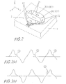
- Fig. 2 illustrates an example of a pattern of magnetisation in which only a magnetic film 2 is shown on the substrate 1 and other parts are removed for the sake of simplicity.
- a plurality of magnetic domains are formed divided by domain walls, each domain having a different direction of magnetisation.
- the magnetic film has a finite length in the Y-direction, which causes a demagnetisation field in the magnetic film and that, in order to reduce the magnetostatic energy caused by the demagnetisation field, flux closure domains are generated in the magnetic film.
- a 180° domain wall 201 is formed between adjacent main domains 21, and a 90° domain wall is formed between flux closure domain 22 and a main domain 21.
- Figs. 3(a) and 3(b) show examples of a reproduced signal waveform from the above type of magnetic head. "Wiggles” are observed in a trailing portion of the waveform in Fig. 3(a), and "popcorn” is observed in a random portion of the waveform in Fig. 3(b).
- Japanese Unexamined Patent Publication Tokukai-Hei 2-312005 discloses a heat-treatment method, in which a magnetic head subassembly composed of magnetic films, a coil, etc., is subjected to a heat treatment at 270 to 400°C before forming a protective layer 7 (shown in Fig. 1(b)).
- this method cannot always eliminate such noise.
- a permalloy (NiFe) layer is used as the magnetic film and its magnetostriction coefficient ⁇ is positive, noise reduction cannot be expected.
- EP-A-0 353 911 discloses a magnetic head according to the preamble of accompanying claim 1.
- the magnetic films of this head have magnetic domains in a stripe pattern arranged substantially parallel to the Y-axis in an orthogonal co-ordinate system where the magnetic films lie in the XY plane, and the X-axis is coincident with a centre line dividing the films into two symmetrical parts. Thereby the formation of contour domains in the XY plane is avoided.
- a magnetic head comprising a substrate, upper and lower magnetic films forming a magnetic circuit on the substrate, and a coil surrounding the magnetic circuit and located between the upper and lower magnetic films; characterised in that the magnetic films have both an in-plane magnetic anisotropy, parallel to the magnetic film surface, and a perpendicular magnetic anisotropy, perpendicular to the magnetic film surface.
- An embodiment of the present invention can provide a magnetic head having reduced susceptibility to spurious and transient noise pulses in a reproduced signal during a read operation, and which therefore is useful for applications requiring high reliability.
- An embodiment of the present invention has no particular structural difference from the structure described with reference to Figs. 1(a) and 1(b), and therefore the same reference numerals are used in the following description and detailed explanation of the structure is omitted.
- Particular features of the invention relate to magnetic anisotropy given to the magnetic films.
- An improved magnetic head can be realised by giving a perpendicular magnetic anisotropy to the magnetic films together with an in-plane magnetic anisotropy, as will become clear from the following explanation.
- a perpendicular (Z-axis) magnetic anisotropy is given to the magnetic films 2 by utilising a magnetostriction effect, and particularly in this embodiment, an inverse magnetostriction effect is utilised.
- magnetostriction effect an inverse magnetostriction effect is utilised.
- magnetic film(s) is used to denote both upper and lower magnetic films 2a and 2b, and each magnetic film is a single layer of magnetic material (see Fig. 1(a)).
- a magnetic field is applied in the Y-direction, and the proportion of nickel (Ni) contained in the permalloy (NiFe) film is controlled such that a magnetostriction coefficient ⁇ is kept negative.
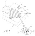
- Fig. 4 shows a magnetic domain configuration of the magnetic film in accordance with this embodiment, shown partly enlarged.
- Hp and Hv denote a direction of an in-plane magnetic anisotropy and a perpendicular magnetic anisotropy respectively.
- a plurality of parallel magnetic domains are formed divided by parallel domain walls. Magnetisations in two adjacent domains 20 are shown by arrows M1 and M2 in the enlarged view as examples and, as shown, each has both in-plane (Y-direction) and perpendicular (Z-direction) components of magnetic anisotropy.
- the above domain structure has been confirmed by the known Bitter method and'by observation of the Kerr effect.
- each domain has a perpendicular component whose direction is opposite to the perpendicular component of the adjacent magnetic domains. Magnetisation in two adjacent domains, each having a width (in the X-direction) of about 2 ⁇ m, are formed as if they form a closed magnetic path. Therefore, contour domains 22 such as shown in Fig. 2 can be avoided.
- Fig. 5 shows the amount of measured "popcorn" noise versus temperature during a sputtering or plating process of the magnetic film.
- the measured stress amount corresponding to the temperature data is shown on the upper side of the abscissa in Fig. 5.
- the stress generated in a magnetic film subjected to a heat-treatment is a tensile force, therefore it has a positive value.
- Fig. 5 shows the amount of measured "popcorn" noise versus temperature during a sputtering or plating process of the magnetic film.
- Fig. 6 shows the variation in noise when the ratio of perpendicular anisotropy Hv to in-plane anisotropy Hp is changed.
- the perpendicular anisotropy Hv is not sufficient to reduce the noise.
- the perpendicular anisotropy should satisfy the condition of Hv/Hp > 1.5.
- the necessary condition of Hv/Hp > 1.5 can be rewritten in the form ⁇ x ⁇ , which is shown in Fig. 7.
- the necessary condition of Hv/Hp > 1.5 corresponds to ⁇ x ⁇ ⁇ -7.5 x 10³ erg/cm3 (-750 ⁇ J/cm3).
- the noise data shown in Figs. 5 and 6 is the number of detected counts (occurrences) of "popcorn" noise over 6,250 cycles of a write and read (detection) test.
- Fig. 8 illustrates schematically a time chart of a single test cycle.
- waveform trace (a) shows a write current applied to a coil of magnetic head, the write cycle having a 1.6 ms period.
- a read period for noise begins after a 20 ⁇ s pause time and continues until the next write period.
- Any "popcorn" noise greater than a threshold value of 40 ⁇ V is detected as shown by trace (b) and generates a signal (c) for a counter circuit.
- a second embodiment of the present invention utilises cobalt alloy for forming the magnetic films 2.
- the magnetic film is formed by sputtering cobalt alloy such as CoZrCr, CoZr, CoZrNb and CoZrMo, and in addition a magnetic field is applied in the Y-direction during the sputtering process.
- the finished subassembly is subjected to a heat treatment at a temperature higher than 250°C, whilst simultaneously applying a magnetic field in the Z-direction (perpendicular to the film surface) having a strength of a few hundreds Oe (a few tens kAm ⁇ 1).
- Fig. 9(a) shows the BH curve for a magnetic head produced without applying a Z-direction magnetic field during the above heat treatment
- Fig. 9(b) shows the same thing when the Z-direction magnetic field is applied.
- the BH curve of Fig. 9(a) has a desirable shape, considering the magnetic characteristic of the magnetic head in isolation; however, the noise characteristic is unsatisfactory.
- the BH curve of Fig. 9(b) in accordance with the second embodiment of the invention clearly shows that a perpendicular magnetic anisotropy (perpendicular to the magnetic film surface) is induced in the magnetic films (induced magnetic anisotropy).
- the magnetic heads have been tested and found to have an improved noise characteristic as in the first embodiment.
- a third embodiment of the present invention utilises a perpendicular magnetic anisotropy which appears in a crystalline structure of magnetic material.
- Permalloy NiFe alloy
- K anisotropy constant K
- the crystalline magnetic anisotropy appears in the direction [111] of the permalloy crystal structure.
- a permalloy film is formed in such a way that the perpendicular to the film surface is coincident with the [111] direction, the film is given a perpendicular magnetic anisotropy (Z-direction) which reduces the occurrence of spurious and transient noise in the reproduced signal from the magnetic head.
- permalloy films are first formed by a sputtering or plating process, and the head subassembly thus formed is then subjected to a heat treatment above 300°C. This results in recrystallising the permalloy films so as to give them the desired crystalline magnetic anisotropy, namely with an anisotropic direction coincident with the perpendicular to the film surface.
- the magnetic head comprises a magnetic film having a perpendicular magnetic anisotropy together with an in-plane magnetic anisotropy.
- Magnetic domains in the magnetic film have a tendency to form a closed path of magnetisation by movements of the neighbouring magnetic domains.
- the closed path is formed not only in the surface direction of the magnetic film but also in the thickness direction thereof.
- the magnetic structure in the thickness direction shows a fine changing domain structure, which avoids the occurrence of large flux contour domains in the XY-plane, such as that labelled 22 in Fig. 2.
Landscapes
- Engineering & Computer Science (AREA)
- Manufacturing & Machinery (AREA)
- Magnetic Heads (AREA)
Claims (13)
- Ein Magnetkopf, umfassend ein Substrat (1), obere und untere Magnetfilme (2, 2a, 2b), die einen magnetischen Kreis auf dem Substrat bilden, und eine Wicklung (3), die den magnetischen Kreis umgibt und sich zwischen den oberen und unteren Magnetfilmen (2, 2a, 2b) befindet;
dadurch gekennzeichnet, daß die Magnetfilme (2, 2a, 2b) sowohl eine magnetische Anisotropie (Hp) in der Ebene, parallel zu der Magnetfilmoberfläche, als auch eine senkrechte magnetische Anisotropie (Hv), senkrecht zu der Magnetfilmoberfläche, aufweisen. - Ein Magnetkopf nach Anspruch 1, worin die Richtung der magnetischen Anisotropie (Hp) in der Ebene mit der Y-Richtung in einem orthogonalen Koordinatensystem übereinstimmt, wo die Magnetfilme (2, 2a, 2b) in der XY-Ebene liegen und die X-Achse mit einer die Magnetfilmoberfläche in zwei symmetrische Teile teilenden Linie übereinstimmt.
- Ein Magnetkopf nach Anspruch 2, worin die Magnetfilme (2, 2a, 2b) eine Vielzahl magnetischer Domänen (20) aufweisen, jede magnetische Domäne eine Streifenform aufweisend und im wesentlichen parallel zu der Y-Achse angeordnet, wodurch eine Bildung von Konturdomänen in der XY-Ebene vermieden wird.
- Ein Magnetkopf nach Anspruch 3, worin die senkrechten magnetischen Anisotropiekomponenten benachbarter magnetischer Domänen (20) entgegengesetzte Richtungen haben.
- Ein Magnetkopf nach irgendeinem vorhergehenden Anspruch, worin die senkrechte magnetische Anisotropie (Hv) größer als das 1,5-fache der magnetischen Anisotropie (Hp) in der Ebene ist.
- Ein Magnetkopf nach irgendeinem vorhergehenden Anspruch, worin die Magnetfilme (2, 2a, 2b) aus einer NiFe-Legierung hergestellt sind und die senkrechte magnetische Anisotropie (Hv) durch einen inversen Magnetostriktionseffekt gegeben ist, wobei ein Produkt eines Magnetostriktionskoeffizienten (λ) des Magnetfilms und einer Beanspruchung (σ), die darauf angewandt wird, geringer als -7,5 x 10³ erg/cm³ (-750 µJ/cm³) ist.
- Ein Magnetkopf nach irgendeinem der Ansprüche 1 bis 5, worin die Magnetfilme (2, 2a, 2b) aus einer Kobaltlegierung hergestellt sind und- die senkrechte magnetische Anisotropie (Hv) eine induzierte magnetische Anisotropie ist, die durch Anlegen eines zu der Magnetfilmoberfläche senkrechten Magnetfeldes erzeugt wird.
- Ein Magnetkopf nach irgendeinem der Ansprüche 1 bis 5, worin die Magnetfilme (2, 2a, 2b) aus einer NiFe-Legierung hergestellt sind und die senkrechte magnetische Anisotropie (Hv) eine kristalline magnetische Anisotropie ist, die durch Bilden der Magnetfilme erzeugt wird, so daß die Senkrechte dazu mit der [111]-Achse der NiFe-Kristallstruktur übereinstimmt.
- Ein Magnetkopf nach Anspruch 6, worin der Nickelgehalt der NiFe-Legierung größer als etwa 83,4 % ist.
- Ein Magnetkopf nach Anspruch 7, worin die Kobaltlegierung aus CoZrCr, CoZr, CoZrNb und CoZrMo ausgewählt ist.
- Ein Magnetkopf nach Anspruch 8, worin die Magnetfilme (2, 2a, 2b) durch Ablagern/Galvanisieren einer NiFe-Legierung und anschließendes Rekristallisieren der NiFe-Schicht gebildet werden.
- Ein Magnetkopf nach irgendeinem vorhergehenden Anspruch, worin jeder der oberen und unteren Magnetfilme (2, 2a, 2b) eine einfache Schicht eines magnetischen Materials ist.
- Ein Magnetkopf nach irgendeinem vorhergehenden Anspruch, worin die Magnetfilme (2, 2a, 2b) geformt sind, um einen schmalen Teil mit einer Lücke (6) bei einem Ende des magnetischen Kreises zum Wechselwirken mit einem Aufzeichnungsmedium zu bilden, und worin die Wicklung (3) in einer zwischen den oberen und unteren Magnetfilmen vorgesehenen Isolationsschicht (4) beerdigt ist.
Applications Claiming Priority (2)
| Application Number | Priority Date | Filing Date | Title |
|---|---|---|---|
| JP27451390 | 1990-10-12 | ||
| JP274513/90 | 1990-10-12 |
Publications (3)
| Publication Number | Publication Date |
|---|---|
| EP0480324A2 EP0480324A2 (de) | 1992-04-15 |
| EP0480324A3 EP0480324A3 (en) | 1993-06-16 |
| EP0480324B1 true EP0480324B1 (de) | 1996-05-29 |
Family
ID=17542748
Family Applications (1)
| Application Number | Title | Priority Date | Filing Date |
|---|---|---|---|
| EP91116953A Expired - Lifetime EP0480324B1 (de) | 1990-10-12 | 1991-10-04 | Dünnfilmmagnetkopf |
Country Status (6)
| Country | Link |
|---|---|
| US (1) | US5187628A (de) |
| EP (1) | EP0480324B1 (de) |
| JP (1) | JP2533255B2 (de) |
| KR (1) | KR950014893B1 (de) |
| CA (1) | CA2053330C (de) |
| DE (1) | DE69119860T2 (de) |
Families Citing this family (11)
| Publication number | Priority date | Publication date | Assignee | Title |
|---|---|---|---|---|
| US5736921A (en) * | 1994-03-23 | 1998-04-07 | Sanyo Electric Co., Ltd. | Magnetoresistive element |
| US5585198A (en) * | 1993-10-20 | 1996-12-17 | Sanyo Electric Co., Ltd. | Magnetorsistance effect element |
| JPH07134804A (ja) * | 1993-09-17 | 1995-05-23 | Fujitsu Ltd | 記録再生装置及び記録再生方法 |
| JPH08130337A (ja) * | 1994-09-09 | 1996-05-21 | Sanyo Electric Co Ltd | 磁気抵抗素子及びその製造方法 |
| JP2000020916A (ja) | 1998-07-01 | 2000-01-21 | Hitachi Ltd | 誘導型薄膜磁気ヘッド |
| US6233116B1 (en) * | 1998-11-13 | 2001-05-15 | Read-Rite Corporation | Thin film write head with improved laminated flux carrying structure and method of fabrication |
| US6221218B1 (en) | 1998-11-23 | 2001-04-24 | Read-Rite Corporation | Method of forming an inductive write head for magnetic data storage media |
| US6190764B1 (en) | 1998-11-23 | 2001-02-20 | Read-Rite Corporation | Inductive write head for magnetic data storage media |
| US8470463B2 (en) | 2011-04-22 | 2013-06-25 | Seagate Technology Llc | Magnetic shield with in-plane anisotropy |
| US8675315B2 (en) | 2011-07-29 | 2014-03-18 | Seagate Technology Llc | Magnetic sensor with anisotropic liner |
| US8896971B2 (en) | 2012-08-21 | 2014-11-25 | Seagate Technology Llc | Aligned magnetic insulating feature |
Family Cites Families (6)
| Publication number | Priority date | Publication date | Assignee | Title |
|---|---|---|---|---|
| US4944805A (en) * | 1987-09-10 | 1990-07-31 | Fuji Photo Film Co., Ltd. | Method of heat treatment amorphous soft magnetic film layers to reduce magnetic anisotropy |
| JPH0198110A (ja) * | 1987-10-12 | 1989-04-17 | Mitsubishi Electric Corp | 薄膜磁気ヘツドの製造方法 |
| DE3888680T2 (de) * | 1987-12-04 | 1994-09-08 | Digital Equipment Corp | Lamellierte pole für magnetköpfe. |
| US5089334A (en) * | 1988-08-03 | 1992-02-18 | Digital Equipment Corporation | Flux spreading thin film magnetic devices |
| US5085935A (en) * | 1988-08-03 | 1992-02-04 | Digital Equipment Corporation | Flux spreading thin film magnetic devices |
| JPH063644B2 (ja) * | 1989-05-27 | 1994-01-12 | ティーディーケイ株式会社 | 薄膜磁気ヘッドにおけるパルス状ノイズ防止方法 |
-
1991
- 1991-09-26 US US07/765,742 patent/US5187628A/en not_active Expired - Lifetime
- 1991-10-04 DE DE69119860T patent/DE69119860T2/de not_active Expired - Fee Related
- 1991-10-04 EP EP91116953A patent/EP0480324B1/de not_active Expired - Lifetime
- 1991-10-09 JP JP3261927A patent/JP2533255B2/ja not_active Expired - Fee Related
- 1991-10-11 KR KR1019910017839A patent/KR950014893B1/ko not_active Expired - Fee Related
- 1991-10-11 CA CA002053330A patent/CA2053330C/en not_active Expired - Fee Related
Non-Patent Citations (2)
| Title |
|---|
| P.Ciureanu, H.Gavrila Magnetic Heads for Digital Recording 1990, p.505-510. * |
| transducers' * |
Also Published As
| Publication number | Publication date |
|---|---|
| US5187628A (en) | 1993-02-16 |
| JPH05266423A (ja) | 1993-10-15 |
| EP0480324A2 (de) | 1992-04-15 |
| CA2053330C (en) | 1996-02-20 |
| CA2053330A1 (en) | 1992-04-13 |
| JP2533255B2 (ja) | 1996-09-11 |
| DE69119860T2 (de) | 1996-10-02 |
| EP0480324A3 (en) | 1993-06-16 |
| DE69119860D1 (de) | 1996-07-04 |
| KR950014893B1 (ko) | 1995-12-16 |
| KR920008677A (ko) | 1992-05-28 |
Similar Documents
| Publication | Publication Date | Title |
|---|---|---|
| US5014147A (en) | Magnetoresistive sensor with improved antiferromagnetic film | |
| US5379172A (en) | Laminated leg for thin film magnetic transducer | |
| US6063512A (en) | Soft magnetic thin film having Co, Ni and Fe as main ingredients, method of manufacturing the same and magnetic head and magnetic storage unit using the soft magnetic thin film | |
| JP2857286B2 (ja) | 磁気抵抗効果型薄膜磁気ヘッド | |
| US20060164759A1 (en) | Magnetic head | |
| JPH02240813A (ja) | 磁気トランスデユーサのラツピング制御装置 | |
| EP0480324A2 (de) | Dünnfilmmagnetkopf | |
| EP0281931B1 (de) | Magnetkopf | |
| US6150046A (en) | Combination magnetoresistive/inductive thin film magnetic head and its manufacturing method | |
| EP0288765A2 (de) | Magnetoresistiver Sensor mit antiferromagnetischem Film von gemischter Phase | |
| US5776537A (en) | Method of characterizing exchange coupling for magnetoresistive sensor | |
| KR100272782B1 (ko) | 복합형 판독/기록 박막자기헤드 및 그 제조 방법 | |
| KR100263869B1 (ko) | 복합형 박막 자기헤드 및 그 제조방법 | |
| EP0353885B1 (de) | Senkrechte Anisotropie in Dünnfilmvorrichtungen | |
| US4943883A (en) | Quarternary amorphous magnetic alloy thin film and magnetic head including same | |
| US5687044A (en) | Magnetoresistive head with micro-crystallite shielding layer | |
| EP0694911B1 (de) | Magnetowiderstandsmagnetkopf für Aufzeichnung und Wiedergabe | |
| EP0444903A2 (de) | Dünnfilm-Magnetkopf für senkrechte Aufzeichnung und Wiedergabe | |
| JPH08330645A (ja) | 磁気検出素子 | |
| Gaud et al. | A new silicon integrated head for high density magnetic tape recording | |
| JPS6111916A (ja) | 磁気ヘツド検査方法 | |
| Lee et al. | Demagnetization-free longitudinal recording on flexible thin film metal media | |
| JPH03109703A (ja) | 軟磁性薄膜及び磁気ヘッド | |
| Chen | Thin film magnetic recording | |
| JPH03268214A (ja) | ライト後ノイズを制御した薄膜磁気ヘッド |
Legal Events
| Date | Code | Title | Description |
|---|---|---|---|
| PUAI | Public reference made under article 153(3) epc to a published international application that has entered the european phase |
Free format text: ORIGINAL CODE: 0009012 |
|
| AK | Designated contracting states |
Kind code of ref document: A2 Designated state(s): DE FR GB |
|
| PUAL | Search report despatched |
Free format text: ORIGINAL CODE: 0009013 |
|
| AK | Designated contracting states |
Kind code of ref document: A3 Designated state(s): DE FR GB |
|
| 17P | Request for examination filed |
Effective date: 19930730 |
|
| 17Q | First examination report despatched |
Effective date: 19950228 |
|
| RBV | Designated contracting states (corrected) |
Designated state(s): DE FR |
|
| GRAH | Despatch of communication of intention to grant a patent |
Free format text: ORIGINAL CODE: EPIDOS IGRA |
|
| GRAA | (expected) grant |
Free format text: ORIGINAL CODE: 0009210 |
|
| AK | Designated contracting states |
Kind code of ref document: B1 Designated state(s): DE FR |
|
| REF | Corresponds to: |
Ref document number: 69119860 Country of ref document: DE Date of ref document: 19960704 |
|
| ET | Fr: translation filed | ||
| PLBE | No opposition filed within time limit |
Free format text: ORIGINAL CODE: 0009261 |
|
| STAA | Information on the status of an ep patent application or granted ep patent |
Free format text: STATUS: NO OPPOSITION FILED WITHIN TIME LIMIT |
|
| 26N | No opposition filed | ||
| PGFP | Annual fee paid to national office [announced via postgrant information from national office to epo] |
Ref country code: DE Payment date: 20050929 Year of fee payment: 15 |
|
| PGFP | Annual fee paid to national office [announced via postgrant information from national office to epo] |
Ref country code: FR Payment date: 20051010 Year of fee payment: 15 |
|
| PG25 | Lapsed in a contracting state [announced via postgrant information from national office to epo] |
Ref country code: DE Free format text: LAPSE BECAUSE OF NON-PAYMENT OF DUE FEES Effective date: 20070501 |
|
| REG | Reference to a national code |
Ref country code: FR Ref legal event code: ST Effective date: 20070629 |
|
| PG25 | Lapsed in a contracting state [announced via postgrant information from national office to epo] |
Ref country code: FR Free format text: LAPSE BECAUSE OF NON-PAYMENT OF DUE FEES Effective date: 20061031 |