EP0480398A2 - Bilderzeugungsgerät mit Aufzeichnungsmaterial-Transportmitteln - Google Patents
Bilderzeugungsgerät mit Aufzeichnungsmaterial-Transportmitteln Download PDFInfo
- Publication number
- EP0480398A2 EP0480398A2 EP91117207A EP91117207A EP0480398A2 EP 0480398 A2 EP0480398 A2 EP 0480398A2 EP 91117207 A EP91117207 A EP 91117207A EP 91117207 A EP91117207 A EP 91117207A EP 0480398 A2 EP0480398 A2 EP 0480398A2
- Authority
- EP
- European Patent Office
- Prior art keywords
- recording material
- transfer
- sheet
- image
- image forming
- Prior art date
- Legal status (The legal status is an assumption and is not a legal conclusion. Google has not performed a legal analysis and makes no representation as to the accuracy of the status listed.)
- Granted
Links
Images


Classifications
-
- G—PHYSICS
- G03—PHOTOGRAPHY; CINEMATOGRAPHY; ANALOGOUS TECHNIQUES USING WAVES OTHER THAN OPTICAL WAVES; ELECTROGRAPHY; HOLOGRAPHY
- G03G—ELECTROGRAPHY; ELECTROPHOTOGRAPHY; MAGNETOGRAPHY
- G03G15/00—Apparatus for electrographic processes using a charge pattern
- G03G15/01—Apparatus for electrographic processes using a charge pattern for producing multicoloured copies
- G03G15/0105—Details of unit
- G03G15/0131—Details of unit for transferring a pattern to a second base
-
- G—PHYSICS
- G03—PHOTOGRAPHY; CINEMATOGRAPHY; ANALOGOUS TECHNIQUES USING WAVES OTHER THAN OPTICAL WAVES; ELECTROGRAPHY; HOLOGRAPHY
- G03G—ELECTROGRAPHY; ELECTROPHOTOGRAPHY; MAGNETOGRAPHY
- G03G15/00—Apparatus for electrographic processes using a charge pattern
- G03G15/01—Apparatus for electrographic processes using a charge pattern for producing multicoloured copies
- G03G15/0142—Structure of complete machines
- G03G15/0178—Structure of complete machines using more than one reusable electrographic recording member, e.g. one for every monocolour image
- G03G15/0194—Structure of complete machines using more than one reusable electrographic recording member, e.g. one for every monocolour image primary transfer to the final recording medium
-
- G—PHYSICS
- G03—PHOTOGRAPHY; CINEMATOGRAPHY; ANALOGOUS TECHNIQUES USING WAVES OTHER THAN OPTICAL WAVES; ELECTROGRAPHY; HOLOGRAPHY
- G03G—ELECTROGRAPHY; ELECTROPHOTOGRAPHY; MAGNETOGRAPHY
- G03G2215/00—Apparatus for electrophotographic processes
- G03G2215/01—Apparatus for electrophotographic processes for producing multicoloured copies
- G03G2215/0103—Plural electrographic recording members
- G03G2215/0119—Linear arrangement adjacent plural transfer points
Definitions
- the present invention relates to an image forming apparatus for forming an image on a recording material carried on a recording material carrying means, more particularly to an image forming apparatus for forming a multi-color image on the recording material.
- a color copying machine or the like having plural image forming stations wherein different color images are formed by the respective image forming stations, and the images are superposedly transferred onto the recording material in the form of a transfer sheet.
- PA, PB, PC and PD are black, yellow, magenta and cyan image forming stations.
- a recording material carrying means in the form of a transfer material conveying belt 200 is disposed which carries the transfer sheet P and which is movable along an endless path.
- Each of the image forming stations PA, PB, PC or PD has an image bearing member 100a, 100b, 100c or 100d, around which there are disposed a latent image forming station 101a, 101b, 101c and 101d, a developing station 102a, 102b, 102c or 102d, an image transfer station 103a, 103b, 103c or 103d, a cleaning station 104a, 104b, 104c or 104d.
- the developing stations 102a, 102b, 102c and 102d contain different color developers.
- the transfer stations 103a, 103b, 103c and 103d comprise image transfer means disposed within the transfer belt path.
- the transfer sheet P is fed out of a sheet cassette 110 and is attracted on the transfer belt 200. It is passed through the image forming stations PA, PB, PC and PD so that the color images formed on the photosensitive drums 100a, 100b, 100c and 100d are sequentially transferred onto the transfer sheet P by the transfer stations 103a, 103b, 103c and 103d, by which a full (four) color image is formed on the transfer sheet P.
- the transfer material conveying belt 200 comprises a film sheet of polyethylene terephthalate resin, polyvinylidene fluoride resin or another dielectric resin material, having opposite ends which are overlaid and bonded into an endless film sheet. Therefore, it comprises a seam 200a.
- the seam portion 200a have a different nature from the other portion, and therefore, if an image is transferred onto the transfer sheet P through the seam 200a, the transfer action is not satisfactory with the result of defective images. In view of this, when the transfer sheet P is supported on the transfer material conveying belt 200, the transfer sheet P is supplied to the transfer belt 200 so that it is not supported on the seam 200a.
- the transfer sheet P1 is supplied to the position 40 mm away from the seam 200a, for example. If the next transfer sheet P2 is supplied to the position 70 mm away from the trailing edge of the first transfer sheet P1, the transfer sheet P2 is partly on the seam 200a.
- a transfer sheet of A4 size (210 mm in the belt moving direction) is supplied to the transfer belt 200 having a circumferential length of 800 mm.
- three transfer sheets P1, P2 and P3 are supplied to the belt 200. Even in this case, none of the transfer sheets is on the seam 200a of the belt 200, and the sufficient sheet intervals (approximately 56 mm in this case) can be assured.
- Figure 1 shows a supply of a transfer sheet to a transfer material conveying belt in an image forming apparatus according to an embodiment of the present invention.
- Figure 2 shows the same in a modified image forming apparatus according to an embodiment of the present invention.
- Figure 3 is a sectional view of the image forming apparatus.
- Figure 4 is a sectional view of a major part of an image forming apparatus according to a second embodiment of the present invention.
- Figure 5 is a sectional view of a conventional image forming apparatus.
- Figure 6 shows the supply of the transfer belt to the transfer material conveying belt in the image forming apparatus.
- Figure 7 is a top plan view illustrating the position of the transfer sheet attracted on the transfer belt.
- Figure 8 illustrates backside contamination of the transfer material.
- Figure 9 Shows sequential operations of the image forming apparatus.
- Figure 10 is a first block diagram for the image forming apparatus.
- Figure 11 illustrates a home position detecting system for the transfer belt.
- Figure 12 is a second block diagram for the image forming apparatus.
- FIG 3 there is shown an image forming apparatus according to this embodiment, wherein PA, PB, PC and PD designate black, yellow, magenta and cyan image forming stations, which are arranged on a horizontal line. Below the image forming stations PA, PB, PC and PD, there is disposed a transfer material conveying belt 10 (transfer material carrying means) movable along an endless path.
- a transfer material conveying belt 10 transfer material carrying means
- the image forming stations PA, PB, PC and PD have photosensitive drums 1a, 1b, 1c and 1d, respectively.
- a charger 2a, 2b, 2c or 2d Around each of the photosensitive drums 1a, 1b, 1c and 1d, there are disposed a charger 2a, 2b, 2c or 2d, a scanner unit 3a, 3b, 3c or 3d, a developing device 4a, 4b, 4c or 4d, an image transfer charger 5a, 5b, 5c or 5d, and a cleaning device 6a, 6b, 6c or 6d.
- the transfer charger 5a, 5b, 5c or 5d is disposed in the transfer material conveying belt 10 travel.
- the transfer charger 5a, 5b, 5c or 5d is effective to transfer the toner image from the photosensitive drum 1a, 1b, 1c or 1d onto the transfer sheet P.
- the transfer material conveying belt 10 is made of polyurethane resin, PVdF resin, PET resin, polycarbonate resin, polyether sulfone resin, polyurethane resin or another dielectric resin material.
- the transfer belt 10 is in the form of a film having opposite ends which are bonded by ultrasonic wave fusing means or the like into an endless film. It is rotated at a constant speed (100 mm/sec, for example) in the direction indicated by an arrow in Figure 3 by driving rollers 11 and 11.
- Designated by a reference numeral 12 is a tension roller.
- the transfer belt 10 electrostatically attracts the transfer sheet P and carries it through the image forming stations PA, PB, PC and PD, so that the transfer sheet P receives images in the respective image forming stations. After receiving the images, the transfer sheet P is subjected to the discharging operation, and is separated from the transfer belt 10 by a separation charger 13 disposed at a sheet discharge side of the transfer belt 10.
- the image forming operation of the image forming apparatus will be described, taking the black color image forming station PA as an example.
- the photosensitive drum 1a is uniformly charged by a charger 2a and is exposed to image light L for the black image through a scanner unit 3a, so that an electrostatic latent image is formed on the photosensitive drum 1a.
- the electrostatic latent image is moved to the developing device 4a having the black toner by the rotation of the photosensitive drum 1a.
- the developing device 4a visualizes the latent image into a black toner image.
- the toner image is transferred onto the transfer sheet P on the transfer belt 10 by a transfer charger 5a at an image formation position, that is, the transfer position where the photosensitive drum 1a and the transfer charger 5a are faced to each other through the belt 10.
- the photosensitive drum 1a is cleaned by a cleaning device 5a so that the residual toner is removed therefrom, and the photosensitive drum 1a is prepared for the next image forming operation.
- the photosensitive member In the yellow image forming station PA, the photosensitive member is uniformly charged and is exposed to yellow image light L in the similar manner but at a timed relation with the image forming operation in the former image forming station PA.
- the latent image is developed into a yellow toner image by the developing device 4b containing the yellow toner.
- the yellow toner image is superposedly transferred onto the transfer sheet P already having the black toner and conveyed by the belt 10, at an image formation station, that is, an image transfer position where the photosensitive drum 1b and the transfer charger 5b are faced to each other.
- magenta and cyan images are formed in the image forming station PC and PD, so that magenta and cyan toner images are formed and transferred onto the transfer sheet P.
- magenta and cyan toner images are formed and transferred onto the transfer sheet P.
- four full-color toner image is formed on the transfer sheet P.
- the transfer sheet P is singled out by the pick-up roller 15 from the sheet cassette 14, and is supplied to the registration rollers 16, which further feed the sheet to the transfer material in synchronism with the drum.
- the transfer sheet P is attracted on the transfer belt 10 by the attraction charger 18 and the attraction roller 19, and is carried through the four image forming stations PA, PB, PC and PD, so that four color toner images are superposedly transferred onto the transfer sheet P.
- the transfer sheet P After receiving the images, the transfer sheet P is subjected to the operation of the separation charger 13 adjacent a discharge side end of the belt 19, and therefore, is separated from the transfer belt 10. Then, it is conveyed to the fixing device 13 where the toner image thereon is fixed into a permanent image.
- the transfer belt 10 has a seam 10a. If the transfer sheet P is on the seam 10a, the toner image is not properly transferred onto the transfer sheet P at the position on the seam 10a. In view of this, when the transfer sheet P is supplied to the transfer belt 10, it is avoided that the transfer sheet P is on the seam 10a.
- the transfer sheet P is unable to be supplied to the transfer belt 10 with a predetermined sheet interval (the interval from the trailing edge of the transfer sheet to the leading edge of the next transfer sheet on the belt 10) in a continuous copying or printing mode, when a maximum size transfer sheet P is used.
- the interval a is preferably not less than 50 mm.
- the transfer sheet P1 is supplied to the transfer material conveying belt 10 to the position 40 mm away from the seam 10a so as to avoid the seam 10a, as shown in Figure 1A. Then, as shown in Figure 1B, the next transfer sheet P2 is supplied with an interval of 70 mm from the trailing edge of the first transfer sheet P1. Then, the second transfer sheet P2 is not on the seam 10a of the belt 10.
- the efficiency K of use of the transfer belt 10 is:
- the transfer material conveying belt 10 is efficiently used.
- the number of image formations on the transfer sheets P per unit time is increased in the continuous operation mode.
- the transfer belt 10 is usable not only with the A3 size sheets but also with ledger size (17x11 inch) relatively frequency used in U.S.A., if the sheet interval a is 58.2 mm in the continuous mode with sufficiently high use efficiency K of the transfer belt.
- the sheet interval a is set to approximately 50 mm (minimum limit), and the sheet interval is approximately one half the sheet interval for the maximum size of the transfer sheet, by properly determining the total length L of the transfer belt 10.
- a transfer drum replaces the transfer material carrying belt in the first embodiment.
- outside the transfer drum 30 there are disposed black, yellow, magenta and cyan image forming stations PA, PB, PC and PD to constitute a multi-color image forming apparatus.
- a sheet supply cassette 14 At the sheet feeding side of the transfer drum 30, there are disposed a sheet supply cassette 14, a sheet pick-up roller 15, registration rollers 16, an attraction charger 18 and an attraction assisting roller 19.
- a separation charger 20 At the sheet discharge side of the transfer drum 30, there are disposed a separation charger 20, a separating pawl 21 and an image fixing device 17.
- the transfer sheet P is supplied to the transfer drum 30 by the sheet cassette 14, the pick-up roller 15 and the registration roller 16 and is charged by an attraction charger 18 and is attracted and supported on the outer surface of the transfer drum 30 by the grounded attraction assisting roller 19.
- the black, yellow, magenta and cyan toner images are superposedly transferred onto the transfer sheet P by image forming stations PA, PB, PC and PD.
- the transfer sheet P is discharged by the separation charger 20, and is separated from the transfer drum 30 by a separation pawl 21. It is then fed to the fixing device 17 where the superposed toner images are heated and fixed on the transfer sheet P so that they are fused and mixed into a full color image.
- the outer surface of the transfer drum 30 is provided by a film sheet 31 (transfer material carrying member) made of the same material as the transfer belt 10 of the first embodiment.
- the sheet 31 is in the form of an endless sheet with a seam 31a and mounted on opposing rings made of metal or the like.
- the transfer sheet P is attracted and supported on the film sheet 31. It is therefore desirable that the transfer sheet P is supplied to the transfer drum 30 in the manner that the transfer sheet P is not on the seam 31a.
- L n( l ⁇ + a) where l is a length of the maximum usable transfer sheet P measured in the direction of the transfer drum 30 rotation, a is a sheet interval, and n is an integer.
- the film sheet 31 can be efficiently used, and in the continuous mode, the number of image formations on the transfer sheet P per unit time is increased.
- FIG. 7 shows the positions of the transfer sheet P on the transfer belt 10 in this embodiment.
- the transfer belt 10 is expanded.
- the sheet interval a is 110 mm which is slightly long.
- the position of the transfer sheet attracted on the transfer belt 10 is the same, and therefore, the backside of the transfer material is not contaminated.
- the contamination at the back of the transfer sheet will be described.
- a second transfer sheet is not always supported on the transfer belt exactly at the same position as the first transfer sheet. It is possible that the second sheet is supported with deviation from the first sheet supported position with some overlapping. Because of the toner attraction in the sheet interval region, which will be described hereinafter, the second and subsequent transfer materials are contaminated at the back sides thereof.
- the causes of the backside contamination are as follows:
- the cleaning device 6 (6a - 6d) has the function of removing the residual toner from the photosensitive drum 1 and collect it however, the toner removed from the photosensitive drum is not completely collected in the container of the cleaning device, but a slight amount of the toner scatters. These toner particles fall on the transfer belt 10 and causes the backside contamination.
- control is effected during the continuous image forming operation so that the transfer sheets are always supported on the transfer belt at the constant position, by properly setting the belt circumferential length and the sheet interval distance. Therefore, the backside of the transfer material is not contaminated.
- the interval a is dependent on the size of the transfer sheet. However, in the continuous mode, the sheet interval a is always constant (110 mm for A4 size as shown in Table 1). The time interval between adjacent transfer sheets are constant, and therefore, the operator is not threatened by the sheet discharge at different intervals. In addition, the sequential control for the apparatus may be simplified.
- Figure 9 shows the sequential operations of the apparatus in the continuous mode when the size of the transfer sheet is A4.
- FIG 10 is a block diagram of the control system for the image forming apparatus of this embodiment.
- the sequential operations are controlled by CPU 501, and the sequential operations are instructed by ROM 502.
- Various elements in the main assembly such as the sheet pick-up roller, registration rollers, photosensitive drum motor, a high voltage source for supplying electric power to the chargers, are controlled by the CPU 501 through a DC controller 506, D/A converter, I/O port.
- the operational timing is determined by counting pulse clocks produced by the transfer belt driving motor (pulse motor) 505 by a counter 503, and by referring the counts to ROM 502 through the CPU 501.
- the sheet interval distance corresponding to the size of the transfer material as defined in Table 1 is stored in a part of the ROM 502.
- the control is effected in the continuous mode that the positions of the transfer materials attracted on the transfer belt are at all times constant on the transfer belt.
- a light blocking plate 30 is provided to detect the home position of the transfer belt 10 by the photosensor 506 at every rotations. On the basis of the detection, the pulse clock from the belt driving motor 505 is reset for every one rotation of the transfer belt.
- Figures 11A and 11B show the detecting method.
- Figure 11A is a top plan view of the transfer belt 10, and Figure 11B is a partial sectional view thereof.
- the detecting means is an optical type using a photosensor, but it is not limiting, and the electric, magnetic or the like type is usable.
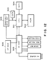
- Figure 12 is a block diagram in this embodiment.
- the pulse clock supplied from the belt driving motor 505 is counted by the counter 503, and the count is supplied to the CPU 501.
- the one full-rotation of the transfer belt 10 is discriminated.
- the start of the second period is discriminated.
- the counter 503 is reset upon detection of the home position by the sensor 506 irrespective of whether the count reaches the predetermined value X or not. Then, the count becomes "zero" , and the start of the second period is discriminated.
- the further accurate operational sequence can be used as compared with Figure 10 case.
- plural photosensitive drums are provided to form a full-color image on a recording material.
- the present invention is applicable to full-color or black- or white-image is formed with a single photosensitive drum.
- the present invention is applicable to an ink jet type apparatus using image forming stations PA, PB, PC and PD having ink jet recording heads.
- the images are directly formed on the sheet carried on the belt 10.
Landscapes
- Physics & Mathematics (AREA)
- General Physics & Mathematics (AREA)
- Electrostatic Charge, Transfer And Separation In Electrography (AREA)
- Color Electrophotography (AREA)
Applications Claiming Priority (4)
| Application Number | Priority Date | Filing Date | Title |
|---|---|---|---|
| JP2271637A JP2954314B2 (ja) | 1990-10-09 | 1990-10-09 | 画像形成装置 |
| JP271637/90 | 1990-10-09 | ||
| JP272147/90 | 1990-10-12 | ||
| JP2272147A JPH04149474A (ja) | 1990-10-12 | 1990-10-12 | 画像形成装置 |
Publications (3)
| Publication Number | Publication Date |
|---|---|
| EP0480398A2 true EP0480398A2 (de) | 1992-04-15 |
| EP0480398A3 EP0480398A3 (en) | 1992-10-14 |
| EP0480398B1 EP0480398B1 (de) | 1997-04-16 |
Family
ID=26549812
Family Applications (1)
| Application Number | Title | Priority Date | Filing Date |
|---|---|---|---|
| EP91117207A Expired - Lifetime EP0480398B1 (de) | 1990-10-09 | 1991-10-09 | Bilderzeugungsgerät mit Aufzeichnungsmaterial-Transportmitteln |
Country Status (3)
| Country | Link |
|---|---|
| US (1) | US5557383A (de) |
| EP (1) | EP0480398B1 (de) |
| DE (1) | DE69125680T2 (de) |
Cited By (1)
| Publication number | Priority date | Publication date | Assignee | Title |
|---|---|---|---|---|
| EP0603819A1 (de) * | 1992-12-22 | 1994-06-29 | Canon Kabushiki Kaisha | Bilderzeugungsgerät, welches ein Übertragungsmaterial tragendes Element aufweist |
Families Citing this family (4)
| Publication number | Priority date | Publication date | Assignee | Title |
|---|---|---|---|---|
| JP3513975B2 (ja) * | 1995-04-15 | 2004-03-31 | 富士ゼロックス株式会社 | 画像形成装置 |
| US5878320A (en) * | 1997-09-30 | 1999-03-02 | Xerox Corporation | Continuous imaging of a continuous web substrate with a single print engine with a photoreceptor belt seam |
| JP2000305375A (ja) * | 1999-04-22 | 2000-11-02 | Sharp Corp | トナー像転写装置 |
| US20070092308A1 (en) * | 2005-10-26 | 2007-04-26 | Hidetoshi Miyamoto | Belt rotation device for image forming device |
Family Cites Families (18)
| Publication number | Priority date | Publication date | Assignee | Title |
|---|---|---|---|---|
| JPS4991650A (de) * | 1972-12-30 | 1974-09-02 | ||
| JPS5340453B2 (de) * | 1973-06-26 | 1978-10-27 | ||
| JPS5486344A (en) * | 1977-12-21 | 1979-07-09 | Ricoh Co Ltd | Image supporting sheet feeding method |
| JPS5763569A (en) * | 1980-10-03 | 1982-04-17 | Ricoh Co Ltd | Transfer tye recording device |
| US4416534A (en) * | 1981-11-05 | 1983-11-22 | Xerox Corporation | Apparatus and method for registering copy sheets in a variable pitch reproduction machine |
| JPH0613373B2 (ja) * | 1983-03-31 | 1994-02-23 | キヤノン株式会社 | シート搬送装置 |
| US4662739A (en) * | 1984-12-29 | 1987-05-05 | Ricoh Company, Ltd. | Method of controlling copying machine operation |
| US4712906A (en) * | 1987-01-27 | 1987-12-15 | Eastman Kodak Company | Electrostatographic apparatus having a transfer drum |
| JP2609244B2 (ja) * | 1987-02-28 | 1997-05-14 | 株式会社リコー | 複写装置 |
| JPH0750362B2 (ja) * | 1987-07-09 | 1995-05-31 | キヤノン株式会社 | 画像形成装置 |
| JPH0750363B2 (ja) * | 1987-07-09 | 1995-05-31 | キヤノン株式会社 | 画像形成装置 |
| US4849795A (en) * | 1987-10-05 | 1989-07-18 | Xerox Corporation | Sheet transport |
| JP2603120B2 (ja) * | 1988-12-09 | 1997-04-23 | キヤノン株式会社 | 画像形成装置 |
| US5130724A (en) * | 1990-06-11 | 1992-07-14 | Roll Systems, Inc. | System and method for directly feeding paper to printing devices |
| US5158846A (en) * | 1990-10-29 | 1992-10-27 | Olin Corporation | Electrostatic color printing system utilizing an image transfer belt |
| JPH04276774A (ja) * | 1991-03-05 | 1992-10-01 | Sharp Corp | 作像位置制御装置 |
| US5287160A (en) * | 1991-07-17 | 1994-02-15 | Xerox Corporation | Registration improvement by component synchronization in color printers |
| EP0584836B1 (de) * | 1992-08-28 | 1998-04-15 | Canon Kabushiki Kaisha | Bilderzeugungsgerät zur Bilderstellung auf beiden Seiten eines Aufnahmematerials |
-
1991
- 1991-10-09 EP EP91117207A patent/EP0480398B1/de not_active Expired - Lifetime
- 1991-10-09 DE DE69125680T patent/DE69125680T2/de not_active Expired - Lifetime
-
1995
- 1995-10-27 US US08/549,021 patent/US5557383A/en not_active Expired - Lifetime
Cited By (2)
| Publication number | Priority date | Publication date | Assignee | Title |
|---|---|---|---|---|
| EP0603819A1 (de) * | 1992-12-22 | 1994-06-29 | Canon Kabushiki Kaisha | Bilderzeugungsgerät, welches ein Übertragungsmaterial tragendes Element aufweist |
| US5539507A (en) * | 1992-12-22 | 1996-07-23 | Canon Kabushiki Kaisha | Image forming apparatus having transfer material bearing member |
Also Published As
| Publication number | Publication date |
|---|---|
| EP0480398B1 (de) | 1997-04-16 |
| DE69125680T2 (de) | 1997-11-13 |
| EP0480398A3 (en) | 1992-10-14 |
| US5557383A (en) | 1996-09-17 |
| DE69125680D1 (de) | 1997-05-22 |
Similar Documents
| Publication | Publication Date | Title |
|---|---|---|
| EP0339309B1 (de) | Bilderzeugungsgerät | |
| US7813683B2 (en) | Belt detaching device and image forming apparatus including belt detaching device | |
| EP0575947B1 (de) | Elektrophotographisches Farbegerät | |
| EP0529807B1 (de) | Entwicklerschnecke zur Nutzung in einem elektrophotographischen Druckgerät | |
| JP2001147632A (ja) | 画像形成装置 | |
| EP0593023B1 (de) | Bilderzeugungsgerät mit Transportelement für Aufzeichnungsmaterial | |
| JP3132534B2 (ja) | 画像形成装置の画像濃度制御方法 | |
| JP3772032B2 (ja) | 画像形成装置 | |
| EP0480398B1 (de) | Bilderzeugungsgerät mit Aufzeichnungsmaterial-Transportmitteln | |
| EP0720068A2 (de) | Bilderzeugungsgerät mit bewegbaren Band und Mittel um darauf Aufzeichnungsblätter zu positionieren | |
| US6167230A (en) | Image forming apparatus and image transferring device therefor | |
| EP0139448B1 (de) | Elektrophotographischer Kopierer | |
| JP4292753B2 (ja) | 画像形成装置 | |
| EP1431835A1 (de) | Gerät und Verfahren zur Bilderzeugung mit einem geschwindigkeitsgesteuerten Übertragungselement | |
| JP4059012B2 (ja) | 画像形成装置 | |
| JP3198798B2 (ja) | 画像形成装置 | |
| JP2005017424A (ja) | 画像形成装置 | |
| JP3877258B2 (ja) | 画像形成装置 | |
| JP2001331007A (ja) | 画像形成装置 | |
| JPH10254225A (ja) | 画像形成装置 | |
| JP2003295629A (ja) | 画像形成装置 | |
| JP4376521B2 (ja) | 画像形成装置及び画像形成方法 | |
| JP4340406B2 (ja) | 画像形成装置 | |
| JPH05289542A (ja) | 画像形成装置 | |
| JPH04221982A (ja) | 画像形成装置 |
Legal Events
| Date | Code | Title | Description |
|---|---|---|---|
| PUAI | Public reference made under article 153(3) epc to a published international application that has entered the european phase |
Free format text: ORIGINAL CODE: 0009012 |
|
| 17P | Request for examination filed |
Effective date: 19911108 |
|
| AK | Designated contracting states |
Kind code of ref document: A2 Designated state(s): DE FR GB IT |
|
| PUAL | Search report despatched |
Free format text: ORIGINAL CODE: 0009013 |
|
| AK | Designated contracting states |
Kind code of ref document: A3 Designated state(s): DE FR GB IT |
|
| 17Q | First examination report despatched |
Effective date: 19931227 |
|
| GRAG | Despatch of communication of intention to grant |
Free format text: ORIGINAL CODE: EPIDOS AGRA |
|
| GRAH | Despatch of communication of intention to grant a patent |
Free format text: ORIGINAL CODE: EPIDOS IGRA |
|
| GRAH | Despatch of communication of intention to grant a patent |
Free format text: ORIGINAL CODE: EPIDOS IGRA |
|
| GRAA | (expected) grant |
Free format text: ORIGINAL CODE: 0009210 |
|
| AK | Designated contracting states |
Kind code of ref document: B1 Designated state(s): DE FR GB IT |
|
| REF | Corresponds to: |
Ref document number: 69125680 Country of ref document: DE Date of ref document: 19970522 |
|
| ET | Fr: translation filed | ||
| PLBE | No opposition filed within time limit |
Free format text: ORIGINAL CODE: 0009261 |
|
| STAA | Information on the status of an ep patent application or granted ep patent |
Free format text: STATUS: NO OPPOSITION FILED WITHIN TIME LIMIT |
|
| 26N | No opposition filed | ||
| REG | Reference to a national code |
Ref country code: GB Ref legal event code: IF02 |
|
| PGFP | Annual fee paid to national office [announced via postgrant information from national office to epo] |
Ref country code: IT Payment date: 20081020 Year of fee payment: 18 |
|
| PGFP | Annual fee paid to national office [announced via postgrant information from national office to epo] |
Ref country code: FR Payment date: 20081024 Year of fee payment: 18 |
|
| PGFP | Annual fee paid to national office [announced via postgrant information from national office to epo] |
Ref country code: DE Payment date: 20091031 Year of fee payment: 19 |
|
| PGFP | Annual fee paid to national office [announced via postgrant information from national office to epo] |
Ref country code: GB Payment date: 20091028 Year of fee payment: 19 |
|
| REG | Reference to a national code |
Ref country code: FR Ref legal event code: ST Effective date: 20100630 |
|
| PG25 | Lapsed in a contracting state [announced via postgrant information from national office to epo] |
Ref country code: FR Free format text: LAPSE BECAUSE OF NON-PAYMENT OF DUE FEES Effective date: 20091102 |
|
| PG25 | Lapsed in a contracting state [announced via postgrant information from national office to epo] |
Ref country code: IT Free format text: LAPSE BECAUSE OF NON-PAYMENT OF DUE FEES Effective date: 20091009 |
|
| GBPC | Gb: european patent ceased through non-payment of renewal fee |
Effective date: 20101009 |
|
| PG25 | Lapsed in a contracting state [announced via postgrant information from national office to epo] |
Ref country code: GB Free format text: LAPSE BECAUSE OF NON-PAYMENT OF DUE FEES Effective date: 20101009 |
|
| REG | Reference to a national code |
Ref country code: DE Ref legal event code: R119 Ref document number: 69125680 Country of ref document: DE Effective date: 20110502 |
|
| PG25 | Lapsed in a contracting state [announced via postgrant information from national office to epo] |
Ref country code: DE Free format text: LAPSE BECAUSE OF NON-PAYMENT OF DUE FEES Effective date: 20110502 |