EP0480668A1 - Socle pour circuit intégré - Google Patents
Socle pour circuit intégré Download PDFInfo
- Publication number
- EP0480668A1 EP0480668A1 EP91309198A EP91309198A EP0480668A1 EP 0480668 A1 EP0480668 A1 EP 0480668A1 EP 91309198 A EP91309198 A EP 91309198A EP 91309198 A EP91309198 A EP 91309198A EP 0480668 A1 EP0480668 A1 EP 0480668A1
- Authority
- EP
- European Patent Office
- Prior art keywords
- supporting platform
- socket
- socket body
- contact
- supporting
- Prior art date
- Legal status (The legal status is an assumption and is not a legal conclusion. Google has not performed a legal analysis and makes no representation as to the accuracy of the status listed.)
- Granted
Links
- 238000004873 anchoring Methods 0.000 claims abstract description 19
- 210000000078 claw Anatomy 0.000 description 8
- 230000002093 peripheral effect Effects 0.000 description 5
- 230000000717 retained effect Effects 0.000 description 4
- 230000000694 effects Effects 0.000 description 3
- 239000011295 pitch Substances 0.000 description 3
- 238000006243 chemical reaction Methods 0.000 description 1
- 238000006073 displacement reaction Methods 0.000 description 1
- 230000002349 favourable effect Effects 0.000 description 1
- 239000000463 material Substances 0.000 description 1
- 229920003002 synthetic resin Polymers 0.000 description 1
- 239000000057 synthetic resin Substances 0.000 description 1
Images


Classifications
-
- H—ELECTRICITY
- H05—ELECTRIC TECHNIQUES NOT OTHERWISE PROVIDED FOR
- H05K—PRINTED CIRCUITS; CASINGS OR CONSTRUCTIONAL DETAILS OF ELECTRIC APPARATUS; MANUFACTURE OF ASSEMBLAGES OF ELECTRICAL COMPONENTS
- H05K7/00—Constructional details common to different types of electric apparatus
- H05K7/02—Arrangements of circuit components or wiring on supporting structure
- H05K7/10—Plug-in assemblages of components, e.g. IC sockets
- H05K7/1015—Plug-in assemblages of components, e.g. IC sockets having exterior leads
- H05K7/1023—Plug-in assemblages of components, e.g. IC sockets having exterior leads co-operating by abutting, e.g. flat pack
Definitions
- This invention relates to an IC socket for supporting an IC on its supporting platform so that the IC is readily contacted with contacts.
- Figs. 8 through 10 show a conventional IC socket including an IC supporting platform.
- An IC supporting platform 2 has leg portions 3 extending downward in parallel relation.
- the leg portions 3 are inserted into a guide hole 4 formed in a socket body 1 and at the same time, outwardly facing retaining claws 3a each formed on a lower end of each of the leg portions 3 is retained in the wall of the guide hole 4 in order to prevent the IC supporting platform 2 from escaping upwardly.
- the leg portions 3 also serve to allow vertical and horizontal movements of the supporting platform against a spring 5 in association with the spring 5 urging the supporting platform 2 upwardly while holding the supporting platform 2 in its uppermost position.
- the supporting platform 2 and the leg portions 3 are comprised of a unitary number of component parts integrally formed of a synthetic resin material.
- contact portions 7 of contacts 6 are in engagement with positioning holes 8 formed in a marginal portion of the supporting platform 2 and orderly arranged in a row.
- the contact portions 7 are also displaced following the movement of the supporting platform 2. As a result, a correct correspondence between each contact portion 7 and each IC lead can be obtained.
- the spring stroke of the leg portion 3 is required to be set long in view of necessity for pushing the leg portion 3 into the guide hole 4 and retained at the wall of the guide hole 4. As a result, an increased bulk of the socket as a whole is resulted.
- Another object of the invention is to provide an IC socket in which an IC is stably supported both on a lead supporting platform and on an IC body supporting platform, so that deformation of the IC leads can effectively be prevented, and both vertical and horizontal movements can surely be effected without increasing the bulk of the IC socket.
- the present invention is constituted as follows.
- An IC supporting platform is resiliently held on a socket body for vertical movement.
- An anchoring member for anchoring the IC supporting platform to the socket body against the resilient force is loosely engaged with the supporting platform.
- the anchoring member is loosely engaged with the supporting platform so that the supporting platform is playably anchored at the loosely engaging portion.
- a socket body includes a vertically movable first supporting platform for supporting IC leads, and a second supporting platform for supporting an IC body at a central portion of the first supporting platform.
- Leg potions extending downward from the second supporting platform are implanted in the socket body for the purpose of anchoring the first supporting platform.
- the leg portions of the second supporting platform are loosely inserted into a central opening formed in the first supporting platform in order to playably anchor the first supporting platform.
- the second supporting platform is also resiliently held on the socket body for vertical movement and anchored thereto in such a manner as to be able to move in the horizontal direction as in the first supporting platform.
- the supporting platform when the IC is placed on the supporting platform and pushed down, the supporting platform is lowered while being moved in the horizontal direction against the resilient contacting force at the loosely engaging portion between the supporting platform and the anchoring member.
- a relative position between the IC and the supporting platform, and relative positions between the IC leads and the contacts are properly secured.
- a horizontal movement of the supporting platform can be secured at the loosely engaging portion between the supporting platform and the anchoring member.
- the anchoring member may be formed in a length long enough for anchoring the supporting platform. As a result, the above-mentioned effects can be obtained without increasing the bulk of the socket.
- the IC leads are supported on the first supporting platform and the IC body is supported on the second supporting platform.
- the IC can stably be supported for the purpose of contact.
- deformation of the IC leads can be prevented at the time the IC is placed on the socket and brought into contact under pressure.
- a sufficient amount of horizontal movement of the first supporting platform is secured at the loosely inserted portion between the leg portion of the second supporting platform and the first supporting platform. Accordingly, it is no more required to form the leg portion long in order to increase the amount of horizontal movement. As a result, an increased bulk of the socket is not resulted.
- the second supporting platform is resiliently moved only following the resilient movement of the first supporting platform, the IC can be more reliably supported and properly contacted.
- the numeral 1 denotes a socket body formed of a generally rectangular insulated base member.
- the socket body 1 includes a first supporting platform 2 vertically movably disposed on a central portion of its upper surface.
- a plurality of contacts are arranged in parallel relation along four sides or two sides of the outer periphery of the first supporting platform 2.
- the first supporting platform 2 has a second supporting platform 4 disposed at its central portion.
- the second supporting platform 4 has resilient leg portions 4a extending downward in parallel relation.
- Each of the leg portions 4a has an engaging claw 4b formed on its free end in such a manner as to be vertically spaced apart and adapted to engage with the socket body 1 in order to prevent the second supporting platform 4 from being escaped.
- the socket body 1 is provided with an opening 1a formed in a central portion immediately under the first supporting platform 2.
- the retaining claw 4b facing outward is inserted into the central opening 1a against the elasticity of the leg portion 4a and engaged with a peripheral edge of the opening 1a by the restoring force of the retaining claw 4b.
- a spring 5 is disposed between, for example, the first supporting platform 2 and the socket body 1 in order to resiliently support the first supporting platform upwardly.
- the first supporting platform 2 is lowered against the spring 5 and raised in accordance with the spring 5. Also, by virtue of the foregoing arrangement, a horizontal movement and an inclining movement as will be described hereinafter are obtainable. That is, the first supporting platform 2 is provided with a central opening 2a formed in a central portion thereof and permitting the leg portion 4a of the second supporting platform 4 to be loosely inserted therein. Upon engagement of the retaining claw 4b of the second supporting platform 4 passed through the central opening 2a and restored, with the peripheral wall of the central opening 1a of the socket body 1, the second supporting platform 4 is anchored by the socket body 1.
- the first supporting platform 2 is held in its uppermost position against the spring 5 and able to effect the above-mentioned vertical and horizontal movements and an inclining movement.
- the first supporting platform 2 is provided with IC positioning portions 2b projecting from the area around the central opening 2a.
- the second supporting platform 4 and the leg portion 4a form anchor member for anchoring the first supporting platform 2 against the resiliency of the spring 5. At that time, the second supporting platform 4 is retained to the first supporting platform 2 in order to act as retaining means for preventing the first supporting platform 2 from moving upward.
- the leg portion 4a is loosely fitted into the central opening 2a of the first supporting platform 2 for permitting the first supporting platform from moving horizontally.
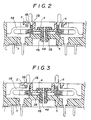
- the anchoring member is disposed on the socket body 1 in such a manner as to be able to move in the vertical direction (upward and downward) by the leg portion 4a, or otherwise, fixedly implanted therein without being resiliently held by the spring, as shown in Figs. 2 through 4, so that the anchoring member is incapable of movement in the vertical direction.
- a plurality of positioning holes 6 are arranged in parallel relation in marginal portions of four sides or two sides of the outer peripheral portion of the first supporting platform 2 at contact pitches, and therefore, at the equal pitches to those of the IC leads 7a.
- the holes 6 are adapted to receive contact portions 3b at distal ends of the corresponding contacts 3 in order to correctly position the contacts 3.
- the contacts 3 are implanted in the socket body portion at the outer peripheral portion of the first supporting platform 2.
- Each of the contacts 3 has an elastic contact element 3a extending toward the first supporting platform 2 from the implanted portion, and the contact portion 3b of the elastic contact element 3a is inserted into the corresponding positioning hole 6 as mentioned.
- the elastic contact element 3a is restricted the sideward displacement of the contact portion 3b in the positioning hole 6, to thereby establishing a relative position between the first supporting platform 2 and the contact 3.
- the elastic contact element 3a of the contact 3 is also displaced following thereto in order to maintain its relative position to the first supporting platform 2.
- the first supporting platform 2 can be moved forwardly and backwardly, rightwardly and leftwardly, and upwardly and downwardly, and is engaged with the second supporting platform 4 to restrict its raised position.
- the second supporting platform 4 is resiliently supported upwardly on the socket body 1 through a spring 8 interposed therebetween.
- the second supporting platform 4 is lowered against the spring 8 and raised in accordance with the spring 8. It isheld in its uppermost position against the spring 8.
- the embodiment shown in Figs. 2 through 4 includes a second supporting platform 4, which also acts as a retaining means, as in the embodiment shown in Figs. 5 through 7. Otherwise, it may include a retaining portion 4′ merely forming an anchoring member and expanding like the shape of a flange at an upper end of the leg portion 4a. The flange-like upper end of the retaining portion 4′ is retained at an upper peripheral edge of the central opening 2a to anchor the first supporting platform 2.
- the second supporting platform 4 (retaining portion 4′) is not resiliently held by a spring and the leg portion 4a is fixedly implanted in the socket body 1 so that it is incapable of moving upward and downward as mentioned above.
- the first supporting platform 2 When a flat type IC 7 is placed on the first supporting platform 2, the first supporting platform 2 is moved at the loosely engaged portion between the central opening 2a and the leg portion 4a in association with the movement of the flat type IC 7, and the elastic element 3a of each contact is also displaced following the movement thereof. As a result, relative positions between the IC leads 7a and the contact portions 3b of the contacts are maintained. At that time, the first supporting platform 2 is operated to correctly position the side edge of the IC body 7b through its IC positioning portion 2b, and support the IC lead 7a on an upper surface of the positioning portion. At the same time, the IC body 7b is supported by the second supporting platform 4 so that the former is brought into contact with the contact portion 3b of the contact 3.
- the IC may be designed such that the IC is originally not placed on the supporting platform but held in a state floating over the supporting platform. In that state, the IC lead 7a is placed on the contact portion 3b of the contact 3. When pushed down, the IC is supported on the first supporting platform, and the IC body is likewise supported on the second supporting platform 2.
- the relative position between the IC and supporting platform and the relative positions between the IC leads and contacts can be correctly corresponded with each other by smoothly and reliably moving the supporting platform in the horizontal direction at the loosely engaging portion between the supporting platform and the anchoring member. As a result, a highly reliable contact relation can be obtained.
- a stable contact relation can be obtained by supporting the IC both by the supporting platform for supporting the IC leads and by another supporting platform for supporting the IC body. Also, deformation of IC leads can effectively be prevented when they are brought into contact.
Landscapes
- Engineering & Computer Science (AREA)
- Microelectronics & Electronic Packaging (AREA)
- Connecting Device With Holders (AREA)
- Details Of Connecting Devices For Male And Female Coupling (AREA)
Applications Claiming Priority (2)
| Application Number | Priority Date | Filing Date | Title |
|---|---|---|---|
| JP274422/90 | 1990-10-12 | ||
| JP2274422A JPH0668983B2 (ja) | 1990-10-12 | 1990-10-12 | Icソケット |
Publications (2)
| Publication Number | Publication Date |
|---|---|
| EP0480668A1 true EP0480668A1 (fr) | 1992-04-15 |
| EP0480668B1 EP0480668B1 (fr) | 1995-01-11 |
Family
ID=17541455
Family Applications (1)
| Application Number | Title | Priority Date | Filing Date |
|---|---|---|---|
| EP91309198A Expired - Lifetime EP0480668B1 (fr) | 1990-10-12 | 1991-10-08 | Socle pour circuit intégré |
Country Status (7)
| Country | Link |
|---|---|
| US (1) | US5154619A (fr) |
| EP (1) | EP0480668B1 (fr) |
| JP (1) | JPH0668983B2 (fr) |
| KR (1) | KR920008997A (fr) |
| CA (1) | CA2053464A1 (fr) |
| DE (1) | DE69106652D1 (fr) |
| SG (1) | SG30495G (fr) |
Cited By (1)
| Publication number | Priority date | Publication date | Assignee | Title |
|---|---|---|---|---|
| GB2257849B (en) * | 1991-06-28 | 1995-11-22 | Digital Equipment Int | Semiconductor chip test jig |
Families Citing this family (12)
| Publication number | Priority date | Publication date | Assignee | Title |
|---|---|---|---|---|
| US5336096A (en) * | 1991-03-22 | 1994-08-09 | Enplas Corporation | IC socket and its contact pin |
| JP2551179Y2 (ja) * | 1991-06-27 | 1997-10-22 | 山一電機株式会社 | Icソケット |
| JPH06119959A (ja) * | 1992-10-05 | 1994-04-28 | Texas Instr Japan Ltd | ソケット |
| US5358421A (en) * | 1993-08-06 | 1994-10-25 | Minnesota Mining And Manufacturing Company | Zero-insertion-force socket for gull wing electronic devices |
| KR0123780Y1 (ko) * | 1994-11-01 | 1998-10-01 | 문정환 | 반도체디바이스용 소켓 |
| JP2980235B2 (ja) * | 1997-04-17 | 1999-11-22 | 山一電機株式会社 | Icパッケージ用icソケット |
| JP2004216082A (ja) * | 2003-01-10 | 2004-08-05 | Uni Charm Corp | パンツ型の使い捨て着用物品 |
| TWM351527U (en) * | 2008-06-16 | 2009-02-21 | Hon Hai Prec Ind Co Ltd | Electrical connector |
| US20100009825A1 (en) * | 2008-07-10 | 2010-01-14 | Ati Industrial Automation, Inc. | Compliant Service Transfer Module for Robotic Tool Changer |
| KR20120006301A (ko) * | 2010-07-12 | 2012-01-18 | 삼성전자주식회사 | 테스트 소켓 |
| JP6400342B2 (ja) * | 2014-06-11 | 2018-10-03 | 株式会社エンプラス | 電気部品用ソケット |
| JP7058194B2 (ja) * | 2018-07-27 | 2022-04-21 | 株式会社エンプラス | ソケット |
Citations (1)
| Publication number | Priority date | Publication date | Assignee | Title |
|---|---|---|---|---|
| US4887969A (en) * | 1987-05-22 | 1989-12-19 | Yamaichi Electric Mfg. Co., Ltd. | IC socket |
Family Cites Families (6)
| Publication number | Priority date | Publication date | Assignee | Title |
|---|---|---|---|---|
| US4541676A (en) * | 1984-03-19 | 1985-09-17 | Itt Corporation | Chip carrier test adapter |
| JPS62160676A (ja) * | 1985-12-31 | 1987-07-16 | 日本テキサス・インスツルメンツ株式会社 | ソケツト |
| US4750890A (en) * | 1987-06-18 | 1988-06-14 | The J. M. Ney Company | Test socket for an integrated circuit package |
| JPH01119043A (ja) * | 1987-10-31 | 1989-05-11 | Yamaichi Electric Mfg Co Ltd | Icソケット |
| JPH0636388B2 (ja) * | 1988-03-08 | 1994-05-11 | 山一電機工業株式会社 | Icキャリア搭載形ソケットにおける位置決め方法 |
| US4824389A (en) * | 1988-04-26 | 1989-04-25 | Precision Connector Designs, Inc. | Socket for electronic component |
-
1990
- 1990-10-12 JP JP2274422A patent/JPH0668983B2/ja not_active Expired - Fee Related
-
1991
- 1991-10-08 EP EP91309198A patent/EP0480668B1/fr not_active Expired - Lifetime
- 1991-10-08 CA CA002053464A patent/CA2053464A1/fr not_active Abandoned
- 1991-10-08 US US07/773,115 patent/US5154619A/en not_active Expired - Lifetime
- 1991-10-08 DE DE69106652T patent/DE69106652D1/de not_active Expired - Lifetime
- 1991-10-10 KR KR1019910017734A patent/KR920008997A/ko not_active Withdrawn
-
1995
- 1995-02-21 SG SG30495A patent/SG30495G/en unknown
Patent Citations (1)
| Publication number | Priority date | Publication date | Assignee | Title |
|---|---|---|---|---|
| US4887969A (en) * | 1987-05-22 | 1989-12-19 | Yamaichi Electric Mfg. Co., Ltd. | IC socket |
Cited By (1)
| Publication number | Priority date | Publication date | Assignee | Title |
|---|---|---|---|---|
| GB2257849B (en) * | 1991-06-28 | 1995-11-22 | Digital Equipment Int | Semiconductor chip test jig |
Also Published As
| Publication number | Publication date |
|---|---|
| SG30495G (en) | 1995-08-18 |
| US5154619A (en) | 1992-10-13 |
| JPH0668983B2 (ja) | 1994-08-31 |
| CA2053464A1 (fr) | 1992-04-13 |
| JPH04149980A (ja) | 1992-05-22 |
| KR920008997A (ko) | 1992-05-28 |
| EP0480668B1 (fr) | 1995-01-11 |
| DE69106652D1 (de) | 1995-02-23 |
Similar Documents
| Publication | Publication Date | Title |
|---|---|---|
| US5154619A (en) | Ic socket | |
| US4887969A (en) | IC socket | |
| US5375710A (en) | IC carrier | |
| EP0228279B1 (fr) | Socle pour l'enfichage d'un composant à circuit intégré | |
| US5100332A (en) | IC socket | |
| US6666691B2 (en) | Socket for removably mounting electronic packages | |
| EP0503810B1 (fr) | Connecteur de circuit integré sans fil | |
| US5009609A (en) | Contact shutter device in IC socket | |
| EP0666706A2 (fr) | Fiche d'adaptation pour le test de déverminage | |
| US5045923A (en) | Contact structure in socket with IC carrier placed thereon | |
| GB2188797A (en) | Chip connector | |
| EP0481726B1 (fr) | Douille pour une pièce électrique | |
| US5114358A (en) | Chip carrier socket | |
| US6679715B2 (en) | Socket for electrical parts | |
| US5205756A (en) | Chip carrier socket | |
| US4997378A (en) | Contact | |
| JP2895039B1 (ja) | Icソケット | |
| US5277594A (en) | Connector | |
| JP2656901B2 (ja) | Icソケット | |
| JPH06140115A (ja) | Icソケット | |
| JP2669409B2 (ja) | Zip用icソケット | |
| JPH0747829Y2 (ja) | Zif式icソケット | |
| JPH0817534A (ja) | Icソケット | |
| JPH07114137B2 (ja) | Icソケット | |
| JPH06140114A (ja) | Icソケット |
Legal Events
| Date | Code | Title | Description |
|---|---|---|---|
| PUAI | Public reference made under article 153(3) epc to a published international application that has entered the european phase |
Free format text: ORIGINAL CODE: 0009012 |
|
| AK | Designated contracting states |
Kind code of ref document: A1 Designated state(s): DE FR GB IT |
|
| 17P | Request for examination filed |
Effective date: 19920514 |
|
| 17Q | First examination report despatched |
Effective date: 19931020 |
|
| RAP1 | Party data changed (applicant data changed or rights of an application transferred) |
Owner name: YAMAICHI ELECTRONICS CO., LTD. |
|
| GRAA | (expected) grant |
Free format text: ORIGINAL CODE: 0009210 |
|
| AK | Designated contracting states |
Kind code of ref document: B1 Designated state(s): DE FR GB IT |
|
| PG25 | Lapsed in a contracting state [announced via postgrant information from national office to epo] |
Ref country code: IT Free format text: LAPSE BECAUSE OF FAILURE TO SUBMIT A TRANSLATION OF THE DESCRIPTION OR TO PAY THE FEE WITHIN THE PRE;WARNING: LAPSES OF ITALIAN PATENTS WITH EFFECTIVE DATE BEFORE 2007 MAY HAVE OCCURRED AT ANY TIME BEFORE 2007. THE CORRECT EFFECTIVE DATE MAY BE DIFFERENT FROM THE ONE RECORDED.SCRIBED TIME-LIMIT Effective date: 19950111 Ref country code: FR Effective date: 19950111 |
|
| REF | Corresponds to: |
Ref document number: 69106652 Country of ref document: DE Date of ref document: 19950223 |
|
| PG25 | Lapsed in a contracting state [announced via postgrant information from national office to epo] |
Ref country code: DE Effective date: 19950412 |
|
| EN | Fr: translation not filed | ||
| PLBE | No opposition filed within time limit |
Free format text: ORIGINAL CODE: 0009261 |
|
| STAA | Information on the status of an ep patent application or granted ep patent |
Free format text: STATUS: NO OPPOSITION FILED WITHIN TIME LIMIT |
|
| 26N | No opposition filed | ||
| PGFP | Annual fee paid to national office [announced via postgrant information from national office to epo] |
Ref country code: GB Payment date: 19961002 Year of fee payment: 6 |
|
| PG25 | Lapsed in a contracting state [announced via postgrant information from national office to epo] |
Ref country code: GB Free format text: LAPSE BECAUSE OF NON-PAYMENT OF DUE FEES Effective date: 19971008 |
|
| GBPC | Gb: european patent ceased through non-payment of renewal fee |
Effective date: 19971008 |