EP0480672B1 - Dispositif et procédé de fabrication de pneus crus - Google Patents
Dispositif et procédé de fabrication de pneus crus Download PDFInfo
- Publication number
- EP0480672B1 EP0480672B1 EP91309206A EP91309206A EP0480672B1 EP 0480672 B1 EP0480672 B1 EP 0480672B1 EP 91309206 A EP91309206 A EP 91309206A EP 91309206 A EP91309206 A EP 91309206A EP 0480672 B1 EP0480672 B1 EP 0480672B1
- Authority
- EP
- European Patent Office
- Prior art keywords
- conveyor
- tyre
- downstream
- sector
- cut
- Prior art date
- Legal status (The legal status is an assumption and is not a legal conclusion. Google has not performed a legal analysis and makes no representation as to the accuracy of the status listed.)
- Expired - Lifetime
Links
- 238000004519 manufacturing process Methods 0.000 title claims description 16
- 238000000034 method Methods 0.000 title description 9
- 238000011144 upstream manufacturing Methods 0.000 claims description 31
- 238000012546 transfer Methods 0.000 claims description 29
- 238000005520 cutting process Methods 0.000 claims description 20
- 239000004744 fabric Substances 0.000 claims description 17
- 230000001154 acute effect Effects 0.000 claims description 5
- 238000004804 winding Methods 0.000 claims description 4
- 239000000463 material Substances 0.000 description 11
- 229910000831 Steel Inorganic materials 0.000 description 9
- 239000010959 steel Substances 0.000 description 9
- 230000009471 action Effects 0.000 description 7
- 230000008569 process Effects 0.000 description 6
- 238000005259 measurement Methods 0.000 description 4
- 239000003638 chemical reducing agent Substances 0.000 description 3
- 230000003014 reinforcing effect Effects 0.000 description 3
- 239000011324 bead Substances 0.000 description 2
- 230000008878 coupling Effects 0.000 description 2
- 238000010168 coupling process Methods 0.000 description 2
- 238000005859 coupling reaction Methods 0.000 description 2
- 230000006872 improvement Effects 0.000 description 2
- 238000000926 separation method Methods 0.000 description 2
- 241000254043 Melolonthinae Species 0.000 description 1
- 238000013459 approach Methods 0.000 description 1
- 230000008859 change Effects 0.000 description 1
- 238000001514 detection method Methods 0.000 description 1
- 238000006073 displacement reaction Methods 0.000 description 1
- 230000009189 diving Effects 0.000 description 1
- 230000001788 irregular Effects 0.000 description 1
- 230000014759 maintenance of location Effects 0.000 description 1
- 230000007246 mechanism Effects 0.000 description 1
- 230000004048 modification Effects 0.000 description 1
- 238000012986 modification Methods 0.000 description 1
- 238000002360 preparation method Methods 0.000 description 1
- 230000002787 reinforcement Effects 0.000 description 1
- 230000004044 response Effects 0.000 description 1
- 238000007493 shaping process Methods 0.000 description 1
- 230000001360 synchronised effect Effects 0.000 description 1
Images




Classifications
-
- B—PERFORMING OPERATIONS; TRANSPORTING
- B29—WORKING OF PLASTICS; WORKING OF SUBSTANCES IN A PLASTIC STATE IN GENERAL
- B29D—PRODUCING PARTICULAR ARTICLES FROM PLASTICS OR FROM SUBSTANCES IN A PLASTIC STATE
- B29D30/00—Producing pneumatic or solid tyres or parts thereof
- B29D30/06—Pneumatic tyres or parts thereof (e.g. produced by casting, moulding, compression moulding, injection moulding, centrifugal casting)
- B29D30/08—Building tyres
- B29D30/20—Building tyres by the flat-tyre method, i.e. building on cylindrical drums
- B29D30/30—Applying the layers; Guiding or stretching the layers during application
- B29D30/3007—Applying the layers; Guiding or stretching the layers during application by feeding a sheet perpendicular to the drum axis and joining the ends to form an annular element
-
- B—PERFORMING OPERATIONS; TRANSPORTING
- B29—WORKING OF PLASTICS; WORKING OF SUBSTANCES IN A PLASTIC STATE IN GENERAL
- B29D—PRODUCING PARTICULAR ARTICLES FROM PLASTICS OR FROM SUBSTANCES IN A PLASTIC STATE
- B29D30/00—Producing pneumatic or solid tyres or parts thereof
- B29D30/06—Pneumatic tyres or parts thereof (e.g. produced by casting, moulding, compression moulding, injection moulding, centrifugal casting)
- B29D30/38—Textile inserts, e.g. cord or canvas layers, for tyres; Treatment of inserts prior to building the tyre
- B29D30/44—Stretching or treating the layers before application on the drum
- B29D2030/4406—Adjusting the positions of the layers
-
- B—PERFORMING OPERATIONS; TRANSPORTING
- B29—WORKING OF PLASTICS; WORKING OF SUBSTANCES IN A PLASTIC STATE IN GENERAL
- B29D—PRODUCING PARTICULAR ARTICLES FROM PLASTICS OR FROM SUBSTANCES IN A PLASTIC STATE
- B29D30/00—Producing pneumatic or solid tyres or parts thereof
- B29D30/06—Pneumatic tyres or parts thereof (e.g. produced by casting, moulding, compression moulding, injection moulding, centrifugal casting)
- B29D30/38—Textile inserts, e.g. cord or canvas layers, for tyres; Treatment of inserts prior to building the tyre
- B29D30/44—Stretching or treating the layers before application on the drum
- B29D2030/4406—Adjusting the positions of the layers
- B29D2030/4418—Adjusting the positions of the layers laterally, e.g. sideways
-
- B—PERFORMING OPERATIONS; TRANSPORTING
- B29—WORKING OF PLASTICS; WORKING OF SUBSTANCES IN A PLASTIC STATE IN GENERAL
- B29L—INDEXING SCHEME ASSOCIATED WITH SUBCLASS B29C, RELATING TO PARTICULAR ARTICLES
- B29L2030/00—Pneumatic or solid tyres or parts thereof
- B29L2030/003—Plies; Breakers
Definitions
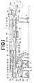
- This invention relates to an apparatus and method of manufacture for a green tyre and in particular for supplying a tyre component, for example, a reinforced fabric material usually of steel cord, such as is used for a tyre carcass or a steel breaker which is fed as a predetermined cut length to a green tyre building drum.
- a tyre component for example, a reinforced fabric material usually of steel cord, such as is used for a tyre carcass or a steel breaker which is fed as a predetermined cut length to a green tyre building drum.
- This operation involves cutting, separating the cut component from the following continuous portions and guiding the cut component with positioning thereof.
- green tyres are manufacture by several steps.
- a first step is to build or assembly a cylindrical tyre carcass by fitting a pair of beads one over either end of the cylindrical carcass, folding back the two ends of the cylinder around the beads and attaching two sidewalls for form a green carcass.
- a belt reinforcement is formed and then fitted around the green carcass which is shaped up into a toroid and bonding the belt to the green carcass. Finally tread is fitted.
- tyre components or tyre materials for example, tow plies of steel breaker, a reinforcing band and a rubber tread strip are supplied in turn in a direction perpendicular to the axis of a belt building drum to a belt assembly stage, the components being in order of winding and fitting to the drum to form an annual belt/tread assembly.
- the three stage guide pan conveyor for supplying the breakers to the drum has each level independently driven and includes frames for supporting the guide pans so they may be moved towards and away from the drum by pivoting in a vertical direction.
- Another aspect of the invention provides a manufacturing apparatus characterised in that of the upstream and downstream conveyor sections of the separating means the rollers of one sector are driven for rotation and rollers of the other sector are of free rotation.
- a plurality of the components can be supplied using only one guide pan, and therefore, connection/disconnection of the guide pan apparatus to the vertically pluralised transfer apparatus and a move to the standby position thereof are permitted so that the apparatus is fully effective but is simple in structure, requires less space than hitherto and is easy to adjust. It is more compact and cheaper to maintain.
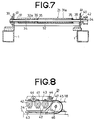
- the separating apparatus 21 comprises an upstream conveying sector 32 and a downstream conveying sector 31. All the rollers are arranged laterally side by side, but most rollers have two portions, an upstream portions 32a and a downstream portion 31a, to provide a slant cut line 33. Specifically, there are provided many rollers having various long to short lengths which are arranged on two laterally opposite sides of the slant line 33 which is angled to the direction of transferring the breakers.
- a toothed pulley 49 is mounted, over which a drive belt 50 for driving the first conveyor 18 is placed.
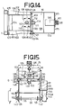
- the mounting frame 15 comprises two opposite side plates 102,102, front end plate 103, an interconnecting member 104 which connects two rear ends of the side plates 102, rear end plate 105 secured to the rear ends of the two side plates 102, and a reinforcing member 105, wherein the rear end plate 105 is secured to the front end of the main frame structure 1.
- a servo motor 108 On the two ends of the front face of the front plate 103 set are guide rails 107, and on the upper face of the frame is mounted a servo motor 108, on a mounting plate 10a, for driving the vertically mobile frame with its output shaft 110 held upwardly and at a central upper portion of the front end plate 103, a screw shaft 111 for vertical drive is set vertical rotatably in a bearing 112.
- toothed pulleys 113,114 are mounted, and a drive belt 115 is placed over these two pulleys 113,114.
- bolts 116 for suspending the belt conveyor 20 are set to be vertically adjustable by nuts 117.
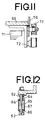
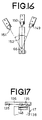
- a stopper 118 At the low end of the guide rail 107 set is a stopper 118, and at the right side end of the front end plate 103, a proximity switch 119 for detecting a stop point for the vertical movement is set to be positionally adjustable (the same arrangement as in Figure 17).
- the vertically mobile frame 16 is generally a box having a bottom, and on the rear face of a rear end plate 120 of the vertically mobile frame 16, guide shoes 121 for engaging the guide rails 107 as mentioned above are provided at right, left and upper, lower positions.
- a ball nut 122 is mounted, to which nut 122 the screw shaft 111 as mentioned above is engaged to be freely rotatable.
- a kicker 124 for the proximity switch 119 (see Figure 17).
- a bearing 131 At a centrally front position of the same back side of the bottom plate 129 set is a bearing 131, by which bearing 131 a screw shaft 132 for driving the front/rear movement is rotatably mounted.
- the first conveyors 18 of the upper and lower transferring apparatus 6,7 are put into drive, and the front end of the breakers 12,13 are led to predetermined positions in the cutter devices 26 for cutting the predetermined length, wherein guide actions of the side guide rollers 24 of the positioning means 25, and the omni rollers 23 rotatable front/rear and right/left are involved. then, the upper and lower first conveyors 18 are stopped and the square front end portion of the breaker is cut slantly by the cutter device 26 to form a triangular front edge. Thus, the upper and lower lines both have finished the job of shaping the breaker web.
- the first and second conveyors 18,19 of the upper line 6 are put into drive and the measurement of a length by the rotary encoder resumes, and when the cut line 33 of the breaker 12 comes to the central point of the separating apparatus 21, the first conveyor 18 and the separating rollers 32a which are drive-connected to the first conveyor 18 re stopped and only the second conveyor 19 is driven.
- the cut breaker 12a is separated at the cut edge from subsequent breaker material and is transferred further and is then put into a standby status on the second conveyor 19.
- the sub-guide 65 moves forward to contact the side portions of the breaker 12a for assisting an adequate positioning on the drum 2.
- the guides 62,63 of the guide pan apparatus 14 are retreated and put into a standby position to wait for the next cut breaker 13a.
- the triangular front edge comes to be the left side as shown in Figures 3 and 6, the sub-guide at left side 84 is put into action.
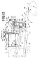
- the servo motor 145 starts the pivotal shaft 66 to pivot in a direction as shown by Y in Figure 13 so that the front end of the guide pan apparatus 14 moves upward and comes away from the drum 2, and then stops at a predetermined position.
- the vertically mobile frame 16 raises and stops at the upper limit point, and the front/rear mobile frame 17 moves forwards and stops at the forward limit point, and the guide pan apparatus 14 is moved to the standby position as shown in two dot lines in Figure 1.
- Control of all operations to be performed by each apparatus or device is by a program control system based on computers.
- the fabric may be cut from steel cord chafer; the transfer apparatus may include three or four levels; the transhipping conveyor 20 may be replaced with the extended second conveyor 19, further sub-guides 64,65 may be adapted to be synchronised and to move simultaneously with the right and left sides.
- the guide pan apparatus 14 is only provided with vertical and/or pivotal mobility, it is permitted to extend two brackets from the vertical mobile frame 16 and provide a shaft which extends through the two brackets, and thus, the guide pan apparatus 14 may be made movable about this shaft.
Landscapes
- Engineering & Computer Science (AREA)
- Mechanical Engineering (AREA)
- Tyre Moulding (AREA)
Claims (9)
- Appareil de confection de pneumatique non vulcanisé, comprenant un dispositif (8, 9) de déroulement d'une étoffe en forme de feuille d'un rouleau (10, 11), un dispositif (6, 7) de transfert de l'élément déroulé en direction longitudinale, un dispositif à organe de coupe (26) destiné à couper un élément de pneumatique (12, 13) suivant un angle prédéterminé présentant une inclinaison par rapport à la direction de transfert, et un dispositif à cuvette (14) de guidage en aval de la partie coupée (12) de l'élément de pneumatique en assurant un positionnement suivant la largeur, l'appareil comprenant un dispositif de transmission de l'élément coupé à une longueur prédéterminée afin qu'il soit enroulé sur un tambour de confection d'un pneumatique non vulcanisé, caractérisé en ce que le dispositif de transfert (6, 7) comprend un premier transporteur (18) disposé en amont du dispositif de transfert et un second transporteur (19) disposé en aval de ce dispositif de transfert, le premier et le second transporteur (18, 19) étant entraînés indépendamment, un dispositif de séparation (21) placé entre le premier et le second transporteur (18, 19) et destiné à séparer une partie de l'élément (12) de pneumatique, coupé par le dispositif à organe de coupe (26) afin qu'il ait une longueur prédéterminée et soit disposé en aval, des parties suivantes de l'étoffe du pneumatique placée en amont, dans lequel le dispositif de séparation (21) comprend un secteur de transporteur amont (32) et un secteur de transporteur aval (31), le transporteur (32) du secteur amont et le transporteur (31) du secteur aval étant séparés par une ligne intermédiaire inclinée par rapport à la direction de transfert, la ligne intermédiaire étant pratiquement parallèle à la ligne de coupe par le dispositif (26) à organe de coupe, et les transporteurs des secteurs amont et aval (32, 31) du dispositif de séparation (21) comprennent de nombreux rouleaux ayant des longueurs différentes, montés afin qu'ils tournent et disposés suivant la largeur de côtés opposés de la ligne inclinée, et un rouleau du secteur amont (32) et un rouleau du secteur aval (31) de transporteur ont un arbre central commun (34), et chaque paire de rouleaux des secteurs amont et aval comporte des manchons (32a, 31a) montés sur l'arbre central commun (34), les manchons (32a, 31a) des rouleaux du secteur amont (32) étant fixés aux arbres communs (34) et les manchons (31a) du secteur aval (31) de transporteur étant montés librement sur les arbres centraux communs (34), les arbres centraux communs (34) sont raccordés au premier transporteur (18) du dispositif de transfert (6, 7) afin qu'ils soient entraînés, et les manchons (32a) des rouleaux du secteur amont (32) et les manchons (31a) du secteur aval (31) de transporteur ont des longueurs différentes sur les arbres centraux communs, si bien que les différences de longueur entre les manchons amont (32a) et les manchons aval (31a) changent progressivement dans la direction de transfert.
- Appareil de confection de pneumatique non vulcanisé selon la revendication 1, caractérisé en ce que, dans les secteurs amont et aval (32, 31) de transporteur du dispositif de séparation, des rouleaux d'un premier secteur sont entraînés afin qu'ils tournent et ceux de l'autre secteur tournent librement.
- Appareil de confection de pneumatique non vulcanisé selon la revendication 1, caractérisé en ce que les rouleaux des secteurs amont et aval (32, 31) de transporteur du dispositif de séparation (21) peuvent tourner librement.
- Appareil de confection de pneumatique non vulcanisé selon la revendication 2, caractérisé en ce que les rouleaux du secteur amont (32) du dispositif de séparation (21) sont entraînés en synchronisme avec le premier transporteur (18) et les rouleaux du secteur aval (31) peuvent tourner librement.
- Appareil de confection de pneumatique non vulcanisé selon l'une quelconque des revendications 1 à 4, caractérisé en ce que le dispositif (14) à cuvette de guidage comprend un transporteur (60) de transfert d'éléments de pneumatique, le transporteur (60) ayant des organes de guidage (62, 63) placés sur les côtés opposés du transporteur, les deux organes opposés de guidage (62, 63) étant destinés à être mobiles ensemble afin qu'ils se rapprochent et s'écartent et guident les deux côtés de l'élément d'étoffe de pneumatique qui est transféré.
- Appareil de confection de pneumatique non vulcanisé selon la revendication 5, caractérisé en ce que, dans le dispositif (14) à culot de guidage, des rouleaux entraînés ensemble sont destinés à délimiter une surface de transport de travail sur laquelle est transféré l'élément de pneumatique.
- Appareil de confection de pneumatique non vulcanisé selon la revendication 5, caractérisé en ce que des organes auxiliaires de guidage (64, 65) sont placés en avant des organes de guidage (62, 63), et les organes auxiliaires de guidage (64, 65) sont destinés à être mobiles latéralement afin que ces organes auxiliaires (64, 65) puissent reculer l'un par rapport à l'autre lors du passage d'une partie avant aiguë de l'élément de pneumatique afin que le contact des côtés soit évité, si bien que les organes auxiliaires de guidage (64, 65) sont ajustés en position l'un par rapport à l'autre afin qu'ils quittent l'élément de pneumatique par contact des côtés après le passage de la partie aiguë.
- Appareil de confection de pneumatique non vulcanisé selon l'une quelconque des revendications 1 à 7, caractérisé en ce que le dispositif de déroulement comprend plusieurs appareils de déroulement (8, 9), le dispositif de transfert (6, 7) est espacé verticalement afin qu'il donne plusieurs niveaux de traitement en nombre égal au nombre d'appareils de déroulement (8, 9), le dispositif à cuvette de guidage (14) est destiné au moins à être mobile verticalement et/ou à pivoter verticalement, le dispositif à cuvette de guidage (14) a une extrémité arrière destinée à raccorder ou déconnecter une extrémité avant d'un second transporteur placé à chaque niveau du dispositif de transfert à structure verticale, et le dispositif à cuvette verticale (14) a une extrémité avant qui peut être adjacente au tambour de confection (2) de pneumatique non vulcanisé.
- Procédé de fabrication d'un pneumatique non vulcanisé, qui comprend la transmission d'un élément de pneumatique armé d'étoffe sous forme d'une feuille déroulée d'un rouleau vers un dispositif de transfert (6, 7), la découpe, sur le dispositif de transfert (6, 7), de l'élément de pneumatique en un point qui se trouve à une longueur prédéterminée en arrière de son bord avant, avec une découpe inclinée d'un angle par rapport à la direction de transfert, la transmission de l'élément coupé (12, 13) d'un dispositif à cuvette de guidage (14) ayant un dispositif de positionnement et de guidage des bords, puis la transmission de l'élément de pneumatique vers un tambour de confection d'un pneumatique non vulcanisé pour son assemblage, caractérisé par la séparation de l'élément de pneumatique coupé de l'étoffe suivante par transfert de l'élément coupé (12, 13) et de l'étoffe suivante vers un dispositif de séparation (21), l'arrêt du transfert de l'élément coupé (12, 13) et de l'étoffe suivante lorsqu'une ligne inclinée de découpe entre eux vient au point central du dispositif de séparation (21) si bien que l'élément coupé (12, 13) et l'étoffe qui suit sont positionnés respectivement sur des secteurs aval et amont (31, 32) de transporteur du dispositif de séparation (21), et la ligne inclinée de coupe est adjacente et pratiquement alignée sur une ligne intermédiaire inclinée d'un angle par rapport à la direction de transfert séparant les secteurs aval et amont (31, 32) de transporteur, puis la reprise du transfert de l'élément coupé (12, 13) sur le secteur aval (31) afin que l'élément coupé (12, 13) se déplace par rapport à l'étoffe suivante d'élément et se sépare de celle-ci.
Applications Claiming Priority (6)
| Application Number | Priority Date | Filing Date | Title |
|---|---|---|---|
| JP274009/90 | 1990-10-11 | ||
| JP27400990 | 1990-10-11 | ||
| JP274008/90 | 1990-10-11 | ||
| JP2274008A JPH04147835A (ja) | 1990-10-11 | 1990-10-11 | タイヤ構成材料供給ガイドパン装置 |
| JP338911/90 | 1990-11-30 | ||
| JP2338911A JPH04214333A (ja) | 1990-10-11 | 1990-11-30 | タイヤ構成材料供給貼付方法及びその装置 |
Publications (3)
| Publication Number | Publication Date |
|---|---|
| EP0480672A2 EP0480672A2 (fr) | 1992-04-15 |
| EP0480672A3 EP0480672A3 (en) | 1992-09-02 |
| EP0480672B1 true EP0480672B1 (fr) | 1995-06-14 |
Family
ID=27336148
Family Applications (1)
| Application Number | Title | Priority Date | Filing Date |
|---|---|---|---|
| EP91309206A Expired - Lifetime EP0480672B1 (fr) | 1990-10-11 | 1991-10-08 | Dispositif et procédé de fabrication de pneus crus |
Country Status (3)
| Country | Link |
|---|---|
| US (1) | US5271790A (fr) |
| EP (1) | EP0480672B1 (fr) |
| DE (1) | DE69110396T2 (fr) |
Cited By (1)
| Publication number | Priority date | Publication date | Assignee | Title |
|---|---|---|---|---|
| DE102014225142A1 (de) | 2014-12-08 | 2016-06-09 | Continental Reifen Deutschland Gmbh | Reifenaufbauanlage |
Families Citing this family (14)
| Publication number | Priority date | Publication date | Assignee | Title |
|---|---|---|---|---|
| NL9301717A (nl) * | 1993-10-06 | 1995-05-01 | Vmi Epe Holland | Werkwijze voor het aanpassen van een zijde van een strook flexibel materiaal aan een referentiezijde en gordelstrooktoevoerinrichting voor het toevoeren van een gordelstrook op een ronddraaiende opbouwtrommel. |
| US5524804A (en) * | 1995-02-14 | 1996-06-11 | Bridgestone/Firestone, Inc. | Lock-out device for threading in a strip guide apparatus |
| US6215205B1 (en) * | 1996-08-06 | 2001-04-10 | The Goodyear Tire & Rubber Company | Adjustable length conveyor system |
| NL1015250C2 (nl) * | 2000-05-19 | 2001-11-22 | Vmi Epe Holland | Lasinrichting voor het aan elkaar lassen van stroken van in rubbermateriaal ingebedde koorden. |
| NL1016078C2 (nl) * | 2000-09-01 | 2002-03-05 | Vmi Epe Holland | Lasinrichting voor het aan elkaar lassen van stroken van in rubbermateriaal ingebedde koorden. |
| WO2006106562A1 (fr) * | 2005-03-29 | 2006-10-12 | Toyo Tire & Rubber Co., Ltd. | Procede et appareil de fabrication d'une ceinture de pneumatique |
| CN101304870A (zh) * | 2005-11-10 | 2008-11-12 | 米其林技术公司 | 制造轮胎的装置和转换装配线以制造不同类型轮胎的方法 |
| WO2012139556A1 (fr) * | 2011-04-12 | 2012-10-18 | Harburg-Freudenberg Maschinenbau Gmbh | Procédé et dispositif permettant d'orienter une bande de protection |
| ITMI20112269A1 (it) * | 2011-12-15 | 2013-06-16 | Pirelli | Metodo per controllare la deposizione di uno strato di materiale polimerico sigillante su un tamburo di formatura e processo per produrre pneumatici auto-sigillanti per ruote di veicoli |
| CN106743953B (zh) * | 2016-12-14 | 2018-10-30 | 重庆市九龙橡胶制品制造有限公司 | 反光轮胎的辅助生产设备 |
| NL2019785B1 (en) * | 2017-10-23 | 2019-04-29 | Vmi Holland Bv | Tire building apparatus and method for joining or cutting tire components |
| CN115139558B (zh) * | 2022-04-24 | 2024-11-01 | 杭州中策清泉实业有限公司 | 智能化尼龙包布复合装备及其复合方法 |
| SE545968C2 (en) * | 2022-07-08 | 2024-03-26 | Pulpac AB | Method for transporting a cellulose blank structure via a buffering module and buffering module |
| CN117303073A (zh) * | 2023-11-14 | 2023-12-29 | 软控股份有限公司 | 引料装置及帘布裁断系统 |
Family Cites Families (13)
| Publication number | Priority date | Publication date | Assignee | Title |
|---|---|---|---|---|
| US3130100A (en) * | 1956-07-17 | 1964-04-21 | Goodrich Co B F | Method and apparatus for butt splicing sheet material |
| US3444030A (en) * | 1963-10-21 | 1969-05-13 | Gen Tire & Rubber Co | Conveyer length adjustment mechanism |
| US3407106A (en) * | 1964-08-24 | 1968-10-22 | Bacon American Corp | Apparatus for retreading tires |
| US3413174A (en) * | 1965-03-15 | 1968-11-26 | Goodrich Co B F | Conveyor apparatus |
| JPS5133594B2 (fr) * | 1972-11-09 | 1976-09-20 | ||
| US4006816A (en) * | 1975-05-30 | 1977-02-08 | Alvey Inc. | Article antiscrambling and accumulating roller conveyor |
| JPS5324463A (en) * | 1976-08-11 | 1978-03-07 | Seiichi Tadami | Method of patterning matting materials |
| DE2639689A1 (de) * | 1976-09-03 | 1978-03-09 | Continental Gummi Werke Ag | Einrichtung zum zufuehren von ein- und auflagestreifen fuer luftreifen auf die wickeltrommel von reifen-aufbaumaschinen |
| DE2743502A1 (de) * | 1977-09-28 | 1979-04-05 | Phoenix Ag | Vorrichtung zum herstellen von guerteln fuer luftreifen |
| US4333788A (en) * | 1980-04-04 | 1982-06-08 | Cooper Tire & Rubber Company | Tire building machine servicer |
| JPS5859829A (ja) * | 1981-10-06 | 1983-04-09 | Kobe Steel Ltd | ゴムシ−ト材料の搬送成形装置 |
| JPS61148037A (ja) * | 1984-12-24 | 1986-07-05 | Yokohama Rubber Co Ltd:The | タイヤ成形機に於けるタイヤ構成材料の自動供給装置 |
| US4769104A (en) * | 1986-11-11 | 1988-09-06 | Bridgestone Corporation | Apparatus for sticking a tire component member |
-
1991
- 1991-10-08 EP EP91309206A patent/EP0480672B1/fr not_active Expired - Lifetime
- 1991-10-08 DE DE69110396T patent/DE69110396T2/de not_active Expired - Fee Related
- 1991-10-11 US US07/774,813 patent/US5271790A/en not_active Expired - Fee Related
Cited By (1)
| Publication number | Priority date | Publication date | Assignee | Title |
|---|---|---|---|---|
| DE102014225142A1 (de) | 2014-12-08 | 2016-06-09 | Continental Reifen Deutschland Gmbh | Reifenaufbauanlage |
Also Published As
| Publication number | Publication date |
|---|---|
| EP0480672A3 (en) | 1992-09-02 |
| DE69110396T2 (de) | 1995-11-02 |
| DE69110396D1 (de) | 1995-07-20 |
| EP0480672A2 (fr) | 1992-04-15 |
| US5271790A (en) | 1993-12-21 |
Similar Documents
| Publication | Publication Date | Title |
|---|---|---|
| US5271790A (en) | Apparatus and method of manufacture for a green tire | |
| CN111702032B (zh) | 一种放卷机构 | |
| US6192955B1 (en) | Apparatus and method for aligning webs | |
| US5882457A (en) | Tire tread guiding | |
| US20090126874A1 (en) | Supply device for a tire-building drum | |
| EP0384083B1 (fr) | Procédé et dispositif pour aligner un élément en forme de bande | |
| JPS6147701B2 (fr) | ||
| AU2009270215B2 (en) | Plastic film stretching apparatus | |
| EP0447273A2 (fr) | Procédé et appareil pour couper et enrouler sur un tambour une pièce en forme de courroie | |
| CN216970892U (zh) | 一种可对胎料输送自动纠偏的上鼓输送架 | |
| US4993334A (en) | Sewing station for pieces of material | |
| EP0109475B1 (fr) | Dispositif pour corriger la longueur de bandes élastomères dans la fabrication des pneus | |
| GB2090234A (en) | Guiding cut strips along roller centreline during tyre formation | |
| JPH0348024B2 (fr) | ||
| JPH04214333A (ja) | タイヤ構成材料供給貼付方法及びその装置 | |
| JP3007113B2 (ja) | 帯状ゴム部材の貼付け方法および装置 | |
| JP2824339B2 (ja) | タイヤ成形機の材料巻付装置 | |
| JP4167003B2 (ja) | 加硫済トレッド部材の切断方法 | |
| JPH06238772A (ja) | オートスプライス装置 | |
| KR920009953B1 (ko) | 타이어용 코드지의 재단방법과 그 장치 | |
| JP3090217B2 (ja) | 帯状部材を成型ドラムに供給する方法および装置 | |
| JP3273653B2 (ja) | 軟弱帯状部材のセンターリング装置 | |
| KR100460390B1 (ko) | 조인트 분산이 용이한 타이어 반제품 절단장치 | |
| CN120503453B (zh) | 带束鼓工位自动供料装置 | |
| EP0482830B1 (fr) | Procédé et dispositif pour la fabrication d'ébauches de pneus |
Legal Events
| Date | Code | Title | Description |
|---|---|---|---|
| PUAI | Public reference made under article 153(3) epc to a published international application that has entered the european phase |
Free format text: ORIGINAL CODE: 0009012 |
|
| AK | Designated contracting states |
Kind code of ref document: A2 Designated state(s): DE FR GB |
|
| PUAL | Search report despatched |
Free format text: ORIGINAL CODE: 0009013 |
|
| AK | Designated contracting states |
Kind code of ref document: A3 Designated state(s): DE FR GB |
|
| 17P | Request for examination filed |
Effective date: 19920915 |
|
| 17Q | First examination report despatched |
Effective date: 19940208 |
|
| GRAA | (expected) grant |
Free format text: ORIGINAL CODE: 0009210 |
|
| AK | Designated contracting states |
Kind code of ref document: B1 Designated state(s): DE FR GB |
|
| REF | Corresponds to: |
Ref document number: 69110396 Country of ref document: DE Date of ref document: 19950720 |
|
| ET | Fr: translation filed | ||
| PLBE | No opposition filed within time limit |
Free format text: ORIGINAL CODE: 0009261 |
|
| STAA | Information on the status of an ep patent application or granted ep patent |
Free format text: STATUS: NO OPPOSITION FILED WITHIN TIME LIMIT |
|
| 26N | No opposition filed | ||
| PGFP | Annual fee paid to national office [announced via postgrant information from national office to epo] |
Ref country code: GB Payment date: 19981009 Year of fee payment: 8 Ref country code: FR Payment date: 19981009 Year of fee payment: 8 |
|
| PGFP | Annual fee paid to national office [announced via postgrant information from national office to epo] |
Ref country code: DE Payment date: 19981016 Year of fee payment: 8 |
|
| PG25 | Lapsed in a contracting state [announced via postgrant information from national office to epo] |
Ref country code: GB Free format text: LAPSE BECAUSE OF NON-PAYMENT OF DUE FEES Effective date: 19991008 |
|
| GBPC | Gb: european patent ceased through non-payment of renewal fee |
Effective date: 19991008 |
|
| PG25 | Lapsed in a contracting state [announced via postgrant information from national office to epo] |
Ref country code: FR Free format text: LAPSE BECAUSE OF NON-PAYMENT OF DUE FEES Effective date: 20000630 |
|
| PG25 | Lapsed in a contracting state [announced via postgrant information from national office to epo] |
Ref country code: DE Free format text: LAPSE BECAUSE OF NON-PAYMENT OF DUE FEES Effective date: 20000801 |
|
| REG | Reference to a national code |
Ref country code: FR Ref legal event code: ST |