EP0481461A2 - Unité d'expansion de fonction, capable de fournir l'alimentation à un ordinateur - Google Patents
Unité d'expansion de fonction, capable de fournir l'alimentation à un ordinateur Download PDFInfo
- Publication number
- EP0481461A2 EP0481461A2 EP91117669A EP91117669A EP0481461A2 EP 0481461 A2 EP0481461 A2 EP 0481461A2 EP 91117669 A EP91117669 A EP 91117669A EP 91117669 A EP91117669 A EP 91117669A EP 0481461 A2 EP0481461 A2 EP 0481461A2
- Authority
- EP
- European Patent Office
- Prior art keywords
- power supply
- power
- main body
- expansion unit
- computer main
- Prior art date
- Legal status (The legal status is an assumption and is not a legal conclusion. Google has not performed a legal analysis and makes no representation as to the accuracy of the status listed.)
- Granted
Links
Images


Classifications
-
- G—PHYSICS
- G06—COMPUTING OR CALCULATING; COUNTING
- G06F—ELECTRIC DIGITAL DATA PROCESSING
- G06F1/00—Details not covered by groups G06F3/00 - G06F13/00 and G06F21/00
-
- G—PHYSICS
- G06—COMPUTING OR CALCULATING; COUNTING
- G06F—ELECTRIC DIGITAL DATA PROCESSING
- G06F1/00—Details not covered by groups G06F3/00 - G06F13/00 and G06F21/00
- G06F1/26—Power supply means, e.g. regulation thereof
- G06F1/32—Means for saving power
-
- G—PHYSICS
- G06—COMPUTING OR CALCULATING; COUNTING
- G06F—ELECTRIC DIGITAL DATA PROCESSING
- G06F1/00—Details not covered by groups G06F3/00 - G06F13/00 and G06F21/00
- G06F1/26—Power supply means, e.g. regulation thereof
- G06F1/30—Means for acting in the event of power-supply failure or interruption, e.g. power-supply fluctuations
- G06F1/305—Means for acting in the event of power-supply failure or interruption, e.g. power-supply fluctuations in the event of power-supply fluctuations
Definitions
- the present invention relates to a function expansion unit preferably used in a portable computer and, more particularly, to a function expansion unit having a function of supplying a power to a computer.
- a high-grade function is generally presented as an optional function. More specifically, a high-grade function is presented as a function expansion card (to be referred to as only an expansion card or a circuit board hereinafter), and the expansion card is inserted into the vacant slot of a function expansion unit (to be referred to as only an expansion unit hereinafter) to be connected to the personal computer, thereby obtaining the high-grade function.
- a function expansion card to be referred to as only an expansion card or a circuit board hereinafter
- the expansion card is inserted into the vacant slot of a function expansion unit (to be referred to as only an expansion unit hereinafter) to be connected to the personal computer, thereby obtaining the high-grade function.
- An expansion unit capable of supplying a power to a personal computer is disclosed in, for example, U.S. patent application 578,533 and European patent application 90117214.8. The contents of the U.S. and European patent applications are incorporated as a reference in this specification.
- Personal computers driven by a battery are generally used, and power supply from the expansion unit to the personal computer is performed in a DC manner.
- the present invention has been made in consideration of the above circumstances, and has as its object to provide an expansion unit cable of supplying a power to a computer and improving function expansibility such that power supply to the computer is stopped depending on power consumption of the expansion unit so as to preferentially consume a power in the expansion unit.
- Another object of the present invention is to provide an expansion unit capable of supplying a power to a computer and increasing the operation reliability of the expansion unit by ON/OFF-operating power supply to the computer in accordance with power consumption of an expansion board to be mounted in the expansion unit.
- an expansion unit (1) detachably connected to the computer main body (2), for supplying a power to the computer main body (2) and expanding a function of the computer
- the expansion unit (1) including: expansion connector means (295) to which at least one expansion board (13) is arbitrarily detachably connected; power supply means (15) for supplying the power to circuit components including the expansion circuit boards (13) and to the computer main body (2); and switching means (11, 12) for detecting the power supplied from the power supply means (15) to the circuit components and stopping power supply to the computer main body (2) by the power supply means (15) when the power exceeds a predetermined value.
- the power supply means can supply a power to circuits of the expansion unit with a certain margin, and a normal operation of the expansion unit can be assured.
- reference numeral 1 denotes an expansion unit
- reference numeral 2 denotes a personal computer.
- Reference numerals 11 to 15 denote elements or components arranged in the expansion unit 1.
- the reference numeral 11 denotes a current detection circuit, and the current detection circuit 11 detects power consumption of expansion cards or boards 13, i.e., the value of a current flowing through circuits of the expansion boards 13.
- the reference numeral 12 denotes a switching circuit turned on/off in accordance with the detection result obtained by the current detection circuit 11.
- the three expansion boards 13 are connected to the expansion unit 2.
- the reference numeral 14 denotes a display circuit for informing a user of the ON or OFF state of the switching circuit 12. An LED, a buzzer, or the like is used as the display circuit.
- the reference numeral 15 denotes a power supply circuit arranged in the expansion unit 1, and the power supply circuit 15 supplies a charge power and an operation power to not only the expansion boards 13 inserted into the expansion unit 1 and circuit parts but to the personal computer 2.
- Fig. 2 shows a state wherein the personal computer 2 is connected to the expansion unit 1.
- the expansion boards 13 are inserted into the expansion unit 1 from a direction of an arrow A in Fig. 2.
- the power supply circuit 15 supplies a power to the personal computer 2 and the expansion boards 13 connected to the expansion unit 1.
- the power detection circuit 11 is arranged between the power supply circuit 15 and the expansion boards 13.
- the current detection circuit 11 detects an overcurrent state of power consumption.
- the switch 12 is arranged between the power supply circuit 15 and the external power supply input portion of the personal computer 2. The switch 12 is turned off when the current detection circuit 11 detects a predetermined value or more, and the switch 12 is turned on when the current detection circuit 11 detects the predetermined value or less.
- the ON or OFF state of the switch 12 is informed to a user by the display means 14.
- the user makes a countermeasure by this information such that an AC adapter is connected to a personal computer driven by a battery before the battery is dead.
- the present invention is described using a case wherein a power is supplied from an expansion unit to a personal computer.
- the present invention is not limited to the above description, and the present invention can be applied to any machine in which a power is supplied from one power supply to two or more devices.
- an expansion board itself has high power consumption or when a plurality of expansion boards are used, a user can use an expansion unit regardless of the magnitude of the power consumption. Even if power supply to a personal computer is interrupted, a user can made some countermeasure by a function of informing this interruption. For example, since a laptop personal computer connected to an expansion unit is generally driven by a battery, temporary interruption of power supply causes no problem. Therefore, the following countermeasure is made. That is, an AC adapter (external power supply) is connected to the personal computer while the personal computer is driven by the battery.
- Fig. 4 shows an expansion unit according to the second embodiment of the present invention and a personal computer 21 serving as a compact electronic equipment in which the expansion unit is mounted.
- a computer 1 is called a note-type or book-type personal computer.
- the computer 21 includes a battery pack 22 detachably connected to rear portion of a main body 28 and a flat panel display device 23.
- the display device 23 can be pivoted about a pivotal support portion 25 to stand upright.
- the computer 21 includes a keyboard 27 arranged at the front portion of the main body 28.
- a connector 26 is arranged on the rear surface of the main body 28.
- the connector 26 has a large number of parallel terminals.
- a power supply socket 29 commonly used for a feeder plug 35 of an expansion unit 31 (to be described later) and a feeder plug of an AC adapter (external DC power supply) 43 is arranged on a side surface of the computer 21. These feeder plugs are inserted and connected to the power supply socket 29.
- the expansion unit 31 will be described below.
- the expansion unit 31 includes a casing 32.
- a power supply code 34 a distal end of which has a feeder plug 35 inserted and connected to the power supply socket 29 of the computer 21, is drawn from one side surface of the casing 32.
- the front portion of the casing 32 is formed as a support table portion 33 on which the rear portion of the computer 21 is mounted.
- a support plate 36 which can slide forward from the casing to the front portion of the casing along a direction of an arrow D in Fig. 4 is arranged on the bottom of the casing 32.
- a connector unit 38 is arranged on the casing 32 at a position opposite to the connector 26 of the computer 21 mounted on the support table portion 33.
- the connector unit 38 includes a handle 39 and a slider 40 moved to be interlocked with the handle 39 upon its pivotal movement.
- the slider 40 supports an insertion connector 41 having a guide pin and a plurality of terminals.
- the connector 41 is formed to be inserted and connected to the connector 26 of the computer 21.
- the connector 41 is arranged in a floating state by a spring with respect to the slider 40.
- the support plate 36 is drawn forward from the casing 32.
- the rear portion of the computer 21 is mounted on the support table portion 33 of the casing 32, and the front portion of the computer 21 is mounted on the support plate 36.
- system bus 170 (a control bus 170a, a date bus 170b, and an address bus 170c).
- the system bus 170 is connected to the connector 26.
- the CPU 111 controls the overall operation of this system.
- a BIOS (basis input/output system)-ROM (read only memory) 112 stores programs and the like for controlling I/O (input/output) devices.
- I/O interface of the expansion unit 31 is used in place of the I/O interface of the computer main body 21.
- a system RAM (random access memory) 113 stores programs and data to be processed.
- a backup RAM 114 stores data and the like when resume processing is performed. While the system power supply is turned off, power is supplied to the backup RAM 114 in order to back up stored data.
- a bus driver (BUS-DRV) 115 is arranged between a CPU bus 172 (a control bus 172a, a data bus 172b, and an address bus 172c) and the system bus 170 so as to perform data transmission/reception therebetween.
- a memory controller (M-CNT) 116 performs access control with respect to the ROM 112 and the RAMs 113 and 114 under the control of the CPU 111.
- a power supply (PS) 120 applies DC operating voltage (+12 V, -12 V, -9 V, +5 V, and -5 V) to the respective components by using a DC voltage (+15 v) from a AC adapter 43 (Fig. 6B) or the expansion unit 31 connecter to a power supply connecter 29.
- a voltage (+5 V) from the power supply 120 is applied as an operation check signal to the expansion unit 31 through the connector 26, 41.
- the power supply connector 29 is connected to the AC adapter 43, and a DC output voltage (+15 V) from the AC adapter 43 is applied to the power supply 120. If the expansion unit 31 is connected, the power supply connector 29 is connected to a power supply connector 35 of the expansion unit 31, and DC power (+15 V) is supplied from the power supply 152 to the power supply 120.
- a switch 121 is used to turn on and off the power supply 120.
- a secondary Battery (BAT) 122 can be detached and serves to supply power to the power supply 120. Therefore, when no power is supplied from an external circuit, the power supply 120 can supply an operating power to the internal components for a certain period. In addition, when a power is supplied from an external circuit, the power supply 120 charges the secondary battery 122.
- a printer interface 131 is arranged between the system bus 170 and a printer connector 180a so as to transmit/receive data to/from a device such as a printer connected to the printer connector 180a.
- a first RS-232C interface 132 is arranged between the system bus 170 and RS-232C connector 180b so as to transmit/receive data and the like to/from a device connected to the RS-232C connector 180b.
- a second RS-232C interface 133 is arranged between the system bus 170 and the RS-232C connector 180c so as to transmit/receive data and the like to/from a device connected to the RS-323C connector 180c.
- the computer main body 21 includes a programmable interval timer (PIT) 133 which can be set by a program, a keyboard controller (KBC) 134, a scan controller (SC) 135, a keyboard (KBC) 136, a hard disk controller (HDC) 137, a hard disk drive (HDD) 138, a floppy disk controller (FDC) 139, a floppy disk drive (FDD) 140, a display controller (DISP-CNT) 141, a video RAM (VRAM) 142 capable of data backup during a power-OFF period, and a display unit (DISP) 143 constituted by a plasma display or the like.
- PIT programmable interval timer
- system bus 290 (a control bus 290a, a data bus 290b, and an address bus 290c).
- system bus 290 is connected to the system bus 170 of the computer main body 21.
- the system bus 290 is connected to an expansion bus connector 295, and an expansion board 204 is selectively connected to the expansion bus connector 295 as needed.
- the respective components of the expansion unit 31 will be described below.
- a voltage detector (DET) 251 Upon reception of an operation check signal (+5 V) from the power supply 120 of the computer main body 21, a voltage detector (DET) 251 outputs a power supply enable signal to the power supply (PS) 252.
- the power supply 252 comprises an AC/DC converter 252a, a power supply controller 252b, and a constant voltage circuit 252c, as shown in Fig. 7.
- the AC/DC converter 252a rectifies/smoothes a commercial AC voltage from the power supply adapter and generates a DC voltage (+15 V, +12 V, -12 V, +5 V, and -5 V).
- the constant voltage circuit 252c supplies DC operating voltages (+12 V, -12 V, +5 V, and -5 V) from the AC/DC converter 252a to the respective components of the expansion unit 31, and supplies a DC voltage (+15 V) to the power supply 120 of the computer main body 21.
- the power supply controller 252b controls supply of DC voltages from the constant voltage circuit 252c. More specifically, no DC operating voltages (+12 V, -12 V, +5 V, and -5 V) are supplied to the respective components of the expansion unit 31 until a power supply enable signal from the voltage detector (DET) 251 is received.
- DET voltage detector
- a switch 253 shown in Fig. 6B is used to turn on and off the power supply 252 of the expansion unit 31.
- An ID register (ID-REG) 254 is connected to the system bus 290 of the expansion unit 31 so as to store unit ID data inherent in the expansion unit 31.
- a port address assigned to the I/O port of each I/O interface of the expansion unit 31 can be recognized by referring to this unit ID data.
- An address decoder (DEC) 255 performs address detection with respect to the ID register 254.
- a printer interface 261 is arranged between the system bus 290 and a printer connector 285a so as to transmit/receive data and the like to/from a device such as a printer connected to the printer connector 285a.
- a first RS-232C interface 262 is arranged between the system bus 290 and an RS-232C connector 285b so as to transmit/receive data and the like to/from a device connected to the RS-232C connector 285b.
- a second RS-232C interface 263 is arranged between the system bus 290 and an RS-232C connector 285c so as to transmit/receive data and the like to/from a device connected to the RS-232C connector 285c.
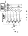
- a switch control circuit 300 supplies a control signal to a switch SW to open the switch SW when the power consumption of the expansion unit 31 exceeds a predetermined value, and stops power supply from the expansion unit 31 to the computer main body 21.
- the control signal output from the switch control circuit 300 is also supplied to a loudspeaker driver 321. a loudspeaker 313 is driven by the loudspeaker driver 321 in response to the control signal so as to generate an alarm.
- the arrangement of the switch control circuit 300 will be described in detail with reference to Fig. 7.
- the current values of voltages (+5 V, +12 V, -5 V, and -12 V) output from the constant voltage circuit 252c are measured by ammeters 301 to 304.
- the measured current values are supplied to the positive input terminals of corresponding comparators 305 to 309.
- Signals having predetermined reference current values Ir1 to Ir4 are supplied to the negative input terminals of the comparators 305 to 309, respectively.
- the outputs from the corresponding comparators 305 to 309 go to high level.
- the reference current values Ir1 to Ir4 are independently and appropriately determined in accordance with the capacity of the power supply 252.
- the measurement values of the ammeters 301 to 304 are supplied to an arithmetic circuit 310.
- the arithmetic circuit 310 calculates power consumption of each voltage from the measurement values of the ammeters 301 to 304 and the current values corresponding to the measurement values, and compares a sum of the obtained power consumption of the voltages with a predetermined set value.
- the arithmetic circuit 310 outputs a high-level signal when the sum of power consumption is larger than the set value.
- Outputs from the comparators 305 to 309 and the arithmetic circuit 310 are supplied to an OR circuit 311.
- An output from the OR circuit 311 is supplied to a control terminal of the switch SW, and the switch SW is opened when the output from the OR circuit 311 goes to high level. For this reason, a power of +15 V supplied from the power supply 252 to the power supply 120 is forcibly interrupted.
- the power supply 120 can be operated by a power supplied from the secondary battery 122.
- the computer main body 21 can be operated by an external power supply.
- the power supply 252 supplies a voltage (+15 V) to the computer main body 21 through the switch SW, a cable 34, the feeder plug 35, and the connector 29. In this case, operating voltages (+12 V, -12 V, +5 V, and -5 V) are not supplied to the respective components.
- the power supply 120 of the computer main body 21 supplies operating voltages (+12 V, -12 V, -9 V, +5 V, and -5 V) to the respective components of the computer main body 21 on the basis of the voltage (+15 V) from the power supply 120.
- a voltage (+5 V) from the power supply 120 is supplied to the expansion unit 31 through the connectors 26 and 45.
- the present invention is not limited to the above embodiment.
- the currents of the outputs (+5 V, +12 V, -5 V, and -12 V) from the constant voltage circuit 252c are measured.
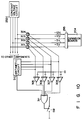
- the control circuit 300 may be constituted such that the ammeters 302 and 304, the comparators 306 and 308, and the arithmetic circuit 310 may be omitted except for the ammeters 301 and 303 and the comparators 305 and 307, as shown in Fig. 8.
- the current value of the power of +15 V supplied to the computer main body 21 is measured by an ammeter 321, and the resultant value may be supplied to the comparator 322 and the arithmetic circuit 310. In this case, when an output power from the power supply 252 exceeds the capacity of the power supply 252, power supply to the computer main body 21 can be stopped.
- the switch SW may be ON/OFF-controlled so as to check only the power consumption of the expansion board 204 which is the most decisive cause of a change in power consumption of the expansion unit 31.
- a wattmeter may be arranged in place of an ammeter, and a power of each voltage may be measured.
- the switch SW may be ON/OFF-controlled so as to compare the powers with a reference value.
- the switch SW may be constituted by, e.g., a relay switch, a transistor switch, a MOSFET, or the like.
- an expansion unit for supplying a power to a computer main body when power consumption of the expansion unit (including an expansion board) is increased, power supply to the computer main body is stopped. Therefore, powers can be stably supplied to the expansion board and components in the expansion unit.
Landscapes
- Engineering & Computer Science (AREA)
- Theoretical Computer Science (AREA)
- Physics & Mathematics (AREA)
- General Engineering & Computer Science (AREA)
- General Physics & Mathematics (AREA)
- Power Sources (AREA)
Applications Claiming Priority (2)
| Application Number | Priority Date | Filing Date | Title |
|---|---|---|---|
| JP278903/90 | 1990-10-19 | ||
| JP2278903A JPH04155417A (ja) | 1990-10-19 | 1990-10-19 | 機能拡張装置 |
Publications (3)
| Publication Number | Publication Date |
|---|---|
| EP0481461A2 true EP0481461A2 (fr) | 1992-04-22 |
| EP0481461A3 EP0481461A3 (en) | 1993-10-06 |
| EP0481461B1 EP0481461B1 (fr) | 1998-05-20 |
Family
ID=17603703
Family Applications (1)
| Application Number | Title | Priority Date | Filing Date |
|---|---|---|---|
| EP91117669A Expired - Lifetime EP0481461B1 (fr) | 1990-10-19 | 1991-10-16 | Unité d'expansion de fonction, capable de fournir l'alimentation à un ordinateur |
Country Status (5)
| Country | Link |
|---|---|
| US (2) | US5301334A (fr) |
| EP (1) | EP0481461B1 (fr) |
| JP (1) | JPH04155417A (fr) |
| KR (1) | KR940006801B1 (fr) |
| DE (1) | DE69129436T2 (fr) |
Cited By (2)
| Publication number | Priority date | Publication date | Assignee | Title |
|---|---|---|---|---|
| EP0635777A1 (fr) * | 1993-07-22 | 1995-01-25 | International Business Machines Corporation | Dispositif pour l'arrimage d'un ordinateur portatif |
| EP0838750A1 (fr) * | 1996-10-24 | 1998-04-29 | Fujitsu Limited | Appareil pour l'alimentation d'une unité d'extension par ordinateur portable |
Families Citing this family (35)
| Publication number | Priority date | Publication date | Assignee | Title |
|---|---|---|---|---|
| US5410712A (en) * | 1990-10-16 | 1995-04-25 | Kabushiki Kaisha Toshiba | Computer system equipped with extended unit including power supply |
| DE4230204A1 (de) * | 1991-09-09 | 1993-03-11 | Toshiba Kawasaki Kk | Netzteilsteuersystem fuer ein elektronisches geraet und daran angeschlossene erweiterungseinheit |
| WO1993009501A1 (fr) * | 1991-11-01 | 1993-05-13 | Yeh Keming W | Dispositif portable presentant une capacite de stockage de donnees et servant a transferer des donnees entre un ordinateur portable et un ordinateur de table |
| US5497464A (en) * | 1991-11-01 | 1996-03-05 | Yeh; Keming W. | Address mapping logic for transferring data between a peripheral device of a base function expander unit and a palmtop computer as if the peripheral was a peripheral of the computer |
| US5687089A (en) * | 1992-09-24 | 1997-11-11 | Data General Corporation | Drive regulator circuit board for a 3.50 inch disk drive |
| JPH06139182A (ja) * | 1992-10-27 | 1994-05-20 | Sony Corp | 情報処理装置、拡張基板、および拡張筐体システム |
| EP0626633B1 (fr) * | 1993-05-28 | 2001-03-14 | Sun Microsystems, Inc. | Commande d'alimentation par écran tactile dans un système informatique |
| JPH0793045A (ja) * | 1993-09-28 | 1995-04-07 | Fujitsu Ltd | 計算機の入出力装置 |
| JP2579436B2 (ja) * | 1994-06-16 | 1997-02-05 | インターナショナル・ビジネス・マシーンズ・コーポレイション | 携帯型コンピュータ用据置装置及びその制御方法 |
| JP2856675B2 (ja) * | 1994-06-27 | 1999-02-10 | 日本電気株式会社 | 携帯型情報処理機器とi/fを持つ無線選択呼出受信機 |
| US5530878A (en) * | 1994-11-17 | 1996-06-25 | Sun Microsystems, Inc. | Simplified power system with a single power converter providing low power consumption and a soft on/off feature |
| US5528756A (en) * | 1995-01-30 | 1996-06-18 | Elsag International N.V. | Method and apparatus for performing supervisory functions in digital systems and obtaining diagnostics thereof |
| US5958056A (en) * | 1995-05-26 | 1999-09-28 | Intel Corporation | Method and apparatus for selecting operating voltages in a backplane bus |
| US5838929A (en) * | 1995-06-01 | 1998-11-17 | Ast Research, Inc. | Upgrade CPU module with integral power supply |
| JPH0997127A (ja) * | 1995-09-29 | 1997-04-08 | Toshiba Corp | コンピュータシステム |
| JP3386640B2 (ja) * | 1995-09-29 | 2003-03-17 | 株式会社東芝 | コンピュータシステムおよびこのシステムで使用される拡張ユニット |
| CN2246821Y (zh) * | 1995-11-13 | 1997-02-05 | 马希光 | 笔记型电脑用扩充盒 |
| JPH10116133A (ja) | 1996-10-11 | 1998-05-06 | Fujitsu Ltd | 携帯情報機器 |
| JPH10124182A (ja) * | 1996-10-24 | 1998-05-15 | Fujitsu Ltd | 増設バッテリを装着可能な携帯型コンピュータ装置 |
| DE69729664T2 (de) * | 1996-11-04 | 2004-11-11 | Mobility Electronics, Inc., Scottsdale | System und verfahren zum anpassen von rechnerperipherievorrichtungen |
| US6058502A (en) * | 1997-09-03 | 2000-05-02 | Nec Corporation | Diagnostic system analyzing frequency spectrum of electric power for diagnosing integrated circuit, method and information storage medium storing computer program for the method |
| KR100265704B1 (ko) | 1997-10-17 | 2000-09-15 | 윤종용 | 케이블 매니저 시스템 및 그것을 구비하는 컴퓨터 |
| JP3280321B2 (ja) | 1998-09-14 | 2002-05-13 | 富士通株式会社 | 機能拡張装置及び電子機器システム |
| TW453620U (en) * | 1999-07-09 | 2001-09-01 | Asustek Comp Inc | External-connected auxiliary device of portable computer |
| US7987007B2 (en) * | 2002-03-18 | 2011-07-26 | Creative Technology Ltd | Memory module with audio playback mode |
| USD503408S1 (en) | 2002-03-18 | 2005-03-29 | Creative Technology Ltd. | Media player |
| US20060248251A1 (en) * | 2005-04-29 | 2006-11-02 | Tracy James L | Accessory docking station for a portable information device |
| US7719132B2 (en) | 2005-09-28 | 2010-05-18 | L3 Communications Corporation | Ruggedized mobile computing device |
| US20080028118A1 (en) * | 2006-07-31 | 2008-01-31 | Craig Peter Sayers | Portable dock for a portable computing system |
| US7689820B2 (en) * | 2006-09-27 | 2010-03-30 | L3 Communications Corporation | Rapid-boot computing device with dual operating systems |
| US8819483B2 (en) | 2006-09-27 | 2014-08-26 | L-3 Communications Corporation | Computing device with redundant, dissimilar operating systems |
| USD579451S1 (en) * | 2007-01-05 | 2008-10-28 | Oqo, Inc. | Computer docking assembly |
| US7624217B2 (en) * | 2007-02-12 | 2009-11-24 | Microsoft Corporation | Adaptive boot sequence |
| JP4960813B2 (ja) * | 2007-09-14 | 2012-06-27 | 株式会社リコー | 電力制御システム |
| CN204156972U (zh) * | 2014-10-31 | 2015-02-11 | 京东方科技集团股份有限公司 | 一种电视机和台式显示装置 |
Family Cites Families (20)
| Publication number | Priority date | Publication date | Assignee | Title |
|---|---|---|---|---|
| US3836813A (en) * | 1972-02-07 | 1974-09-17 | Raytheon Co | Power supply for use with a display system |
| US4161027A (en) * | 1976-10-04 | 1979-07-10 | Electric Power Research Institute, Inc. | Digital protection system for transmission lines and associated power equipment |
| JPS5838408Y2 (ja) * | 1977-10-14 | 1983-08-31 | ホーチキ株式会社 | 煙感知器の昇圧安定化電源装置 |
| US4312035A (en) * | 1979-06-18 | 1982-01-19 | Greene Richard E | Apparatus for controlling electrical power in a data processing system |
| US4748559A (en) * | 1979-08-09 | 1988-05-31 | Motorola, Inc. | Apparatus for reducing power consumed by a static microprocessor |
| US4503494A (en) * | 1980-06-26 | 1985-03-05 | Texas Instruments Incorporated | Non-volatile memory system |
| US4402059A (en) * | 1981-04-09 | 1983-08-30 | Westinghouse Electric Corp. | Load management terminal |
| JPS5955526A (ja) * | 1982-09-24 | 1984-03-30 | Sharp Corp | インタ−フエ−ス回路 |
| JPS6019220A (ja) * | 1983-07-13 | 1985-01-31 | Fujitsu Ltd | マイクロコンピユ−タ |
| US4560936A (en) * | 1984-12-24 | 1985-12-24 | Westinghouse Electric Corp. | Programmable controller system with failure indicator |
| US4769764A (en) * | 1986-08-11 | 1988-09-06 | Isaac Levanon | Modular computer system with portable travel unit |
| US4858162A (en) * | 1987-08-28 | 1989-08-15 | Connect Computer Company, Inc. | Method and apparatus used in mounting expansion cards |
| GB2214368B (en) * | 1987-12-30 | 1992-01-08 | Lre Relays & Electronics | Overload current cut-out circuit |
| GB2223116B (en) * | 1988-07-28 | 1992-08-19 | British Airways Plc | Transaction recording apparatus |
| US4977537A (en) * | 1988-09-23 | 1990-12-11 | Dallas Semiconductor Corporation | Dram nonvolatizer |
| US4903222A (en) * | 1988-10-14 | 1990-02-20 | Compag Computer Corporation | Arrangement of components in a laptop computer system |
| US5179710A (en) * | 1988-11-30 | 1993-01-12 | Laboratoire Europeen De Recherches Electroniques Avancees | Interface for amplifying logic signal from a signal line having a predetermined logic state to supply power to peripheral device |
| US5142684A (en) * | 1989-06-23 | 1992-08-25 | Hand Held Products, Inc. | Power conservation in microprocessor controlled devices |
| US5021679A (en) * | 1989-06-30 | 1991-06-04 | Poqet Computer Corporation | Power supply and oscillator for a computer system providing automatic selection of supply voltage and frequency |
| KR910015907A (ko) * | 1990-02-22 | 1991-09-30 | 정용문 | 과전압 방지 전원회로 |
-
1990
- 1990-10-19 JP JP2278903A patent/JPH04155417A/ja active Pending
-
1991
- 1991-10-16 US US07/777,190 patent/US5301334A/en not_active Expired - Fee Related
- 1991-10-16 DE DE69129436T patent/DE69129436T2/de not_active Expired - Fee Related
- 1991-10-16 EP EP91117669A patent/EP0481461B1/fr not_active Expired - Lifetime
- 1991-10-18 KR KR1019910018362A patent/KR940006801B1/ko not_active Expired - Fee Related
-
1994
- 1994-01-05 US US08/177,386 patent/US5430883A/en not_active Expired - Fee Related
Cited By (4)
| Publication number | Priority date | Publication date | Assignee | Title |
|---|---|---|---|---|
| EP0635777A1 (fr) * | 1993-07-22 | 1995-01-25 | International Business Machines Corporation | Dispositif pour l'arrimage d'un ordinateur portatif |
| EP0838750A1 (fr) * | 1996-10-24 | 1998-04-29 | Fujitsu Limited | Appareil pour l'alimentation d'une unité d'extension par ordinateur portable |
| US6160321A (en) * | 1996-10-24 | 2000-12-12 | Fujitsu Limited | Apparatus for supplying power from portable computer to extended station |
| EP1306738A3 (fr) * | 1996-10-24 | 2003-11-19 | Fujitsu Limited | Appareil pour l'alimentation d'une unité d'extension par ordinateur portable |
Also Published As
| Publication number | Publication date |
|---|---|
| US5301334A (en) | 1994-04-05 |
| DE69129436T2 (de) | 1998-11-05 |
| JPH04155417A (ja) | 1992-05-28 |
| EP0481461A3 (en) | 1993-10-06 |
| EP0481461B1 (fr) | 1998-05-20 |
| US5430883A (en) | 1995-07-04 |
| KR920008573A (ko) | 1992-05-28 |
| KR940006801B1 (ko) | 1994-07-27 |
| DE69129436D1 (de) | 1998-06-25 |
Similar Documents
| Publication | Publication Date | Title |
|---|---|---|
| US5301334A (en) | Function expansion unit capable of supplying power to computer | |
| US8051308B2 (en) | Display device with USB connectivity | |
| US5955797A (en) | Portable computer being powered by either a battery pack or an AC adapter | |
| EP0987620B1 (fr) | Appareil d'extension de fonction, appareil électronique et système électronique | |
| KR100395131B1 (ko) | 스마트 배터리의 실제 잔류 용량을 표시하기 위한 장치 및방법 | |
| KR101391758B1 (ko) | 배터리 모듈과 컴퓨터 시스템 및 그 전원공급방법 | |
| US7057309B2 (en) | Electrical apparatus, computer, power switching unit, and power switching method | |
| US20100060233A1 (en) | Charger with USB detection | |
| US20110279078A1 (en) | Charging circuit and method, electronic device, and power supply unit | |
| US20040064621A1 (en) | Powering a notebook across a USB interface | |
| US5606519A (en) | Portable electronic computer with removable disk drive | |
| US20080218129A1 (en) | Computer and battery charging method thereof | |
| US7366924B2 (en) | Systems and methods for disabling power management in a computer system | |
| JP2009157877A (ja) | 拡張装置およびこの拡張装置に接続される電子機器 | |
| EP1416605A1 (fr) | Dispositif électronique | |
| US7589519B2 (en) | Electronic apparatus with driving power having different voltage levels | |
| US20080203970A1 (en) | Battery-powered apparatus for portable system | |
| US20070096692A1 (en) | Electric power storage device with multiple voltage outputs | |
| US6766392B2 (en) | Electronic apparatus, control circuit for electronic apparatus, and method of controlling electronic apparatus | |
| KR100700532B1 (ko) | 범용 직렬 버스 포트의 연결 장치 인식 방법과 범용 직렬버스 어댑터 | |
| CN117335511A (zh) | 供电装置及其供电判断方法 | |
| EP1056034B1 (fr) | Adapteur de communication de données | |
| US6904531B2 (en) | Portable computer with low power consumption of a card bus controller thereof | |
| EP2290496A1 (fr) | Procédé et appareil pour l'alimentation d'un dispositif électronique | |
| JPS61251433A (ja) | 電子装置の充電式電池制御方式 |
Legal Events
| Date | Code | Title | Description |
|---|---|---|---|
| PUAI | Public reference made under article 153(3) epc to a published international application that has entered the european phase |
Free format text: ORIGINAL CODE: 0009012 |
|
| 17P | Request for examination filed |
Effective date: 19911113 |
|
| AK | Designated contracting states |
Kind code of ref document: A2 Designated state(s): DE FR GB |
|
| PUAL | Search report despatched |
Free format text: ORIGINAL CODE: 0009013 |
|
| AK | Designated contracting states |
Kind code of ref document: A3 Designated state(s): DE FR GB |
|
| 17Q | First examination report despatched |
Effective date: 19970311 |
|
| GRAG | Despatch of communication of intention to grant |
Free format text: ORIGINAL CODE: EPIDOS AGRA |
|
| GRAG | Despatch of communication of intention to grant |
Free format text: ORIGINAL CODE: EPIDOS AGRA |
|
| GRAG | Despatch of communication of intention to grant |
Free format text: ORIGINAL CODE: EPIDOS AGRA |
|
| GRAH | Despatch of communication of intention to grant a patent |
Free format text: ORIGINAL CODE: EPIDOS IGRA |
|
| GRAH | Despatch of communication of intention to grant a patent |
Free format text: ORIGINAL CODE: EPIDOS IGRA |
|
| GRAA | (expected) grant |
Free format text: ORIGINAL CODE: 0009210 |
|
| AK | Designated contracting states |
Kind code of ref document: B1 Designated state(s): DE FR GB |
|
| REF | Corresponds to: |
Ref document number: 69129436 Country of ref document: DE Date of ref document: 19980625 |
|
| ET | Fr: translation filed | ||
| PLBE | No opposition filed within time limit |
Free format text: ORIGINAL CODE: 0009261 |
|
| STAA | Information on the status of an ep patent application or granted ep patent |
Free format text: STATUS: NO OPPOSITION FILED WITHIN TIME LIMIT |
|
| 26N | No opposition filed | ||
| PGFP | Annual fee paid to national office [announced via postgrant information from national office to epo] |
Ref country code: DE Payment date: 20001009 Year of fee payment: 10 |
|
| PGFP | Annual fee paid to national office [announced via postgrant information from national office to epo] |
Ref country code: FR Payment date: 20001010 Year of fee payment: 10 |
|
| PGFP | Annual fee paid to national office [announced via postgrant information from national office to epo] |
Ref country code: GB Payment date: 20001011 Year of fee payment: 10 |
|
| PG25 | Lapsed in a contracting state [announced via postgrant information from national office to epo] |
Ref country code: GB Free format text: LAPSE BECAUSE OF NON-PAYMENT OF DUE FEES Effective date: 20011016 |
|
| REG | Reference to a national code |
Ref country code: GB Ref legal event code: IF02 |
|
| GBPC | Gb: european patent ceased through non-payment of renewal fee |
Effective date: 20011016 |
|
| PG25 | Lapsed in a contracting state [announced via postgrant information from national office to epo] |
Ref country code: FR Free format text: LAPSE BECAUSE OF NON-PAYMENT OF DUE FEES Effective date: 20020628 |
|
| PG25 | Lapsed in a contracting state [announced via postgrant information from national office to epo] |
Ref country code: DE Free format text: LAPSE BECAUSE OF NON-PAYMENT OF DUE FEES Effective date: 20020702 |
|
| REG | Reference to a national code |
Ref country code: FR Ref legal event code: ST |