EP0481797A2 - Contrôle de la hauteur des caractères pour des marqueurs de gouttelettes - Google Patents
Contrôle de la hauteur des caractères pour des marqueurs de gouttelettes Download PDFInfo
- Publication number
- EP0481797A2 EP0481797A2 EP91309609A EP91309609A EP0481797A2 EP 0481797 A2 EP0481797 A2 EP 0481797A2 EP 91309609 A EP91309609 A EP 91309609A EP 91309609 A EP91309609 A EP 91309609A EP 0481797 A2 EP0481797 A2 EP 0481797A2
- Authority
- EP
- European Patent Office
- Prior art keywords
- deflection
- drops
- flow parameter
- control means
- charge
- Prior art date
- Legal status (The legal status is an assumption and is not a legal conclusion. Google has not performed a legal analysis and makes no representation as to the accuracy of the status listed.)
- Granted
Links
- 239000003550 marker Substances 0.000 claims abstract description 25
- 239000000758 substrate Substances 0.000 claims abstract description 16
- 230000005684 electric field Effects 0.000 claims abstract description 13
- 230000004044 response Effects 0.000 claims abstract description 10
- 239000012530 fluid Substances 0.000 claims description 29
- 238000000034 method Methods 0.000 claims description 15
- 238000010586 diagram Methods 0.000 description 5
- 238000004422 calculation algorithm Methods 0.000 description 4
- 230000000694 effects Effects 0.000 description 4
- 238000005259 measurement Methods 0.000 description 4
- 230000001133 acceleration Effects 0.000 description 3
- 230000001419 dependent effect Effects 0.000 description 2
- 238000009795 derivation Methods 0.000 description 2
- 230000006870 function Effects 0.000 description 2
- 238000000935 solvent evaporation Methods 0.000 description 2
- 230000002411 adverse Effects 0.000 description 1
- 238000004364 calculation method Methods 0.000 description 1
- 239000012141 concentrate Substances 0.000 description 1
- 230000003247 decreasing effect Effects 0.000 description 1
- 238000013461 design Methods 0.000 description 1
- 230000007613 environmental effect Effects 0.000 description 1
- 238000007641 inkjet printing Methods 0.000 description 1
- 230000003993 interaction Effects 0.000 description 1
- 238000012423 maintenance Methods 0.000 description 1
- 238000012544 monitoring process Methods 0.000 description 1
- 230000035945 sensitivity Effects 0.000 description 1
- 239000002904 solvent Substances 0.000 description 1
- 238000012360 testing method Methods 0.000 description 1
- 238000012546 transfer Methods 0.000 description 1
Images


Classifications
-
- B—PERFORMING OPERATIONS; TRANSPORTING
- B41—PRINTING; LINING MACHINES; TYPEWRITERS; STAMPS
- B41J—TYPEWRITERS; SELECTIVE PRINTING MECHANISMS, i.e. MECHANISMS PRINTING OTHERWISE THAN FROM A FORME; CORRECTION OF TYPOGRAPHICAL ERRORS
- B41J2/00—Typewriters or selective printing mechanisms characterised by the printing or marking process for which they are designed
- B41J2/005—Typewriters or selective printing mechanisms characterised by the printing or marking process for which they are designed characterised by bringing liquid or particles selectively into contact with a printing material
- B41J2/01—Ink jet
- B41J2/07—Ink jet characterised by jet control
- B41J2/125—Sensors, e.g. deflection sensors
-
- B—PERFORMING OPERATIONS; TRANSPORTING
- B41—PRINTING; LINING MACHINES; TYPEWRITERS; STAMPS
- B41J—TYPEWRITERS; SELECTIVE PRINTING MECHANISMS, i.e. MECHANISMS PRINTING OTHERWISE THAN FROM A FORME; CORRECTION OF TYPOGRAPHICAL ERRORS
- B41J2/00—Typewriters or selective printing mechanisms characterised by the printing or marking process for which they are designed
- B41J2/005—Typewriters or selective printing mechanisms characterised by the printing or marking process for which they are designed characterised by bringing liquid or particles selectively into contact with a printing material
- B41J2/01—Ink jet
- B41J2/015—Ink jet characterised by the jet generation process
- B41J2/02—Ink jet characterised by the jet generation process generating a continuous ink jet
-
- B—PERFORMING OPERATIONS; TRANSPORTING
- B41—PRINTING; LINING MACHINES; TYPEWRITERS; STAMPS
- B41J—TYPEWRITERS; SELECTIVE PRINTING MECHANISMS, i.e. MECHANISMS PRINTING OTHERWISE THAN FROM A FORME; CORRECTION OF TYPOGRAPHICAL ERRORS
- B41J2/00—Typewriters or selective printing mechanisms characterised by the printing or marking process for which they are designed
- B41J2/005—Typewriters or selective printing mechanisms characterised by the printing or marking process for which they are designed characterised by bringing liquid or particles selectively into contact with a printing material
- B41J2/01—Ink jet
- B41J2/07—Ink jet characterised by jet control
- B41J2/075—Ink jet characterised by jet control for many-valued deflection
Definitions
- the present invention relates generally to the field of drop marking, including ink jet printing, and more particularly to controlling the height of characters produced thereby.
- Drop markers commonly utilise charge deflection printers of a type known in the art. Such known printers employ a piezoelectric element to break a constant stream of electrically conductive marking fluid, such as ink, into uniform drops. The drops are then electrically charged by charge means in the form of charging electrodes. The charged drops travel through an electric field created by a deflection electrode means. The influence of the deflection field on the charged drops alters their flight path.
- drop markers employ a pressurized distribution system, for creating a stream of marking fluid from a supply chamber to a nozzle, and a collection reservoir for capturing drops not intended to mark a target.
- the operation of most drop markers is controlled by a system microprocessor.
- a marking device capable of monitoring and adjusting the character height on an ongoing basis is desirable as it enhances marking quality. It is an object of the present invention to provide a control system capable of automatically adjusting the height of characters marked on a substrate by a drop marker, such as an ink jet printer, of the type in which a stream of electrically conductive marking fluid is created and is subsequently broken into drops, a charge means imparts an electric charge on selected drops, and a deflection electrode means creates an electric field to control the flight path of the charged drops dependant on a deflection voltage applied to the deflection electrode means.
- a drop marker such as an ink jet printer
- the characters marked on the substrate are maintained at a desired height by a control means which measures a flow parameter of the marking fluid and adjusts the deflection of the charged drops in response to such measured changes in the flow parameter of the marking fluid.
- the control means may be arranged to adjust the deflection of the charged drops by modifying the deflection voltage to the deflection electrode means.
- the control means may include a processor for altering the deflection voltage according to a linear approximation of empirically determined data relating the flow parameter to the deflection voltage.
- the control means may include a memory means having a look-up table relating the deflection voltage to a corresponding flow parameter, and the control means is arranged to adjust the deflection voltage responsive to measured changes in the flow parameter in accordance with the corresponding deflection voltage value in the look-up table.
- the flow parameter may be the velocity (V s ) of the stream
- the flow parameter may be the flight time (T FLT ) of the drops over a given distance
- K3 represents a constant for a given drop marker and n is a number from 2 to 3.
- the control means may alternatively or additionally be arranged to adjust the deflection of the charged drops by modifying the electric charge imparted to the selected drops by the charge means.
- the charge means may include a charge amplifier controlled by the control means to adjust the electric charge.
- the control means may include a processor for altering the gain of the charge amplifier according to a linear approximation of empirically determined data relating the flow parameter to the gain of the charge amplifier.
- the control means may include a memory means having a look-up table relating the gain of the charge amplifier to a corresponding flow parameter, and the control means is arranged to adjust the gain of the charge amplifier responsive to measured changes in the flow parameter in accordance with the corresponding gain value in the look-up table.
- the flow parameter may be the flight time (T FLT ) of the drops over a given distance
- K5 represents a constant for a given drop marker and n is a number from 2 to 3.
- the characters are maintained at a desired height by measuring a flow parameter of the fluid, and by adjusting the deflection of the charged drops in response to changes in the flow parameter.
- the deflection of the charged drops may be adjusted by varying the electrical field in response to changes in the flow parameter.
- the deflection of the charged drops may be adjusted by varying the charge on the drops in response to changes in the flow parameter.
- the invention provides a control system which has the capability of minimizing the influence on character height of external factors such as variations in printer operating temperature, because such external factors effect the flow parameters of the marking fluid.
- Any flow parameter of the marking fluid for instance flow velocity or flight time of the drops, is related to the viscosity of the marking fluid, which in turn is related to its temperature.
- the invention also provides a control system capable of operation without regard to changes in the physical characteristics of the marking fluid, because such changes which could affect character height, for instance solvent evaporation, also effect its viscosity which, as stated above, is related to the measured flow parameter of the marking fluid.
- the present invention provides dynamic adjustment of deflection sensitivity in drop markers, such as ink jet marking devices. It exploits the relationship between the voltage applied to the deflection electrodes of a drop marker and the height of the characters produced by periodically adjusting the deflection voltage dependent on measured changes in a flow parameter of the marking fluid, such as flow rate of the fluid, or flight time of drops of marking fluid to a print substrate. Alternatively, or additionally, it exploits the relationship between the charge applied to the drops and the deflection achieved by the voltage applied to the deflection electrodes, by periodically adjusting a charge amplifier to scale the charge applied to the drops dependent on measured changes in a flow parameter of the marking fluid, thereby controlling character height.
- the present invention determines a flow parameter, such as stream velocity and/or drop flight time, and periodically alters the deflection voltage and/or charge amplifier gain during printer operation.
- a flow parameter such as stream velocity and/or drop flight time
- an electronic controller in the form of a system microprocessor, is configured to measure the flow rate or flow time of electrically conductive ink, or other marking fluid, through an ink chamber 12.
- flow rate and flow time are inversely proportional to one another. Thus, either may be calculated if the other is known, provided the volume of chamber 12 is also known.
- Ink is forced through the system by a pressure source 14 which is connected to the top of chamber 12 and constitutes a means for creating a stream of the ink.
- Ink from the bottom of the chamber 12 is carried via a flexible conduit 16 to a print head 18 which has a vibrating piezoelectric element 20 for breaking the stream of ink into drops 21 as they leave an orifice 22 in a nozzle 24.
- a charge means in the form of a charge electrode 25 where they receive an electric charge.
- the magnitude of the charge is set by a charge amplifier 16 under control of the electronic controller 10.
- a set of deflection electrodes 28 is supplied with a high voltage to generate an electric field to act on the charged drops 21, causing them to be deflected to a desired location on the substrate. Drops that are not projected onto the substrate are caught by a collector 32 for subsequent reuse.
- the voltage on the deflection electrodes 28, and/or the gain of the charge amplifier 26, may be adjusted by the electronic controller 10 in response to measured changes in a flow parameter of the ink.
- any convenient flow parameter of the ink such as flow time or flow rate of the ink from the ink chamber 12 or through the conduit 16, or the flight time of the drops 21.
- flow parameter each of these various parameters is referred to collectively herein as a "flow parameter.”
- the Arway patent discloses one method for mesuring flow rate, however any flow parameter may be measured by any suitable method.
- any one of the flow parameters may be used to set constant character height by adjusting the deflection voltage on the deflection electrodes 28, and/or the gain of the charge amplifier 26.
- Charge amplifier gain and deflection voltage are each referred to collectively herein as an "adjustable parameter.”
- the present invention exploits the relationship between a flow parameter and an adjustable parameter for the purpose of maintaining constant character height.
- any of the various flow parameters may be used to control the value of either of the two adjustable parameters.
- the following discussion concentrates on the use of the flow rate to adjust deflection voltage. It will be readily apparent to one of ordinary skill in the art that this example can be easily modified to develop the relationships between any measured flow parameter and either adjustable parameter.
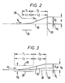
- Figure 2 illustrates the flight path 34 of an ink drop 21 as it passes through the electric field created by the deflection electrodes 28.
- the ink drops are deposited on a substrate 30, such as a sheet of paper.
- the flight path an ink drop would follow without the influence of the deflection field is shown by dashed line 38.
- V S represents the stream velocity of the marking fluid.
- V S is directly proportional to the flow rate, and can, therefore, be calculated by the electronic controller 10 after measurement of the flow rate.
- the deflection d is induced by the action of the deflection electrodes on a given drop of marking fluid.
- the deflection d comprises two components, the deflection d1 while the ink drop is traveling through the deflection field, and the deflection d2 after the drop exits the deflection field. Therefore, deflection d is the sum of deflections d1 and 2.
- L1 is the length of the deflection field
- L2 is the length from the end of the deflection field to the substrate 30.
- T1 the time the ink drop spends traveling through the deflection field
- T2 the time spent traveling to the substrate 30 after exiting the deflection field
- the flight time T of each drop 21 is the sum of T1 and T2.
- the electric field magnitude E is proportional to the voltage across the deflection electrodes 28 and will vary depending on the exact dimensions and spacing of these electrodes. For a given set of electrodes, this relationship can be readily computed.
- character height d is directly proportional to acceleration a induced on the ink drop, which is in turn proportional to the voltage supplied to the deflection electrodes of the drop marker.
- the character height d also varies inversely with the square of stream velocity V S . Therefore, uniform character height can be maintained, as V S changes, by determining V S and adjusting the deflection electrode voltage level to maintain the electric field strength so that acceleration a is adjusted proportionally to the square of V S .
- the electronic controller 10 exploits these relationships by determining the stream velocity V S and adjusting the voltage across the deflection electrodes 28 to maintain constant character height.
- Figure 5 shows an example of empirical data relating the measured flow parameter, that is in this case flow time, to the adjusted parameter, deflection voltage. Furthermore, as will be described hereinafter, a linear approximation of this relationship may be employed to set the value of the adjusted parameter over a realistic operating range.
- flow rate, flow time or flight time may be the measured flow parameter to practice the teachings of the present invention, depending on relative ease and/or expense of acquiring the measurement.
- Figure 3 shows that the total character height d CH is the difference between the deflection distance of the most deflected drop d H for a given character, and the deflection of the least deflected drop d L that is part of the same character.
- the teachings of the present invention are ultimately employed to maintain d CH constant. This goal is accomplished by controlling the deflection distance of each individual drop forming a character because the amount of deflection is proportional to the magnitude of drop charge and the voltage across the deflection electrodes.
- Figure 4 is a simplified flow diagram showing an algorithm suitable for use with a general purpose microprocessor for periodically determining one of the measured flow parameters previously described, and for using this information to control the adjustable parameter to maintain a desired character height. Assuming the automatic character height control feature is active, the user may select the desired character height for a given print job prior to operation of the drop marker.
- the algorithm can be executed periodically during printer operation or when the printer is idle. Experimental data demonstrates satisfactory results if the algorithm is executed at least every ten minutes during printer operation.
- the system microprocessor 10 measures one flow parameter.
- the teachings of the Arway patent or Stamer patent may be employed for measuring the flow rate of the marking fluid.
- the microprocessor may measure the flight time of ink drops by, for example, detecting the time taken for the drops to travel a known distance.
- the microprocessor may measure flow time of marking fluid in chamber 12. As previously described, the calculations of deflection voltage will differ only slightly, depending on which measured parameter is determined.
- the microprocessor determines the value of the adjustable parameter necessary to maintain constant character height for the measured parameter.
- the microprocessor may determine the value of the adjustable parameter by employing one of three different methods.
- the microprocessor calculates the proper value of the adjustable parameter according to the mathematical relationships developed above.
- the microprocessor calculates the value of the adjustable parameter based on a mathematical approximation of empirically measured data relating one measured flow parameter to one of the adjustable parameters.
- acceptable uniformity of character height may be achieved by employing an approximation of the relationship between the measured flow parameter, rather than by calculating the corresponding value of the adjustable parameter.
- the solid lines in Figure 5 show a best fit curve approximation of the relationship between flow time and deflection voltage in the range of deflection voltages between 3 kilovolts and 6 kilovolts, and flow times between sixty and seventy-five seconds.
- the relationship between some combinations of measured flow parameter and adjustable parameter allows adjustment based on a linear approximation over certain ranges.
- the dashed lines in Figure 5 show a linear approximation of the empirical relationship between flow time and deflection voltage. The slope of this line may be determined from mathematical analysis of the empirical data. After the slope has been determined, the microprocessor may be programmed to calculate the new deflection voltage value using linear approximation after measuring the prevailing flow time.
- An example of an algorithm suitable for calculating the new deflection voltage consists of initial measurement of the deflection voltage. This value is designated HV ref .
- the initial flow time T ref is measured.
- the actual flow time measured for a specific subsequent adjustment of the deflection voltage is designated T actual .
- a short term average of a number of recent flow time measurements may be used for T actual , depending on the desired accuracy in control of character height.
- HV actual represents the calculated value of the deflection voltage required to maintain constant character height for the flow time T actual .
- the calculated deflection voltage may be limited to minimum and maximum acceptable values in the event that the calculated value goes beyond the range over which the linear approximation is sufficiently accurate or goes beyond the range allowed for the head design.
- the microprocessor utilises a look-up table stored in system memory that relates a given measured flow parameter to the corresponding adjustable parameter.
- data for the look-up table may be obtained using either of the first two methods.
- the microprocessor sets the adjustable parameter to the level determined by method one, method two or method three.
- the microprocessor may be programmed to determine the measured flow parameter as often as desired for a specific application.
- character height is automatically controlled based on the prevailing flow rate, flow time or flight time, but without regard to external factors, such as operating temperature or any physical characteristic or a specific type of marking fluid.
Landscapes
- Particle Formation And Scattering Control In Inkjet Printers (AREA)
Applications Claiming Priority (2)
| Application Number | Priority Date | Filing Date | Title |
|---|---|---|---|
| US59964490A | 1990-10-18 | 1990-10-18 | |
| US599644 | 1990-10-18 |
Publications (3)
| Publication Number | Publication Date |
|---|---|
| EP0481797A2 true EP0481797A2 (fr) | 1992-04-22 |
| EP0481797A3 EP0481797A3 (en) | 1992-09-16 |
| EP0481797B1 EP0481797B1 (fr) | 1995-06-21 |
Family
ID=24400474
Family Applications (1)
| Application Number | Title | Priority Date | Filing Date |
|---|---|---|---|
| EP91309609A Expired - Lifetime EP0481797B1 (fr) | 1990-10-18 | 1991-10-17 | Contrôle de la hauteur des caractères pour des marqueurs de gouttelettes |
Country Status (5)
| Country | Link |
|---|---|
| US (1) | US5396273A (fr) |
| EP (1) | EP0481797B1 (fr) |
| JP (1) | JP2823977B2 (fr) |
| CA (1) | CA2049454C (fr) |
| DE (1) | DE69110611T2 (fr) |
Cited By (3)
| Publication number | Priority date | Publication date | Assignee | Title |
|---|---|---|---|---|
| GB2384352A (en) * | 1998-10-20 | 2003-07-23 | Hewlett Packard Co | Method for tuning print engine operating parameters |
| EP1452315A3 (fr) * | 2003-02-27 | 2005-08-31 | Sony Corporation | Appareil et procédé d'ejection de liquid |
| GB2575077A (en) * | 2018-06-28 | 2020-01-01 | Domino Uk Ltd | Stroke direction offset adjustment |
Families Citing this family (8)
| Publication number | Priority date | Publication date | Assignee | Title |
|---|---|---|---|---|
| US5517216A (en) * | 1992-07-28 | 1996-05-14 | Videojet Systems International, Inc. | Ink jet printer employing time of flight control system for ink jet printers |
| US6312104B1 (en) * | 1998-06-17 | 2001-11-06 | Xerox Corporation | Reduction of spot misplacement through electrostatic focusing of uncharged drops |
| US6883904B2 (en) * | 2002-04-24 | 2005-04-26 | Eastman Kodak Company | Apparatus and method for maintaining constant drop volumes in a continuous stream ink jet printer |
| US6615004B1 (en) | 2002-05-06 | 2003-09-02 | Hewlett-Packard Development Company, L.P. | Supplying marking fluid in an imaging system |
| US7207652B2 (en) * | 2003-10-17 | 2007-04-24 | Lexmark International, Inc. | Balanced satellite distributions |
| CN102173225A (zh) * | 2011-02-24 | 2011-09-07 | 上海泰威技术发展有限公司 | 大幅面平板式数码喷印中的高度控制装置 |
| CN111562447B (zh) * | 2020-05-18 | 2022-07-15 | 国网江苏省电力有限公司无锡供电分公司 | 一种高压架空输电线路电压等级识别系统及方法 |
| JP7542282B2 (ja) | 2020-08-04 | 2024-08-30 | ザ・リージェンツ・オブ・ザ・ユニバーシティ・オブ・ミシガン | 電気流体力学的およびエアロゾルの組合せ印刷 |
Family Cites Families (10)
| Publication number | Priority date | Publication date | Assignee | Title |
|---|---|---|---|---|
| US4015267A (en) * | 1973-07-19 | 1977-03-29 | Sharp Kabushiki Kaisha | Ink jet printer having air resistance distortion control |
| US4384295A (en) * | 1980-03-26 | 1983-05-17 | Cambridge Consultants Ltd. | Liquid jet printing apparatus using a raster of drops to effect printing |
| JPS57207071A (en) * | 1981-06-17 | 1982-12-18 | Ricoh Co Ltd | Ink jet recorder |
| JPS5831765A (ja) * | 1981-08-20 | 1983-02-24 | Ricoh Co Ltd | インクジエツト記録装置 |
| JPS60109851A (ja) * | 1983-11-18 | 1985-06-15 | Oki Electric Ind Co Ltd | インクジエツト記録装置 |
| GB2154321A (en) * | 1983-12-21 | 1985-09-04 | Post Office Headquarters The | Time of flight measurement for ink jet printers |
| US4555712A (en) * | 1984-08-03 | 1985-11-26 | Videojet Systems International, Inc. | Ink drop velocity control system |
| JPS6280053A (ja) * | 1985-10-04 | 1987-04-13 | Ricoh Co Ltd | マルチノズルインクジエツト記録装置 |
| US4847631A (en) * | 1986-07-16 | 1989-07-11 | Ricoh Company, Ltd. | Charge and deflection control type ink jet printer |
| US4827280A (en) * | 1988-08-09 | 1989-05-02 | A. B. Dick Company | Flow rate control system |
-
1991
- 1991-08-19 CA CA002049454A patent/CA2049454C/fr not_active Expired - Fee Related
- 1991-10-17 DE DE69110611T patent/DE69110611T2/de not_active Expired - Fee Related
- 1991-10-17 EP EP91309609A patent/EP0481797B1/fr not_active Expired - Lifetime
- 1991-10-18 JP JP3270777A patent/JP2823977B2/ja not_active Expired - Fee Related
-
1992
- 1992-01-30 US US07/827,896 patent/US5396273A/en not_active Expired - Fee Related
Cited By (9)
| Publication number | Priority date | Publication date | Assignee | Title |
|---|---|---|---|---|
| GB2384352A (en) * | 1998-10-20 | 2003-07-23 | Hewlett Packard Co | Method for tuning print engine operating parameters |
| GB2384352B (en) * | 1998-10-20 | 2003-10-01 | Hewlett Packard Co | Method for tuning print engine operating parameters |
| EP1452315A3 (fr) * | 2003-02-27 | 2005-08-31 | Sony Corporation | Appareil et procédé d'ejection de liquid |
| SG124284A1 (en) * | 2003-02-27 | 2006-08-30 | Sony Corp | Liquid discharge apparatus and method for discharging liquid |
| US7306309B2 (en) | 2003-02-27 | 2007-12-11 | Sony Corporation | Liquid discharge apparatus and method for discharging liquid |
| EP1932674A3 (fr) * | 2003-02-27 | 2008-11-26 | Sony Corporation | Appareil de décharge de liquide et procédé de décharge de liquide |
| EP1932673A3 (fr) * | 2003-02-27 | 2008-11-26 | Sony Corporation | Appareil de décharge de liquide et procédé de décharge de liquide |
| GB2575077A (en) * | 2018-06-28 | 2020-01-01 | Domino Uk Ltd | Stroke direction offset adjustment |
| WO2020002865A1 (fr) * | 2018-06-28 | 2020-01-02 | Domino Uk Limited | Réglage du décalage de direction de course |
Also Published As
| Publication number | Publication date |
|---|---|
| CA2049454A1 (fr) | 1992-04-19 |
| US5396273A (en) | 1995-03-07 |
| EP0481797A3 (en) | 1992-09-16 |
| JPH04259562A (ja) | 1992-09-16 |
| JP2823977B2 (ja) | 1998-11-11 |
| CA2049454C (fr) | 1999-01-05 |
| DE69110611T2 (de) | 1996-01-04 |
| DE69110611D1 (de) | 1995-07-27 |
| EP0481797B1 (fr) | 1995-06-21 |
Similar Documents
| Publication | Publication Date | Title |
|---|---|---|
| EP0607419B1 (fr) | Imprimante a jet d'encre a frequence variable | |
| US6561614B1 (en) | Ink system characteristic identification | |
| US3761941A (en) | Phase control for a drop generating and charging system | |
| EP0481797B1 (fr) | Contrôle de la hauteur des caractères pour des marqueurs de gouttelettes | |
| US4417256A (en) | Break-off uniformity maintenance | |
| US4337468A (en) | Method and device for controlling concentration of ink for ink-jet printer | |
| EP0536000A2 (fr) | Marquage à gouttes d'encre avec contrôle de la qualité des gouttes | |
| CA1084100A (fr) | Appareil permettant de controler la formation et la forme des gouttelettes dans une imprimante par jets d'encre, et methode de fonctionnement | |
| CA1156710A (fr) | Dispositif pour stabiliser le point de separation de gouttelettes | |
| US5434609A (en) | Deflection system for deflecting charged particles | |
| CA1156711A (fr) | Dispositif a boucle fermee pour compenser les effets aerodynamiques subis par des gouttelettes d'encre | |
| US5523778A (en) | Segmented charge tunnel for drop charging in a printhead | |
| EP0744292B1 (fr) | Procédé et appareil de réglage automatique de la tension de commande des buses dans une imprimante à jet d'encre | |
| JPH0691879A (ja) | インクジェットプリンタにおける印刷歪みを補正する方法および装置 | |
| US4394663A (en) | Ink jet printing apparatus | |
| US5517216A (en) | Ink jet printer employing time of flight control system for ink jet printers | |
| WO1996008374A1 (fr) | Procede et dispositif d'impression a jet d'encre continu | |
| US4688047A (en) | Method and apparatus for sensing satellite ink drop charge and adjusting ink pressure | |
| JPH05338201A (ja) | インクジェット記録装置 | |
| JPH11245390A (ja) | インクジェット記録装置 | |
| JPH09201980A (ja) | 流量測定機構およびこれを用いた印字装置 | |
| JP2012061760A (ja) | 画像形成装置、画像形成装置の制御方法および制御プログラム | |
| JPS56115274A (en) | Deflection controlling method for deflection control ink-jet recording | |
| JPH11207964A (ja) | 連続式インクジェットプリンタにおけるピエゾ素子の駆動方法及び連続式インクジェットプリンタ | |
| JPH08197738A (ja) | インクジェット記録装置 |
Legal Events
| Date | Code | Title | Description |
|---|---|---|---|
| PUAI | Public reference made under article 153(3) epc to a published international application that has entered the european phase |
Free format text: ORIGINAL CODE: 0009012 |
|
| AK | Designated contracting states |
Kind code of ref document: A2 Designated state(s): BE CH DE DK FR GB IT LI NL |
|
| PUAL | Search report despatched |
Free format text: ORIGINAL CODE: 0009013 |
|
| AK | Designated contracting states |
Kind code of ref document: A3 Designated state(s): BE CH DE DK FR GB IT LI NL |
|
| 17P | Request for examination filed |
Effective date: 19921027 |
|
| 17Q | First examination report despatched |
Effective date: 19940427 |
|
| GRAA | (expected) grant |
Free format text: ORIGINAL CODE: 0009210 |
|
| AK | Designated contracting states |
Kind code of ref document: B1 Designated state(s): BE CH DE DK FR GB IT LI NL |
|
| PG25 | Lapsed in a contracting state [announced via postgrant information from national office to epo] |
Ref country code: LI Effective date: 19950621 Ref country code: DK Effective date: 19950621 Ref country code: CH Effective date: 19950621 Ref country code: BE Effective date: 19950621 |
|
| ITF | It: translation for a ep patent filed | ||
| RAP2 | Party data changed (patent owner data changed or rights of a patent transferred) |
Owner name: VIDEOJET SYSTEMS INTERNATIONAL, INC. |
|
| REF | Corresponds to: |
Ref document number: 69110611 Country of ref document: DE Date of ref document: 19950727 |
|
| NLT2 | Nl: modifications (of names), taken from the european patent patent bulletin |
Owner name: VIDEOJET SYSTEMS INTERNATIONAL, INC. |
|
| REG | Reference to a national code |
Ref country code: CH Ref legal event code: PL |
|
| ET | Fr: translation filed | ||
| PLBE | No opposition filed within time limit |
Free format text: ORIGINAL CODE: 0009261 |
|
| STAA | Information on the status of an ep patent application or granted ep patent |
Free format text: STATUS: NO OPPOSITION FILED WITHIN TIME LIMIT |
|
| 26N | No opposition filed | ||
| PGFP | Annual fee paid to national office [announced via postgrant information from national office to epo] |
Ref country code: GB Payment date: 20011008 Year of fee payment: 11 |
|
| PGFP | Annual fee paid to national office [announced via postgrant information from national office to epo] |
Ref country code: FR Payment date: 20011010 Year of fee payment: 11 |
|
| PGFP | Annual fee paid to national office [announced via postgrant information from national office to epo] |
Ref country code: DE Payment date: 20011029 Year of fee payment: 11 |
|
| PGFP | Annual fee paid to national office [announced via postgrant information from national office to epo] |
Ref country code: NL Payment date: 20011031 Year of fee payment: 11 |
|
| REG | Reference to a national code |
Ref country code: GB Ref legal event code: IF02 |
|
| PG25 | Lapsed in a contracting state [announced via postgrant information from national office to epo] |
Ref country code: GB Free format text: LAPSE BECAUSE OF NON-PAYMENT OF DUE FEES Effective date: 20021017 |
|
| PG25 | Lapsed in a contracting state [announced via postgrant information from national office to epo] |
Ref country code: NL Free format text: LAPSE BECAUSE OF NON-PAYMENT OF DUE FEES Effective date: 20030501 Ref country code: DE Free format text: LAPSE BECAUSE OF NON-PAYMENT OF DUE FEES Effective date: 20030501 |
|
| GBPC | Gb: european patent ceased through non-payment of renewal fee |
Effective date: 20021017 |
|
| PG25 | Lapsed in a contracting state [announced via postgrant information from national office to epo] |
Ref country code: FR Free format text: LAPSE BECAUSE OF NON-PAYMENT OF DUE FEES Effective date: 20030630 |
|
| NLV4 | Nl: lapsed or anulled due to non-payment of the annual fee |
Effective date: 20030501 |
|
| REG | Reference to a national code |
Ref country code: FR Ref legal event code: ST |
|
| PG25 | Lapsed in a contracting state [announced via postgrant information from national office to epo] |
Ref country code: IT Free format text: LAPSE BECAUSE OF NON-PAYMENT OF DUE FEES;WARNING: LAPSES OF ITALIAN PATENTS WITH EFFECTIVE DATE BEFORE 2007 MAY HAVE OCCURRED AT ANY TIME BEFORE 2007. THE CORRECT EFFECTIVE DATE MAY BE DIFFERENT FROM THE ONE RECORDED. Effective date: 20051017 |