EP0481936A2 - Verfahren und Gerät zum kontinuierlichen Kontrollieren des Auflegedruckes an Werkstücken in einer beidseitigen Läppmaschine - Google Patents
Verfahren und Gerät zum kontinuierlichen Kontrollieren des Auflegedruckes an Werkstücken in einer beidseitigen Läppmaschine Download PDFInfo
- Publication number
- EP0481936A2 EP0481936A2 EP91830441A EP91830441A EP0481936A2 EP 0481936 A2 EP0481936 A2 EP 0481936A2 EP 91830441 A EP91830441 A EP 91830441A EP 91830441 A EP91830441 A EP 91830441A EP 0481936 A2 EP0481936 A2 EP 0481936A2
- Authority
- EP
- European Patent Office
- Prior art keywords
- plate
- pressure
- processing unit
- central processing
- controlling
- Prior art date
- Legal status (The legal status is an assumption and is not a legal conclusion. Google has not performed a legal analysis and makes no representation as to the accuracy of the status listed.)
- Withdrawn
Links
Images


Classifications
-
- B—PERFORMING OPERATIONS; TRANSPORTING
- B24—GRINDING; POLISHING
- B24B—MACHINES, DEVICES, OR PROCESSES FOR GRINDING OR POLISHING; DRESSING OR CONDITIONING OF ABRADING SURFACES; FEEDING OF GRINDING, POLISHING, OR LAPPING AGENTS
- B24B37/00—Lapping machines or devices; Accessories
- B24B37/04—Lapping machines or devices; Accessories designed for working plane surfaces
- B24B37/07—Lapping machines or devices; Accessories designed for working plane surfaces characterised by the movement of the work or lapping tool
- B24B37/08—Lapping machines or devices; Accessories designed for working plane surfaces characterised by the movement of the work or lapping tool for double side lapping
-
- B—PERFORMING OPERATIONS; TRANSPORTING
- B24—GRINDING; POLISHING
- B24B—MACHINES, DEVICES, OR PROCESSES FOR GRINDING OR POLISHING; DRESSING OR CONDITIONING OF ABRADING SURFACES; FEEDING OF GRINDING, POLISHING, OR LAPPING AGENTS
- B24B49/00—Measuring or gauging equipment for controlling the feed movement of the grinding tool or work; Arrangements of indicating or measuring equipment, e.g. for indicating the start of the grinding operation
- B24B49/02—Measuring or gauging equipment for controlling the feed movement of the grinding tool or work; Arrangements of indicating or measuring equipment, e.g. for indicating the start of the grinding operation according to the instantaneous size and required size of the workpiece acted upon, the measuring or gauging being continuous or intermittent
-
- B—PERFORMING OPERATIONS; TRANSPORTING
- B24—GRINDING; POLISHING
- B24B—MACHINES, DEVICES, OR PROCESSES FOR GRINDING OR POLISHING; DRESSING OR CONDITIONING OF ABRADING SURFACES; FEEDING OF GRINDING, POLISHING, OR LAPPING AGENTS
- B24B49/00—Measuring or gauging equipment for controlling the feed movement of the grinding tool or work; Arrangements of indicating or measuring equipment, e.g. for indicating the start of the grinding operation
- B24B49/16—Measuring or gauging equipment for controlling the feed movement of the grinding tool or work; Arrangements of indicating or measuring equipment, e.g. for indicating the start of the grinding operation taking regard of the load
Definitions
- the present invention relates to the field of the superfinishing machines and, more particularly, it concerns a method of and an apparatus for continuously controlling the pressure applied on workpieces in a double-plate lapping machine.
- the progressive lightening of the upper plate due to the wear thereof is taken into account as a very important factor in the lapping operations.
- Such lightening can cause the pressure on the workpieces to vary so as to affect negatively the machining of the workpieces.
- this negative circumstance is as much more detrimental to the qualitative effects as higher is the required precision degree of the lapping operation.
- said known apparatus can be classified in three different ways according to the operating mode thereof.
- the first one is a mechanical counterweight system balancing the plate. This system is not accurate because the counterweight is unbalanced as the plate is worn out, and the change in the operating pressure is considerable end cannot be easily controlled.
- Another known system makes use of a pneumatic circuit having the function of restoring the worn out plate.
- the plate is aiming at "floating" so that the pressure is still not uniform.
- This invention seeks to provide a method and an apparatus allowing the position of the plate and then the operating pressure of the same to be continuously controlled even for very small differential pressures of the order of 1 kg corresponding to about 1/100 of the weight of the upper plate.
- a method of controlling the position of the upper plate in a lapping machine including the step of mechanically driving the plate which is axially shifted under control of a linear transducer connected to said plate and responsive to a central processing unit which is drivingly connected to said axial drive of the plate and to a pressure measuring unit sensing the bearing pressure of the plate and connected between the plate and a servomotor driving said axial shift.
- Such mechanical axial drive system includes a micrometrical feeding device formed of a ball bearing screw connected to the plate and a lead nut drivingly connected to said ball bearing screw and driven by the servomotor when the transducer feeds a control signal which is compared with the setting data measured by the pressure measuring unit and fed to the central processing unit.
- the pressure measuring unit displays the measured values on a digital display.
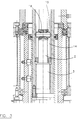
- the upper plate of the lapping machine is designated by 1.
- Such plate rotates about its axis to carry out a lapping operation in cooperation with the lower plate not shown because it is not a part of the present invention.
- the rotary motion plate 1 can axially move to apply the lapping pressure P (decanewton) to the workpieces.
- Such axial shift is carried out by means of a micrometrical mechanical drive by a ball bearing screw 2 engaged in the lead nut 3.
- the latter is carried by the stationary frame 4A of the lapping machine and is rotated by an electronic switching brushless servomotor 7 as better described afterwards.
- the pressure measuring unit 5 is interconnected between servomotor 7 and lead nut 3 and will not be described as it is well known.
- the controlling method is as follows:
- Working parameters among which pressure P and height H of the workpiece, are set in the central processing unit 10 which may be a PLC/microprocessor.
- Parameter signals are amplified by the proportional integral differential (P.I.D.) amplifier designated by 9 and fed through the control power supply 8 to servomotor 7 driving plate 1 to move downwards by the system formed of screw 2 and lead nut 3 which will be described in detail below.
- P.I.D. proportional integral differential
- the position of plate 1 with respect to the workpieces is detected by the linear transducer 4.
- the pressure measuring unit senses the pressure value and shows it on video-display 6, feeding also such data to block 10 to automatically adjust the pressure.
- servomotor 7 carries the drive shaft 11 connected through key 12 to the hollow shaft 13, in which two elongated, diametrally opposed slots are formed. Pins 15 carried by the draft peg integral with ball bearing screw 2 connected to lead nut 3 already described in Fig. 1 slide into said slots.
- the rotation of hollow shaft 13 causes correspondingly ball bearing screw 2 and lead nut 3 to rotate, the latter in turn causing shaft 18 carrying at its lower end plate 1 to axially move.
- plate 1 is rotated about geometric axis H of shaft 18 by a drive belt 19 engaging pulley 20 integralwith the rotating column 21 within bellow 23 mounted between case 22 and plate 1.
Landscapes
- Engineering & Computer Science (AREA)
- Mechanical Engineering (AREA)
- Finish Polishing, Edge Sharpening, And Grinding By Specific Grinding Devices (AREA)
Applications Claiming Priority (2)
| Application Number | Priority Date | Filing Date | Title |
|---|---|---|---|
| IT4838290 | 1990-10-17 | ||
| IT04838290A IT1244131B (it) | 1990-10-17 | 1990-10-17 | Metodo e dispositivo per il controllo continuo della spinta applicata sui pezzi in lavorazione in una macchina lappatrice a doppio plateau. |
Publications (2)
| Publication Number | Publication Date |
|---|---|
| EP0481936A2 true EP0481936A2 (de) | 1992-04-22 |
| EP0481936A3 EP0481936A3 (en) | 1992-08-26 |
Family
ID=11266231
Family Applications (1)
| Application Number | Title | Priority Date | Filing Date |
|---|---|---|---|
| EP19910830441 Withdrawn EP0481936A3 (en) | 1990-10-17 | 1991-10-16 | Method of and apparatus for continuously controlling the pressure applied on workpieces in a double-plate lapping machine |
Country Status (2)
| Country | Link |
|---|---|
| EP (1) | EP0481936A3 (de) |
| IT (1) | IT1244131B (de) |
Cited By (4)
| Publication number | Priority date | Publication date | Assignee | Title |
|---|---|---|---|---|
| EP0517640A1 (de) * | 1991-06-04 | 1992-12-09 | SEVA, société dite, | Feinstbearbeitungsmaschine mit pneumatischer Kraftsteuerung des Werkzeuges |
| EP0967048A1 (de) * | 1998-06-22 | 1999-12-29 | Speedfam Co., Ltd. | Doppelseitige Poliervorrichtung |
| US7125313B2 (en) | 2003-02-25 | 2006-10-24 | Novellus Systems, Inc. | Apparatus and method for abrading a workpiece |
| CN101968400A (zh) * | 2010-03-10 | 2011-02-09 | 慧源检测技术(上海)有限公司 | 一种轨迹球测试装置及其测试方法 |
Family Cites Families (4)
| Publication number | Priority date | Publication date | Assignee | Title |
|---|---|---|---|---|
| DE2950881C2 (de) * | 1979-12-18 | 1983-06-01 | Fa. Peter Wolters, 2370 Rendsburg | Steuereinrichtung für den Bearbeitungsdruck an Läpp-, Hon- und Schleißmaschinen |
| DE3818159A1 (de) * | 1988-05-28 | 1989-11-30 | Wolters Peter Fa | Verfahren und vorrichtung zur steuerung des betriebs von hon- oder schleifmaschinen |
| US4873792A (en) * | 1988-06-01 | 1989-10-17 | Buehler, Ltd. | Polishing apparatus |
| US5010491A (en) * | 1988-12-27 | 1991-04-23 | International Business Machines Corp. | Automated system for machining parts to close tolerances |
-
1990
- 1990-10-17 IT IT04838290A patent/IT1244131B/it active IP Right Grant
-
1991
- 1991-10-16 EP EP19910830441 patent/EP0481936A3/en not_active Withdrawn
Cited By (4)
| Publication number | Priority date | Publication date | Assignee | Title |
|---|---|---|---|---|
| EP0517640A1 (de) * | 1991-06-04 | 1992-12-09 | SEVA, société dite, | Feinstbearbeitungsmaschine mit pneumatischer Kraftsteuerung des Werkzeuges |
| EP0967048A1 (de) * | 1998-06-22 | 1999-12-29 | Speedfam Co., Ltd. | Doppelseitige Poliervorrichtung |
| US7125313B2 (en) | 2003-02-25 | 2006-10-24 | Novellus Systems, Inc. | Apparatus and method for abrading a workpiece |
| CN101968400A (zh) * | 2010-03-10 | 2011-02-09 | 慧源检测技术(上海)有限公司 | 一种轨迹球测试装置及其测试方法 |
Also Published As
| Publication number | Publication date |
|---|---|
| IT9048382A0 (it) | 1990-10-17 |
| EP0481936A3 (en) | 1992-08-26 |
| IT9048382A1 (it) | 1992-04-17 |
| IT1244131B (it) | 1994-07-08 |
Similar Documents
| Publication | Publication Date | Title |
|---|---|---|
| US4573379A (en) | Apparatus for producing an adjusting torque | |
| US4669359A (en) | Positioning system | |
| KR910003501B1 (ko) | 제분기의 분쇄간극 조절장치 | |
| US4698773A (en) | Adaptive feed rate override system for a milling machine | |
| US4432260A (en) | Method and apparatus for controlling the feeding of a bandsaw blade of horizontal bandsaw machines | |
| JPH0259252A (ja) | 計算機制御工作機械の制御手段 | |
| KR100966936B1 (ko) | 인덱싱 장치 | |
| US7828627B2 (en) | O.D. centerless grinding machine | |
| GB1472635A (en) | Control apparatus for imposing a programme of speeds of relative displacement between a workpiece and a tool | |
| US5197230A (en) | Finish-machining machine | |
| US4823061A (en) | Stone expansion control for a honing machine | |
| US4790545A (en) | Workpart centering mechanism for a chuck | |
| WO1994003788A1 (en) | Apparatus for the dynamical balancing of a rotating body | |
| US4209273A (en) | Machine tool speed control system | |
| US5741172A (en) | Drive and control device and related process for a grinding machine | |
| US3961757A (en) | Method and machine for refining wood chippings, shavings, paper pulp and the like | |
| JPH01182011A (ja) | スライシングマシンおよびその制御方法 | |
| US4102082A (en) | Cam grinding apparatus with means to maintain the grinding speed constant | |
| KR920006507B1 (ko) | 와이어 방전 가공장치 | |
| EP0481935A2 (de) | Verfahren und Gerät zum Kontrollieren von Werkstücken auf einer zweiseitigen Läppmaschine nach deren Bearbeitung | |
| JP3305076B2 (ja) | 切削加工装置 | |
| US4085551A (en) | Grinding machines | |
| IT9048382A1 (it) | Metodo e dispositivo per il controllo continuo della spinta applicata sui pezzi in lavorazione in una macchina lappatrice a doppio plateau. | |
| JPH04367400A (ja) | プレス制御方法及びその装置 | |
| KR100600235B1 (ko) | 공작기계용 인덱스 테이블 구동장치 |
Legal Events
| Date | Code | Title | Description |
|---|---|---|---|
| PUAI | Public reference made under article 153(3) epc to a published international application that has entered the european phase |
Free format text: ORIGINAL CODE: 0009012 |
|
| AK | Designated contracting states |
Kind code of ref document: A2 Designated state(s): CH DE FR GB LI |
|
| PUAL | Search report despatched |
Free format text: ORIGINAL CODE: 0009013 |
|
| AK | Designated contracting states |
Kind code of ref document: A3 Designated state(s): CH DE FR GB LI |
|
| STAA | Information on the status of an ep patent application or granted ep patent |
Free format text: STATUS: THE APPLICATION IS DEEMED TO BE WITHDRAWN |
|
| 18D | Application deemed to be withdrawn |
Effective date: 19930510 |