EP0482799A1 - Buse de fluidisation unidirectionnelle et lit fluidifié utilisant celle-ci - Google Patents
Buse de fluidisation unidirectionnelle et lit fluidifié utilisant celle-ci Download PDFInfo
- Publication number
- EP0482799A1 EP0482799A1 EP91309322A EP91309322A EP0482799A1 EP 0482799 A1 EP0482799 A1 EP 0482799A1 EP 91309322 A EP91309322 A EP 91309322A EP 91309322 A EP91309322 A EP 91309322A EP 0482799 A1 EP0482799 A1 EP 0482799A1
- Authority
- EP
- European Patent Office
- Prior art keywords
- nozzle
- particulate material
- opening
- plate
- plenum
- Prior art date
- Legal status (The legal status is an assumption and is not a legal conclusion. Google has not performed a legal analysis and makes no representation as to the accuracy of the status listed.)
- Withdrawn
Links
- 238000005243 fluidization Methods 0.000 title claims description 8
- 239000011236 particulate material Substances 0.000 claims abstract description 26
- 239000000463 material Substances 0.000 description 16
- 239000000446 fuel Substances 0.000 description 6
- 230000005587 bubbling Effects 0.000 description 5
- 239000012530 fluid Substances 0.000 description 5
- 239000003463 adsorbent Substances 0.000 description 4
- 239000003245 coal Substances 0.000 description 4
- 238000002485 combustion reaction Methods 0.000 description 4
- 238000007599 discharging Methods 0.000 description 4
- 239000007787 solid Substances 0.000 description 4
- NINIDFKCEFEMDL-UHFFFAOYSA-N Sulfur Chemical compound [S] NINIDFKCEFEMDL-UHFFFAOYSA-N 0.000 description 3
- MWUXSHHQAYIFBG-UHFFFAOYSA-N nitrogen oxide Inorganic materials O=[N] MWUXSHHQAYIFBG-UHFFFAOYSA-N 0.000 description 3
- 229910052717 sulfur Inorganic materials 0.000 description 3
- 239000011593 sulfur Substances 0.000 description 3
- 239000007789 gas Substances 0.000 description 2
- 230000005484 gravity Effects 0.000 description 2
- 238000000034 method Methods 0.000 description 2
- 239000002245 particle Substances 0.000 description 2
- 235000019738 Limestone Nutrition 0.000 description 1
- 239000002802 bituminous coal Substances 0.000 description 1
- 239000000567 combustion gas Substances 0.000 description 1
- 239000002803 fossil fuel Substances 0.000 description 1
- 239000006028 limestone Substances 0.000 description 1
- 239000000203 mixture Substances 0.000 description 1
- 229920006395 saturated elastomer Polymers 0.000 description 1
- 238000001179 sorption measurement Methods 0.000 description 1
- XLYOFNOQVPJJNP-UHFFFAOYSA-N water Substances O XLYOFNOQVPJJNP-UHFFFAOYSA-N 0.000 description 1
- 238000003466 welding Methods 0.000 description 1
Images

Classifications
-
- B—PERFORMING OPERATIONS; TRANSPORTING
- B01—PHYSICAL OR CHEMICAL PROCESSES OR APPARATUS IN GENERAL
- B01J—CHEMICAL OR PHYSICAL PROCESSES, e.g. CATALYSIS OR COLLOID CHEMISTRY; THEIR RELEVANT APPARATUS
- B01J8/00—Chemical or physical processes in general, conducted in the presence of fluids and solid particles; Apparatus for such processes
- B01J8/18—Chemical or physical processes in general, conducted in the presence of fluids and solid particles; Apparatus for such processes with fluidised particles
- B01J8/1818—Feeding of the fluidising gas
-
- F—MECHANICAL ENGINEERING; LIGHTING; HEATING; WEAPONS; BLASTING
- F23—COMBUSTION APPARATUS; COMBUSTION PROCESSES
- F23C—METHODS OR APPARATUS FOR COMBUSTION USING FLUID FUEL OR SOLID FUEL SUSPENDED IN A CARRIER GAS OR AIR
- F23C10/00—Fluidised bed combustion apparatus
- F23C10/18—Details; Accessories
- F23C10/20—Inlets for fluidisation air, e.g. grids; Bottoms
Definitions
- This invention relates to a fluidized nozzle and a fluidized bed system utilizing same and, more particularly, to such a nozzle and system in which a bed of particulate material in an enclosed space is fluidized by the introduction of air into the bed through the nozzle.
- Fluidized bed reactors such as gasifiers, steam generators, combustors, and the like, are well known.
- pressurized air or other fluidizing media is passed, via a plurality of nozzles, through a bed of particulate material, including a fossil fuel such as coal and an adsorbent for the sulfur generated as a result of combustion of the coal, to fluidize the bed and to promote the combustion of the fuel at a relatively low temperature.
- the entrained particulate solids are separated externally of the bed and recycled back into the bed.
- the heat produced by the fluidized bed is utilized in various applications such as the generation of steam, which results in an attractive combination of high heat release, high sulfur adsorption, low nitrogen oxides emissions and fuel flexibility.
- the most typical fluidized bed reactor is commonly referred to as a "bubbling" fluidized bed in which the bed of particulate material has a relatively high density and a well-defined, or discrete, upper surface.
- fluidized bed reactors utilize a "circulating" fluidized bed. According to these processes, the fluidized bed density is well below that of a typical bubbling fluidized bed, the air velocity is greater than that of a bubbling bed and the air entrains a substantial amount of particulate solids and is substantially saturated therewith.
- an air plenum is disposed below an air distributor plate, or grid, for supplying pressurized air to a plurality of air nozzles supported by the plate.
- the nozzles extend above the plate and into the bed and discharge the air into the bed.
- the solids from the bed can backflow, or weep, through the nozzles and into the air plenum especially in connection with circulating fluidized beds when the unit is suddenly shut down while operating at full loads.
- the solids will accumulate in the air plenum and block air flow through the nozzles.
- the nozzles In order to minimize the backflow, the nozzles have to be designed with great care to arrive at the best discharge angle associated with the nozzle diameter, length, bed material characteristics, etc. This is time consuming and expensive, and adds to the overall costs of the system.
- the fluidization nozzle of the present invention is mounted on a distributor plate which supports a bed of particulate material.
- the nozzle receives air flow from a plenum located below the plate and distributes the air into the bed.
- the nozzle includes a one-way valve connected for preventing backflow of the bed material to the plenum.
- the fluidization nozzle of the present invention will be described in connection with a heat exchanger in the form of a boiler, a combustor, a process reactor or any similar type device utilizing a bubbling fluidized bed.
- the heat exchanger includes an enclosure 10 consisting of a front wall 12, a rear wall 14, and two sidewalls, one of which is shown by the reference numeral 16.
- Each wall may be formed by a plurality of vertically-extending tubes 18 disposed in a spaced, parallel relationship and connected together by a plurality of elongated fins 20 extending for the entire lengths of the tubes and connected to diametrically opposed surfaces of the tubes in a conventional manner.
- the upper portion of the enclosure 10 is not shown for the convenience of presentation, it being understood that it consists of a convection section, a roof and an outlet for allowing the combustion gases to discharge, also in a conventional manner.
- a bed of particulate material shown in general by the reference numeral 22, is disposed within the enclosure 10 and rests on a perforated plate or grid 24 extending horizontally in the lower portion of the enclosure.
- the bed 22 can consist of a mixture of discrete particles of fuel material such as bituminous coal, and an adsorbent, such as limestone, for adsorbing the sulfur released by the combustion of the fuel material.
- An air plenum 26 is provided immediately below the plate 24 and an inlet duct 26a is provided through the plenum for distributing pressurized gas, such as air, from an external source (not shown) to the plenum under the control of a set of dampers 28.
- pressurized gas such as air
- An overbed feeder 29 extends through the front wall 12, receives particulate coal from inlet ducts or the like (not shown), and is adapted to feed the coal particles onto the upper surface of the bed 22.
- the feeder 29 can operate by gravity discharge or can be in the form of a spreader-type feeder or any other similar device. It is understood that a feeder can also be provided for discharging the adsorbent onto the bed 22, and would be constructed and arranged in a manner similar to the feeder 32.
- a drain pipe 30 extends through the rear wall 14 and has an inlet end portion 30a that registers with the interior of the enclosure 10 in communication with the lower portion of the bed 22.
- the pipe 30 is thus adapted to receive the spent bed material and functions to discharge the material from the enclosure 10 by gravity to a screw cooler, conveyor belt, or the like (not shown).
- a bed light-off burner 32 is provided for initially lighting off the bed during startup in a conventional manner, it being understood that an additional burner (not shown) can be placed in the duct 26a for this purpose.
- a pair of horizontal headers 34a are connected in fluid communication with the tubes 18 forming the front wall 12 and the rear wall 14, respectively, and another horizontal header 34b is connected in fluid communication with the tubes 18 forming the sidewall 16. It is understood that similar headers are provided in communication with both ends of the other sidewall and the upper ends of the walls 12 and 14. As a result, a fluid to be heated can be sequentially or simultaneously passed through the walls 12, 14 and 16 to pick up the heat from the fluidized bed in a conventional manner.
- a plurality of fluidization nozzles extend through openings formed in, and are supported by, the plate 24.
- the air from the plenum 26 enters each nozzle 36 and discharges from a horizontal discharge portion thereof into the bed 22.
- the velocity of the air from the nozzles 36 is such that the bed material extending above the horizontal nozzle portions is fluidized, and the air passes through the bed and rises, by convection, in the enclosure 10 before discharging, along with the gaseous products of combustion, from an outlet (not shown) in the upper portion of the enclosure.
- a dormant layer of particulate material is formed around the nozzles 36 which acts to insulate the plate 24 from the heat generated in the heat exchanger extending above the nozzles 36.
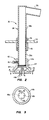
- Each nozzle 36 includes a vertical tubular portion 38 extending through a corresponding opening in the plate 24 and secured to the plate in any conventional manner such as by welding.
- the tubular portion 38 includes an externally threaded lower portion 38a projecting below the plate 24 for receiving air from the plenum 26, and an upper portion 38b extending above the plate and into the fluidized bed 22.
- the nozzle 36 also includes a discharge portion 38c registering with an opening formed through the upper end portion of the upper nozzle portion 38b.
- the discharge portion 38c extends downwardly at a slight angle to the horizontal. Thus, air travels upwardly through the nozzle portions 38a and 38b before entering the discharge portion 36c and discharging into the fluidized bed 22.
- An upper ring member 39 is secured to the upper nozzle portion 38b and rests against the upper surface of the plate 24 to locate the nozzle in the position shown.
- An internally threaded sleeve 40 extends just below the plate 24 and in threaded engagement with the threaded lower nozzle portion 38a. After the nozzle 36 is inserted through the opening in the plate 24, the sleeve 40 can be advanced upwardly on the lower nozzle portion 38a until it engages the lower surface of the plate 24 to secure the nozzle 36 in the position shown.
- a valve assembly 42 is connected to the lower end portion of the lower nozzle portion 38a.
- the assembly 42 includes a housing 44 having an upper cylindrical portion 44a and an enlarged hollow portion 44b extending from the cylindrical portion and defining a chamber 42c.
- a bolt 45 extends through an opening in the cylindrical portion 44a and in engagement with the lower nozzle portion 38a to secure the housing 44 to the nozzle 36.
- a disc valve 46 is disposed in the chamber 44c and four rods 48a, 48b, 48c and 48d extend from its lower surface.
- the rods 48a-48d extend through an opening 44d formed in the floor of the housing 44 and their respective free end portions are bent for approximately 900.
- the rods 48a-48d function to provide guiding support for the disc valve 46 as it moves within the chamber 44c to control the flow of air into the chamber and prevent the backflow of particulate material from the nozzle 36 through the opening 46d, as will be explained.
- the rods 48a-48d also function to limit the upper movement off the disc valve 46 by virtue of the bent portions thereof engaging the outer surface of the floor of the housing 44 in the upper position of the valve 46.
- the dampers 28 associated with the plenum 26 are opened and pressurized gas, such as air, passes through the duct 26a and the plenum and upwardly against the disc valves 46 of each of the nozzles 36. This forces the disc valves 46 upwardly and permits the air to enter the chamber 44c of each nozzle 36 via the opening 44d and pass into the end of the lower nozzle portion 38a.
- the air flows upwardly through the nozzle portions 38a and 38b and the discharge nozzle portion 38c before discharging into the bed 22 at a slightly downward discharge path above the plane of the plate 24.
- the air passes through the bed 22 (FIG. 1) to fluidize it and then passes, by convection, through the enclosure 10 in a generally upwardly directions.
- That portion of the particulate material in the bed 22 extending immediately above the nozzle portions 38c is fluidized and the portion extending between the latter portion and the upper surface of the plate 24 remains dormant, or stagnant.
- the nozzles 36 are oriented so that their horizontal discharge portions 38c are directed towards the rear wall 14. Although not clear from the drawing, it is understood that the discharge portions 38c can also be directed towards the drain pipe 34. As a result of this orientation, a momentum is imparted to the bed material which induces a circulation of the material to insure superior distribution, mixing and draining of the particulate material as discussed in detail in the aforementioned U.S. Patent.
- the light-off burner 32 and the burner in the duct 26a are then fired to heat the material in the bed until the temperature of the material reaches a predetermined level, and additional particulate fuel is discharged from the feeder 29 while adsorbent material is discharged onto the upper surface of the bed 22 as needed.
- the light-off burner 32 and the burner in the duct 26a are turned off while the feeder 29 continues to distribute particulate fuel to the upper surface of the bed in accordance with predetermined feed rates.
- Fluid, such as water, to be heated is passed into the headers 34a and 34b where it passes simultaneously, or in sequence, through the tubes 18 forming the walls 12, 14 and 16 to add heat from the fluidized bed to the fluid before it is passed to external apparatus for further processing.
- any bed material from the bed 22 tending to backflow through the nozzles 36 will force the disc valves 46 downwardly to a position where they cover their respective openings 44d and thus prevent further backflow of the particulate material into the plenum 26.
- valve assembly 42 can be connected to fluidization nozzles of a different configuration than that discussed above, and the number and specific locations of the nozzles and their specific orientation can be varied as long as the above objectives and results are achieved.
- the nozzles could be of one of the types disclosed in copending patent application serial number (attorney's docket no. 10283.301) assigned to the assignee of the present invention.
- the heat exchanger 10 can incorporate a circulating fluidized bed and the nozzle 36 and valve assembly 42 of the present invention can be used in other fluidized bed systems such as stripper coolers, J-valves, seal pots, etc.
- the valve assembly 42 of the present invention could be fabricated as an integral portion of the nozzle 36.
Landscapes
- Chemical & Material Sciences (AREA)
- Engineering & Computer Science (AREA)
- Combustion & Propulsion (AREA)
- Organic Chemistry (AREA)
- Chemical Kinetics & Catalysis (AREA)
- Mechanical Engineering (AREA)
- General Engineering & Computer Science (AREA)
- Fluidized-Bed Combustion And Resonant Combustion (AREA)
- Devices And Processes Conducted In The Presence Of Fluids And Solid Particles (AREA)
Applications Claiming Priority (2)
| Application Number | Priority Date | Filing Date | Title |
|---|---|---|---|
| US07/600,789 US5101576A (en) | 1990-10-22 | 1990-10-22 | Uni-directional fluidization nozzle and a fluidized bed system utilizing same |
| US600789 | 1990-10-22 |
Publications (1)
| Publication Number | Publication Date |
|---|---|
| EP0482799A1 true EP0482799A1 (fr) | 1992-04-29 |
Family
ID=24405047
Family Applications (1)
| Application Number | Title | Priority Date | Filing Date |
|---|---|---|---|
| EP91309322A Withdrawn EP0482799A1 (fr) | 1990-10-22 | 1991-10-10 | Buse de fluidisation unidirectionnelle et lit fluidifié utilisant celle-ci |
Country Status (6)
| Country | Link |
|---|---|
| US (1) | US5101576A (fr) |
| EP (1) | EP0482799A1 (fr) |
| JP (1) | JPH04260709A (fr) |
| CA (1) | CA2053437A1 (fr) |
| MX (1) | MX9101656A (fr) |
| PT (1) | PT99305A (fr) |
Cited By (3)
| Publication number | Priority date | Publication date | Assignee | Title |
|---|---|---|---|---|
| EP0567264A1 (fr) * | 1992-04-20 | 1993-10-27 | Foster Wheeler Energy Corporation | Système de lit fluidisé et tuyère pour la fluidification et le refroidissement de ce système |
| GB2271727A (en) * | 1992-10-26 | 1994-04-27 | Sumitomo Chemical Co | Gas distributor plate for fluidized bed reactors |
| WO1994019099A1 (fr) * | 1993-02-18 | 1994-09-01 | Hoechst Aktiengesellschaft | Dispositif d'oxychloration |
Families Citing this family (6)
| Publication number | Priority date | Publication date | Assignee | Title |
|---|---|---|---|---|
| US5395596A (en) * | 1993-05-11 | 1995-03-07 | Foster Wheeler Energy Corporation | Fluidized bed reactor and method utilizing refuse derived fuel |
| JPH0755112A (ja) * | 1993-08-16 | 1995-03-03 | Mitsubishi Heavy Ind Ltd | 流動化用空気ノズル |
| JP3085836B2 (ja) | 1993-11-29 | 2000-09-11 | 三菱重工業株式会社 | 流動化用空気噴射器 |
| US5806206A (en) * | 1997-08-22 | 1998-09-15 | Osram Sylvania Inc. | Gas distributor for vertical gas/solid reactors |
| US9333476B2 (en) * | 2014-07-16 | 2016-05-10 | Amec Foster Wheeler North America Corp. | Grid nozzle assembly, a fluidized bed reactor with a grid nozzle assembly and methods of using a grid nozzle assembly |
| CN105927970B (zh) * | 2016-05-30 | 2019-11-26 | 广东工业大学 | 具有均匀配风装置的循环流化床燃烧系统 |
Citations (1)
| Publication number | Priority date | Publication date | Assignee | Title |
|---|---|---|---|---|
| GB2148141A (en) * | 1983-10-14 | 1985-05-30 | Hydrocarbon Research Inc | Staged flow distribution grid assembly for ebullated bed reactor |
Family Cites Families (3)
| Publication number | Priority date | Publication date | Assignee | Title |
|---|---|---|---|---|
| CS162224B1 (fr) * | 1972-09-11 | 1975-07-15 | ||
| JPS5949413A (ja) * | 1982-09-13 | 1984-03-22 | Babcock Hitachi Kk | 流動層燃焼装置 |
| JPS6332280A (ja) * | 1986-07-23 | 1988-02-10 | 川崎重工業株式会社 | 流動層炉の気体分散装置 |
-
1990
- 1990-10-22 US US07/600,789 patent/US5101576A/en not_active Expired - Fee Related
-
1991
- 1991-10-10 EP EP91309322A patent/EP0482799A1/fr not_active Withdrawn
- 1991-10-15 CA CA002053437A patent/CA2053437A1/fr not_active Abandoned
- 1991-10-15 JP JP3266303A patent/JPH04260709A/ja active Pending
- 1991-10-18 MX MX9101656A patent/MX9101656A/es unknown
- 1991-10-22 PT PT99305A patent/PT99305A/pt not_active Application Discontinuation
Patent Citations (1)
| Publication number | Priority date | Publication date | Assignee | Title |
|---|---|---|---|---|
| GB2148141A (en) * | 1983-10-14 | 1985-05-30 | Hydrocarbon Research Inc | Staged flow distribution grid assembly for ebullated bed reactor |
Non-Patent Citations (1)
| Title |
|---|
| PATENT ABSTRACTS OF JAPAN vol. 10, no. 167 (M-488)(2223) 13 June 1986 & JP-A-61 017 809 ( BABCOCK HITACHI ) 25 January 1986 * |
Cited By (4)
| Publication number | Priority date | Publication date | Assignee | Title |
|---|---|---|---|---|
| EP0567264A1 (fr) * | 1992-04-20 | 1993-10-27 | Foster Wheeler Energy Corporation | Système de lit fluidisé et tuyère pour la fluidification et le refroidissement de ce système |
| GB2271727A (en) * | 1992-10-26 | 1994-04-27 | Sumitomo Chemical Co | Gas distributor plate for fluidized bed reactors |
| GB2271727B (en) * | 1992-10-26 | 1996-07-24 | Sumitomo Chemical Co | Gas distributor plate for fluidized bed reactors |
| WO1994019099A1 (fr) * | 1993-02-18 | 1994-09-01 | Hoechst Aktiengesellschaft | Dispositif d'oxychloration |
Also Published As
| Publication number | Publication date |
|---|---|
| MX9101656A (es) | 1992-06-05 |
| PT99305A (pt) | 1994-01-31 |
| CA2053437A1 (fr) | 1992-04-23 |
| US5101576A (en) | 1992-04-07 |
| JPH04260709A (ja) | 1992-09-16 |
Similar Documents
| Publication | Publication Date | Title |
|---|---|---|
| EP0567264B1 (fr) | Procédé de fluidification et tuyère pour la fluidification et le refroidissement | |
| US5239946A (en) | Fluidized bed reactor system and method having a heat exchanger | |
| EP0518482B1 (fr) | Système de combustion à lit fluidisé | |
| US4404755A (en) | Fluidized bed heat exchanger utilizing induced diffusion and circulation | |
| US5141708A (en) | Fluidized bed combustion system and method having an integrated recycle heat exchanger | |
| US5682828A (en) | Fluidized bed combustion system and a pressure seal valve utilized therein | |
| US4349969A (en) | Fluidized bed reactor utilizing zonal fluidization and anti-mounding pipes | |
| CA2041983C (fr) | Systeme de combustion en lit fluidise et methode faisant appel a un echangeur de chaleur a recyclage integral et a une chambre d'evacuation transversale | |
| CA2051995C (fr) | Systeme et methode de combustion en lit fluidise a echangeur de chaleur de recyclage muni d'un systeme de controle non mecanique des solides | |
| HK1001737B (en) | Fluidized bed combustion system | |
| EP0346062B1 (fr) | Réacteur à lit fluidisé utilisant des séparateurs en forme de canaux | |
| US4436507A (en) | Fluidized bed reactor utilizing zonal fluidization and anti-mounding air distributors | |
| CA2290978C (fr) | Reacteur a lit fluidise | |
| US5101576A (en) | Uni-directional fluidization nozzle and a fluidized bed system utilizing same | |
| US4359968A (en) | Fluidized bed heat exchanger utilizing a baffle system | |
| US4397102A (en) | Fluidized bed heat exchanger incorporating induced circulation utilizing directional and/or differential bed fluidization | |
| US5105559A (en) | Flow-seal fluidization nozzle and a fluidized bed system utilizing same | |
| US4521976A (en) | Method of operating a fluidized bed heat exchanger utilizing induced circulation | |
| US5286188A (en) | Uni-directional anti-backsifting fluidization nozzle and a fluidized bed system utilizing same | |
| US5735682A (en) | Fluidized bed combustion system having an improved loop seal valve | |
| US4446629A (en) | Fluidized bed heat exchanger utilizing induced circulation | |
| US5242662A (en) | Solids recycle seal system for a fluidized bed reactor | |
| EP0078706B1 (fr) | Echangeur de chaleur à lit fluidifié avec circulation induite utilisant une fluidification directionnelle et/ou différentielle | |
| EP0398718B1 (fr) | Système d'étanchéité appliqué au recyclage des matières solides dans un réacteur à lit fluidifié | |
| US5392736A (en) | Fludized bed combustion system and process for operating same |
Legal Events
| Date | Code | Title | Description |
|---|---|---|---|
| PUAI | Public reference made under article 153(3) epc to a published international application that has entered the european phase |
Free format text: ORIGINAL CODE: 0009012 |
|
| AK | Designated contracting states |
Kind code of ref document: A1 Designated state(s): ES GB IT |
|
| 17P | Request for examination filed |
Effective date: 19920818 |
|
| 17Q | First examination report despatched |
Effective date: 19940801 |
|
| STAA | Information on the status of an ep patent application or granted ep patent |
Free format text: STATUS: THE APPLICATION IS DEEMED TO BE WITHDRAWN |
|
| 18D | Application deemed to be withdrawn |
Effective date: 19950503 |