EP0483028A1 - Formen zur Herstellung von keramischen Gegenständen oder dergleichen durch Pressen - Google Patents
Formen zur Herstellung von keramischen Gegenständen oder dergleichen durch Pressen Download PDFInfo
- Publication number
- EP0483028A1 EP0483028A1 EP91420375A EP91420375A EP0483028A1 EP 0483028 A1 EP0483028 A1 EP 0483028A1 EP 91420375 A EP91420375 A EP 91420375A EP 91420375 A EP91420375 A EP 91420375A EP 0483028 A1 EP0483028 A1 EP 0483028A1
- Authority
- EP
- European Patent Office
- Prior art keywords
- pressing
- mold
- filling composition
- female
- male
- Prior art date
- Legal status (The legal status is an assumption and is not a legal conclusion. Google has not performed a legal analysis and makes no representation as to the accuracy of the status listed.)
- Granted
Links
- 238000003825 pressing Methods 0.000 title claims abstract description 59
- 239000000919 ceramic Substances 0.000 title claims abstract description 25
- 239000000203 mixture Substances 0.000 claims abstract description 43
- 238000004519 manufacturing process Methods 0.000 claims abstract description 29
- 239000011159 matrix material Substances 0.000 claims description 22
- 239000003795 chemical substances by application Substances 0.000 claims description 17
- 239000012530 fluid Substances 0.000 claims description 17
- 229910052500 inorganic mineral Inorganic materials 0.000 claims description 14
- 239000007788 liquid Substances 0.000 claims description 14
- 239000011707 mineral Substances 0.000 claims description 14
- 230000015572 biosynthetic process Effects 0.000 claims description 10
- 239000011575 calcium Substances 0.000 claims description 9
- 229910052791 calcium Inorganic materials 0.000 claims description 9
- 230000002787 reinforcement Effects 0.000 claims description 9
- 230000003014 reinforcing effect Effects 0.000 claims description 9
- 239000011505 plaster Substances 0.000 claims description 8
- OYPRJOBELJOOCE-UHFFFAOYSA-N Calcium Chemical compound [Ca] OYPRJOBELJOOCE-UHFFFAOYSA-N 0.000 claims description 7
- 239000002671 adjuvant Substances 0.000 claims description 5
- 229920000049 Carbon (fiber) Polymers 0.000 claims description 2
- 235000008733 Citrus aurantifolia Nutrition 0.000 claims description 2
- 235000011941 Tilia x europaea Nutrition 0.000 claims description 2
- ANBBXQWFNXMHLD-UHFFFAOYSA-N aluminum;sodium;oxygen(2-) Chemical compound [O-2].[O-2].[Na+].[Al+3] ANBBXQWFNXMHLD-UHFFFAOYSA-N 0.000 claims description 2
- -1 calcium aluminates Chemical class 0.000 claims description 2
- 239000004917 carbon fiber Substances 0.000 claims description 2
- 239000004568 cement Substances 0.000 claims description 2
- 239000003365 glass fiber Substances 0.000 claims description 2
- 239000004571 lime Substances 0.000 claims description 2
- 239000012764 mineral filler Substances 0.000 claims description 2
- 229910001388 sodium aluminate Inorganic materials 0.000 claims description 2
- 239000012209 synthetic fiber Substances 0.000 claims description 2
- 229920002994 synthetic fiber Polymers 0.000 claims description 2
- 229920003002 synthetic resin Polymers 0.000 claims description 2
- 239000000057 synthetic resin Substances 0.000 claims description 2
- 239000008346 aqueous phase Substances 0.000 claims 1
- 238000000034 method Methods 0.000 abstract description 24
- 238000005266 casting Methods 0.000 abstract description 3
- 230000003628 erosive effect Effects 0.000 description 15
- 239000000725 suspension Substances 0.000 description 11
- 238000007711 solidification Methods 0.000 description 9
- 230000008023 solidification Effects 0.000 description 9
- 230000007547 defect Effects 0.000 description 7
- 239000000463 material Substances 0.000 description 7
- 229910052751 metal Inorganic materials 0.000 description 7
- 239000002184 metal Substances 0.000 description 7
- 239000004033 plastic Substances 0.000 description 7
- XLYOFNOQVPJJNP-UHFFFAOYSA-N water Substances O XLYOFNOQVPJJNP-UHFFFAOYSA-N 0.000 description 7
- 238000000465 moulding Methods 0.000 description 6
- 239000007900 aqueous suspension Substances 0.000 description 5
- 230000003068 static effect Effects 0.000 description 4
- 238000010438 heat treatment Methods 0.000 description 3
- 238000009776 industrial production Methods 0.000 description 3
- 150000004645 aluminates Chemical class 0.000 description 2
- 238000007664 blowing Methods 0.000 description 2
- 239000004927 clay Substances 0.000 description 2
- 230000006866 deterioration Effects 0.000 description 2
- 229910052571 earthenware Inorganic materials 0.000 description 2
- 238000002347 injection Methods 0.000 description 2
- 239000007924 injection Substances 0.000 description 2
- 238000002360 preparation method Methods 0.000 description 2
- 238000011282 treatment Methods 0.000 description 2
- DGAQECJNVWCQMB-PUAWFVPOSA-M Ilexoside XXIX Chemical compound C[C@@H]1CC[C@@]2(CC[C@@]3(C(=CC[C@H]4[C@]3(CC[C@@H]5[C@@]4(CC[C@@H](C5(C)C)OS(=O)(=O)[O-])C)C)[C@@H]2[C@]1(C)O)C)C(=O)O[C@H]6[C@@H]([C@H]([C@@H]([C@H](O6)CO)O)O)O.[Na+] DGAQECJNVWCQMB-PUAWFVPOSA-M 0.000 description 1
- 239000004952 Polyamide Substances 0.000 description 1
- 241001080024 Telles Species 0.000 description 1
- 240000008042 Zea mays Species 0.000 description 1
- 230000009286 beneficial effect Effects 0.000 description 1
- 230000005540 biological transmission Effects 0.000 description 1
- 125000004122 cyclic group Chemical group 0.000 description 1
- 239000006185 dispersion Substances 0.000 description 1
- 239000000835 fiber Substances 0.000 description 1
- 238000002156 mixing Methods 0.000 description 1
- 238000004421 molding of ceramic Methods 0.000 description 1
- 229920002647 polyamide Polymers 0.000 description 1
- 229920000728 polyester Polymers 0.000 description 1
- 229920000098 polyolefin Polymers 0.000 description 1
- 238000004321 preservation Methods 0.000 description 1
- 229920005989 resin Polymers 0.000 description 1
- 239000011347 resin Substances 0.000 description 1
- 238000007493 shaping process Methods 0.000 description 1
- 230000035939 shock Effects 0.000 description 1
- 239000011734 sodium Substances 0.000 description 1
- 229910052708 sodium Inorganic materials 0.000 description 1
Images

Classifications
-
- C—CHEMISTRY; METALLURGY
- C04—CEMENTS; CONCRETE; ARTIFICIAL STONE; CERAMICS; REFRACTORIES
- C04B—LIME, MAGNESIA; SLAG; CEMENTS; COMPOSITIONS THEREOF, e.g. MORTARS, CONCRETE OR LIKE BUILDING MATERIALS; ARTIFICIAL STONE; CERAMICS; REFRACTORIES; TREATMENT OF NATURAL STONE
- C04B22/00—Use of inorganic materials as active ingredients for mortars, concrete or artificial stone, e.g. accelerators or shrinkage compensating agents
- C04B22/0093—Aluminates
-
- B—PERFORMING OPERATIONS; TRANSPORTING
- B28—WORKING CEMENT, CLAY, OR STONE
- B28B—SHAPING CLAY OR OTHER CERAMIC COMPOSITIONS; SHAPING SLAG; SHAPING MIXTURES CONTAINING CEMENTITIOUS MATERIAL, e.g. PLASTER
- B28B7/00—Moulds; Cores; Mandrels
- B28B7/0097—Press moulds; Press-mould and press-ram assemblies
-
- B—PERFORMING OPERATIONS; TRANSPORTING
- B28—WORKING CEMENT, CLAY, OR STONE
- B28B—SHAPING CLAY OR OTHER CERAMIC COMPOSITIONS; SHAPING SLAG; SHAPING MIXTURES CONTAINING CEMENTITIOUS MATERIAL, e.g. PLASTER
- B28B7/00—Moulds; Cores; Mandrels
- B28B7/34—Moulds, cores, or mandrels of special material, e.g. destructible materials
- B28B7/344—Moulds, cores, or mandrels of special material, e.g. destructible materials from absorbent or liquid- or gas-permeable materials, e.g. plaster moulds in general
-
- B—PERFORMING OPERATIONS; TRANSPORTING
- B28—WORKING CEMENT, CLAY, OR STONE
- B28B—SHAPING CLAY OR OTHER CERAMIC COMPOSITIONS; SHAPING SLAG; SHAPING MIXTURES CONTAINING CEMENTITIOUS MATERIAL, e.g. PLASTER
- B28B7/00—Moulds; Cores; Mandrels
- B28B7/34—Moulds, cores, or mandrels of special material, e.g. destructible materials
- B28B7/346—Manufacture of moulds
-
- C—CHEMISTRY; METALLURGY
- C04—CEMENTS; CONCRETE; ARTIFICIAL STONE; CERAMICS; REFRACTORIES
- C04B—LIME, MAGNESIA; SLAG; CEMENTS; COMPOSITIONS THEREOF, e.g. MORTARS, CONCRETE OR LIKE BUILDING MATERIALS; ARTIFICIAL STONE; CERAMICS; REFRACTORIES; TREATMENT OF NATURAL STONE
- C04B28/00—Compositions of mortars, concrete or artificial stone, containing inorganic binders or the reaction product of an inorganic and an organic binder, e.g. polycarboxylate cements
- C04B28/14—Compositions of mortars, concrete or artificial stone, containing inorganic binders or the reaction product of an inorganic and an organic binder, e.g. polycarboxylate cements containing calcium sulfate cements
-
- C—CHEMISTRY; METALLURGY
- C04—CEMENTS; CONCRETE; ARTIFICIAL STONE; CERAMICS; REFRACTORIES
- C04B—LIME, MAGNESIA; SLAG; CEMENTS; COMPOSITIONS THEREOF, e.g. MORTARS, CONCRETE OR LIKE BUILDING MATERIALS; ARTIFICIAL STONE; CERAMICS; REFRACTORIES; TREATMENT OF NATURAL STONE
- C04B2111/00—Mortars, concrete or artificial stone or mixtures to prepare them, characterised by specific function, property or use
- C04B2111/00474—Uses not provided for elsewhere in C04B2111/00
- C04B2111/00939—Uses not provided for elsewhere in C04B2111/00 for the fabrication of moulds or cores
Definitions
- the invention relates to molds by the formation by pressing of ceramic or similar objects, molds comprising two parts, one male and the other female.
- the invention also relates to the method of manufacturing said molds.
- the invention also relates to the compositions used for the production of the molds.
- the invention relates to ceramic objects shaped by pressing by applying said molds to their shaping.
- the molds intended for the formation of ceramic objects, according to the pressing process are produced, for example, by means of a mixture of resins and sands, or even and more generally by mixing special plasters, called "plasters of molding".
- the mineral materials constituting the molds are chosen for their capacity to create, during their implementation, capillary or microporous structures allowing the circulation of liquid and / or gaseous fluids, such as water coming from the ceramic paste used for the forming by pressing the desired object, and the air injected into the mold to take off the molded part after pressing.
- the mold used is formed of two parts, one male and the other female, constituting the imprints of said mold.
- One of the parts, whether male or female, is generally static, while the other is mobile, both causing, by the action of an appropriate effort, the creation of the desired object by deformation of a volume of plastic ceramic paste between the two imprints.
- the female part of the mold is subjected to multiple repeated mechanical stresses, which are the cause of rapid and significant deterioration, leading to the often often early reform of the mold.
- the female part of the mold is obtained by filling a metal frame by means, for example, an aqueous suspension of molding plaster, possibly associated with certain adjuvants, the chassis being previously provided with a matrix capable of creating the desired imprint, by means of reinforcement such as reinforcements and means allowing the subsequent circulation of liquid and / or gaseous fluids in the structure of the mold.
- a first object of the invention aims to produce molds for pressing, the female part of which is no longer the seat of anarchic ruptures and thus to avoid the appearance of early deterioration of the mold imprints.
- Another object of the invention is to produce molds for pressing having an improved capacity to resist the erosion of the walls of the imprints during the dynamic deformation of the plastic ceramic pastes during pressing.
- a final object of the invention aims to create molds with a surely improved lifetime, performing in industrial production at least twice as many pressing operations as with molds of known art.
- face of at least one of the parts of a mold will define all or a fraction of any of the walls or the bottom of at least one of the male or female parts of said mold.
- the molds for the formation of ceramic objects by pressing consisting of two parts, one male and the other female, are characterized in that at least one of the faces of at least one of the parts is dissociated from the other faces.
- Figure 1 shows in vertical section, the embodiment of the female part of a mold of the prior art for the formation of ceramic objects by pressing.
- Figure 2 shows in vertical section, the mold of Figure 1 after its production and its industrial implementation according to the pressing process, in which the female part is static and the male part, mobile.
- Figure 3 shows in horizontal section along J, J ′ the mold of Figure 1 after its production and industrial implementation according to the pressing process.
- a matrix (1) treated with a release agent and a metal reinforcement frame (2) are first placed in position on a horizontal support (3), the surface of which has was also treated by a release agent. Then having placed, in accordance with the techniques of the trade, reinforcing means and means allowing the subsequent circulation of liquid fluids (water) and / or gaseous, the free zone between the matrix (1) and the chassis (2) is filled in a single operation to the upper face (4) of the frame (2) by means of an aqueous suspension of a molding plaster (5).
- the aqueous filling suspension has solidified and an air circulation has been practiced to create the desired internal porosity, the frame (2) and its filling (5) are removed from the support (3) and constitute the female part. a pressing mold.
- the pressing mold comprising the female part of the frame (2), its porous filling (5) and the male part (7)
- a volume of ceramic paste plastic (6) is placed in the bottom, then subjected to a dynamic deformation by pressing by means of the male part of the mold moving in the direction of the arrow (8) until the formation of the desired object. Therefore, the male part (7) rises by driving the formed object, the injection of compressed air into the parts (5) and (7) of the mold at appropriate times allowing easy removal of the object obtained.
- the mold according to the invention differs from the known art in that at least one of the faces of at least one of the male and / or female parts constituting said mold is separated from the other faces.
- the part of which at least one of the faces is separated from the other faces is no longer monoblock but multiblock and therefore opposes mechanical stresses, causing early ruptures and deep erosions, sufficient elasticity d 'a constraint zone to another zone to allow it to absorb these constraints without the appearance of the early damage previously noted.
- the pressing molds, object of the invention can be made of materials as diverse as molding plasters, associated or not with known adjuvants, in the form of aqueous suspensions, or also synthetic resins possibly containing mineral fillers, all these materials having the property of acquiring or providing sufficient microporosity to allow the circulation of liquid and / or gaseous fluids in the mass of said mold.
- the molds according to the invention are produced by means of an inorganic filling composition based on at least one of plasters of known type usually used for the production of pressing molds, this composition comprising, expressed in percent by weight of dry matter:
- the plaster for molding can be chosen from the products marketed for this purpose, such as for example PRESTIAFORM marketed by PRESTIA LAFARGE, MOLDA PRESSAGE marketed by LAMBERT, KERADUR marketed by BOERGARDTS, ASDUR marketed by GIULINI, or others.
- the implementation of the aforementioned mineral composition is carried out starting from a dispersion of an appropriate weight quantity of said composition represented by (P) expressed in parts by weight in a unit volume of water represented by (E) also expressed in parts by weight leading to the definition of a P / E ratio.
- the P / E ratio is chosen in the range 2.5 / 1 to 3.2 / 1.
- compositions can also be introduced into the abovementioned compositions, these various adjuvants being, for example, glass fibers, carbon fibers, synthetic fibers, such as polyolefin fibers, polyamides, polyesters, polyacrylics.
- these various adjuvants being, for example, glass fibers, carbon fibers, synthetic fibers, such as polyolefin fibers, polyamides, polyesters, polyacrylics.
- the filling composition is introduced into said free zone, which, during and after solidification, undergoes the treatments usually practiced by those skilled in the art, to create the desired porosity, that is to say, the introduction of compressed air and possibly a heat treatment.
- the screen placed at the limit of the faces to be separated is removed, possibly placed in a new position, the surface thus freed from the solidified filling composition is treated with a release agent.
- this free zone zone (delimited by the matrix, the surfaces cleared of their screen, and the screen in its new position) means allowing the subsequent circulation of liquid and / or gaseous fluids which can be connected by means sealed to those of the first zone or left independent and then the composition of filling, which during and after solidification, undergoes as in the first step, the treatments usually practiced by those skilled in the art, such as introduction of compressed air, heat treatment and others.
- the parts of the mold according to the invention have as many separate faces as it is desirable to have.
- each zone of the part of the mold, the faces of which must be separated is produced individually by means of two separate molds, then after setting, the latter are mounted, possibly adjusted in the presence of a flexible seal.
- the molds for pressing according to the invention comprising male and female parts, owing to the fact that at least one of the faces of at least one of the parts is separated from the other faces, offer exceptional longevity when they are used on an industrial scale, having a lifespan of at least twice that of the previous pressing molds which are the seat of almost immediate ruptures.
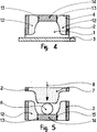
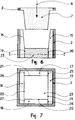
- Figures 4 to 7 illustrate an embodiment of the female part of the mold according to the invention ( Figure 4) according to the step process comprising at least two separate sides ( Figures 4, 6, 7) and the exploitation of the mold in industrial production ( Figures 5 and 6).
- FIG. 4 represents, in vertical section, an embodiment of the female part of a mold according to the invention.
- Figure 5 shows, in vertical section, the female parts (of Figure 4) and male constituting the mold according to the invention during their industrial implementation according to the pressing process.
- Figure 6 shows a vertical section of a pressing mold according to the invention, the female part of which has eight separate faces.
- Figure 7 shows a horizontal section of Figure 6 made along I, I 'to observe the eight sides separated from the female part of the mold according to the invention.
- a matrix (4) and a metal reinforcing frame (2) are placed on a horizontal support (3), matrix and plate being previously treated by a release agent.
- a screen (13) is placed vertically at the limit of the faces which it is desirable to separate. Therefore and according to techniques known in the art, reinforcing means (not shown) and means allowing the subsequent circulation of liquid fluids (water) and / or gaseous fluids (air) (not shown), are placed in the free area (12) delimited by the chassis (2), part of the matrix (1) and the screen (13). This area is then filled up to the upper face (4) of the frame (2) by means of an aqueous suspension of a plaster conforming to the above-mentioned compositions. During the solidification of said suspension, air was blown in order to create the desired internal porosity, using the circulation means (fluids) located in this zone (12).
- the screen (13) is removed and the surface of the filling material thus discovered is treated with a release agent.
- the free zone (14) delimited by the part of the matrix not yet used and the surface of the filling material of the zone (12) freed from the screen (13), is provided with means for reinforcement (not shown) and means allowing the subsequent circulation of liquid (water) and / or gaseous (air) fluids (not shown), the latter being able to be connected in a sealed manner to those of the zone (12) or kept independent.
- the free zone (14) is then filled up to the upper face of the frame (2) by means of an aqueous plaster suspension of composition identical to that used in the zone (12).
- an air blowing using the means of circulation of the fluids is practiced to create the desired internal porosity.
- Figure 5 which is a vertical section of the female (according to Figure 4) and male parts constituting the mold according to the invention, illustrates the industrial implementation of said mold according to a pressing process.
- a volume of plastic ceramic paste (6) is placed in the bottom of the female part, then is subjected to a dynamic deformation by pressing by means of the male part (7) of the mold moving in the direction of the arrow (8) until the desired object is formed.
- the male part (7) of the mold rises, driving the formed object, while at the same time, compressed air is injected into the male and female parts of the mold, at appropriate times to allow easy demolding of said mold. object.
- the repetition of the pressing cycle does not cause any rupture of the female part of the mold, no defect on the molded objects.
- Figures 6 and 7 illustrate the case of a mold according to the invention, one of the parts (the female part) has eight separate faces.
- FIG. 6 is a vertical section of the male (7) and female parts constituting the mold according to the invention used in a pressing process, the female part is produced according to the method in successive stages, in accordance with the description which is given in the case of FIG. 4.
- Figure 7 which is a section of Figure 6 along I, I 'allows to see in the female part of the mold according to the invention, all the faces of the filling zones (15, 16, 17, 18 and 23) separated each other (19, 20, 21, 22, 24, 25, 26 and 27), produced in successive stages in accordance with the method described in the case of Figure 4.
- This example illustrates the production and the industrial implementation of a pressing mold according to the prior art for the manufacture of a container (hollow oval dish) having the dimensions 270 mm x 180 mm x 75 mm.
- This mold in accordance with Figures 1 and 2, has two parts, one female (static) and the other male (mobile).
- a matrix (1) embssed
- the metal reinforcing frame (2) containing it are placed on the horizontal support (3), the surfaces of the matrix and of the plate being treated with an agent. mold release.
- a porous sheath around the matrix as well as reinforcing means are placed in accordance with techniques known to those skilled in the art. Then the free area between the matrix (1) and the metal frame (2) is filled in a single operation by means of an aqueous mineral suspension having the following composition:
- the male part of the mold is produced according to the same principle, the free zone left by the hollow matrix being filled with an aqueous mineral suspension having the following composition:
- the male part undergoes an injection of air until the desired porosity is obtained. Said male part thus produced is in one piece.
- the two male and female parts of the mold thus prepared were mounted on a hydraulic press of the VICENTINI type, having a power of 20 tonnes on the piston.
- the ceramic paste used for pressing the object is of the earthenware type (clay-based) with a water content of 20 percent.
- the female part of the mold underwent a first rupture (according to item 9 in Figure 2) from the tenth part produced, causing other breaks according to the items (30) and (31) of the Figure 3.
- the mold was able to produce pressed parts, but having raised marks corresponding to the rupture slots.
- the female and male parts revealed, from around the hundredth piece, an erosion which became more pronounced over time. The combination of these various defects caused the reform of the mold after approximately 1,500 parts produced.
- This example illustrates the production and the industrial implementation of a pressing mold according to the invention for the manufacture of the same container as that of Example 1.
- This mold in accordance with Figures 4 and 5, has two parts, one female (static) and the other male (mobile).
- the matrix (1) and the metal reinforcement frame (2) are placed on the horizontal support (3), the surfaces of the matrix and of the plate being previously treated with a release agent. .
- a screen (13) is placed vertically according to the position indicated in Figure 4, at the limit of the faces that it is desirable to separate.
- the reinforcing means and means for the circulation of fluids (porous sheath) liquid and / or gaseous are placed in the free zone (12). This area is then filled up to the upper face (4) of the frame (2) by means of an aqueous mineral suspension having the following composition:
- a forced air circulation is practiced through the porous sheath until obtaining an internal porosity as desired.
- the screen (13) is removed and the surface of the filling material thus discovered is treated with a release agent.
- the free zone (14) delimited by the part of the matrix not yet used and the surface of the filling material of the zone (12) freed from the screen (13), is provided with means for reinforcement and means for circulation of liquid and / or gaseous fluids (porous sheath), the latter being tightly connected to the porous sheath placed in zone 12.
- the free zone (14) is then filled up to the upper face (4) of the frame (2) by means of the same aqueous suspension as that implementation in area (12).
- the male part of the mold was produced according to the one-piece principle as described in Example 1, the free zone left by the hollow matrix being filled with an aqueous mineral suspension having the following composition:
- this male part undergoes an insufflation of air until the desired porosity is obtained.
- the two male and female parts of the mold were mounted on the VICENTINI hydraulic press with a power of 20 tonnes on the piston.
- the ceramic paste used for pressing the object is of the earthenware type (clay-based), with a water content of 20 percent by weight.
- This example illustrates the production and the industrial implementation of a pressing mold according to the invention for the manufacture of the same container as that of Examples 1 and 2.
- the mold conforms to Figures 4 and 5.
- the male and female parts are produced according to the principles described in Example 2, the female part being multi-block, the male part, monobloc.
- the mold differs from that of Example 2 by the composition of the aqueous mineral suspensions used for its production.
- the aqueous mineral suspension for filling has the following composition:
- the aqueous mineral suspension for filling has the following composition:
- the two male and female parts are mounted on the VICENTINI hydraulic press with a power of 20 tonnes on the piston.
- the ceramic paste used for pressing the object is the same as that of Examples 1 and 2.
- the female part of the mold was not broken.
- the mold was able to produce approximately 4,000 pieces without fault. From this number, the male and female parts began to show the beginning of erosion, a phenomenon which increased according to the number of parts produced.
- the mold was reformed only at about 7,500 parts produced, due to the only erosion observed, equivalent to that observed in Example 1 at the time of the reform of the mold, the parts produced however not having major fault.
- This example illustrates the production and the industrial implementation of a pressing mold according to the invention for the manufacture of a cubic container of dimensions 120 mm ⁇ 120 mm ⁇ 120 mm.
- the male and female parts are produced according to the principles described in Example 2, the male part being monobloc and the female part multiblock.
- the female part was carried out in five successive stages to create the zones (15, 16, 17, 18 and 23), whose faces (19, 20, 21, 22, 24, 25, 26 and 27) are, of this way, all separated.
- the means allowing the circulation of liquid and / or gaseous fluids (porous sheath) in each of the aforementioned zones are connected to those of the other zones by sealed means.
- compositions of the aqueous mineral suspensions used for the production of the male and female parts are those described in Example 3.
- the male and female parts are mounted on the VICENTINI hydraulic press with a power of 20 tonnes on the piston.
- the ceramic paste used is identical to that of the other examples.
Landscapes
- Chemical & Material Sciences (AREA)
- Engineering & Computer Science (AREA)
- Ceramic Engineering (AREA)
- Mechanical Engineering (AREA)
- Manufacturing & Machinery (AREA)
- Organic Chemistry (AREA)
- Structural Engineering (AREA)
- Materials Engineering (AREA)
- Inorganic Chemistry (AREA)
- Chemical Kinetics & Catalysis (AREA)
- Press-Shaping Or Shaping Using Conveyers (AREA)
- Devices For Post-Treatments, Processing, Supply, Discharge, And Other Processes (AREA)
- Compositions Of Oxide Ceramics (AREA)
- Ceramic Products (AREA)
Applications Claiming Priority (2)
| Application Number | Priority Date | Filing Date | Title |
|---|---|---|---|
| FR9013341A FR2668093A1 (fr) | 1990-10-23 | 1990-10-23 | Moules pour la formation par pressage d'objets ceramiques ou analogues. |
| FR9013341 | 1990-10-23 |
Publications (2)
| Publication Number | Publication Date |
|---|---|
| EP0483028A1 true EP0483028A1 (de) | 1992-04-29 |
| EP0483028B1 EP0483028B1 (de) | 1996-02-21 |
Family
ID=9401629
Family Applications (1)
| Application Number | Title | Priority Date | Filing Date |
|---|---|---|---|
| EP91420375A Expired - Lifetime EP0483028B1 (de) | 1990-10-23 | 1991-10-22 | Formen zur Herstellung von keramischen Gegenständen oder dergleichen durch Pressen |
Country Status (7)
| Country | Link |
|---|---|
| EP (1) | EP0483028B1 (de) |
| AT (1) | ATE134330T1 (de) |
| DE (2) | DE69117247D1 (de) |
| ES (1) | ES2032718T1 (de) |
| FR (1) | FR2668093A1 (de) |
| GR (1) | GR920300072T1 (de) |
| PT (1) | PT99312B (de) |
Cited By (6)
| Publication number | Priority date | Publication date | Assignee | Title |
|---|---|---|---|---|
| ES2120864A1 (es) * | 1995-06-26 | 1998-11-01 | Jueguetes Oliver S A | Molde para conformar figuras de barro. |
| CN116568469A (zh) * | 2020-11-27 | 2023-08-08 | 乐尔幸华奥斯株式会社 | 印网掩模、图案模具、人造大理石的制造方法及人造大理石 |
| US12459292B2 (en) | 2020-11-27 | 2025-11-04 | Lx Hausys, Ltd. | Artificial marble including opaque striped region and transparent base region |
| US12459872B2 (en) | 2020-11-27 | 2025-11-04 | Lx Hausys, Ltd. | Artificial marble including stripes having high light transmittance |
| US12479765B2 (en) | 2020-11-27 | 2025-11-25 | Lx Hausys, Ltd. | Artificial marble having high light transmittance |
| US12509397B2 (en) | 2020-11-27 | 2025-12-30 | Lx Hausys, Ltd. | Artificial marble having high light transmittance |
Families Citing this family (1)
| Publication number | Priority date | Publication date | Assignee | Title |
|---|---|---|---|---|
| CN112720800B (zh) * | 2020-12-16 | 2022-07-26 | 佛山市恒力泰机械有限公司 | 一种耐火匣子的压制成型方法、设备及耐火匣子 |
Citations (7)
| Publication number | Priority date | Publication date | Assignee | Title |
|---|---|---|---|---|
| US2248032A (en) * | 1938-02-22 | 1941-07-01 | Ici Ltd | Manufacture of cements from calcium sulphate and blast furnace slag |
| US2400905A (en) * | 1943-10-15 | 1946-05-28 | Antioch College | Expansion control of molds and the like |
| GB962826A (en) * | 1961-11-07 | 1964-07-01 | Reginald Cotterell Butler | Refractory binding materials and refractory moulds made therefrom |
| FR2227937A1 (de) * | 1973-05-03 | 1974-11-29 | Schwarzheide Synthesewerk Veb | |
| DE2403835B1 (de) * | 1974-01-28 | 1975-03-13 | Keraplast Hans Handke Kg, 8595 Waldsassen | Arbeitsform zum Herstellen lederharter keramischer Formlinge |
| US3993727A (en) * | 1974-12-18 | 1976-11-23 | Wallace-Murray Corporation | Fluid-release mold and the method of manufacturing the same |
| DE3644144A1 (de) * | 1986-12-23 | 1988-07-07 | Kober Heide | Presswerkzeug |
-
1990
- 1990-10-23 FR FR9013341A patent/FR2668093A1/fr active Granted
-
1991
- 1991-10-22 DE DE69117247T patent/DE69117247D1/de not_active Expired - Lifetime
- 1991-10-22 AT AT91420375T patent/ATE134330T1/de not_active IP Right Cessation
- 1991-10-22 ES ES199191420375T patent/ES2032718T1/es active Pending
- 1991-10-22 DE DE199191420375T patent/DE483028T1/de active Pending
- 1991-10-22 EP EP91420375A patent/EP0483028B1/de not_active Expired - Lifetime
- 1991-10-23 PT PT99312A patent/PT99312B/pt not_active IP Right Cessation
-
1992
- 1992-12-30 GR GR92300072T patent/GR920300072T1/el unknown
Patent Citations (7)
| Publication number | Priority date | Publication date | Assignee | Title |
|---|---|---|---|---|
| US2248032A (en) * | 1938-02-22 | 1941-07-01 | Ici Ltd | Manufacture of cements from calcium sulphate and blast furnace slag |
| US2400905A (en) * | 1943-10-15 | 1946-05-28 | Antioch College | Expansion control of molds and the like |
| GB962826A (en) * | 1961-11-07 | 1964-07-01 | Reginald Cotterell Butler | Refractory binding materials and refractory moulds made therefrom |
| FR2227937A1 (de) * | 1973-05-03 | 1974-11-29 | Schwarzheide Synthesewerk Veb | |
| DE2403835B1 (de) * | 1974-01-28 | 1975-03-13 | Keraplast Hans Handke Kg, 8595 Waldsassen | Arbeitsform zum Herstellen lederharter keramischer Formlinge |
| US3993727A (en) * | 1974-12-18 | 1976-11-23 | Wallace-Murray Corporation | Fluid-release mold and the method of manufacturing the same |
| DE3644144A1 (de) * | 1986-12-23 | 1988-07-07 | Kober Heide | Presswerkzeug |
Non-Patent Citations (3)
| Title |
|---|
| CHEMICAL ABSTRACTS, vol. 109, no. 8, Août 1988, Columbus, Ohio, US; abstract no. 60359, V.F. CHERNYKH: 'PROPERTIES OF PLASTER OF PARIS CONTAINING A SUPERPLASTICIZER' page 361 ; * |
| CHEMICAL ABSTRACTS, vol. 94, no. 24, 15 Juin 1981, Columbus, Ohio, US; abstract no. 196566, M. V. PULIN: 'PROPERTIES OF MIXTURES OF GYPSUM SEMIHYDRATE WITH ALUMINA CEMENT' page 284 ; * |
| SYNDICAT NATIONAL DES INDUSTRIES DU PLATRE LE PLATRE PHISICO-CHIMIE FABRICATION ET EMPLOIS 1982,EDITIONS EYROLLES,PARIS,P.238-240 * |
Cited By (6)
| Publication number | Priority date | Publication date | Assignee | Title |
|---|---|---|---|---|
| ES2120864A1 (es) * | 1995-06-26 | 1998-11-01 | Jueguetes Oliver S A | Molde para conformar figuras de barro. |
| CN116568469A (zh) * | 2020-11-27 | 2023-08-08 | 乐尔幸华奥斯株式会社 | 印网掩模、图案模具、人造大理石的制造方法及人造大理石 |
| US12459292B2 (en) | 2020-11-27 | 2025-11-04 | Lx Hausys, Ltd. | Artificial marble including opaque striped region and transparent base region |
| US12459872B2 (en) | 2020-11-27 | 2025-11-04 | Lx Hausys, Ltd. | Artificial marble including stripes having high light transmittance |
| US12479765B2 (en) | 2020-11-27 | 2025-11-25 | Lx Hausys, Ltd. | Artificial marble having high light transmittance |
| US12509397B2 (en) | 2020-11-27 | 2025-12-30 | Lx Hausys, Ltd. | Artificial marble having high light transmittance |
Also Published As
| Publication number | Publication date |
|---|---|
| EP0483028B1 (de) | 1996-02-21 |
| ES2032718T1 (es) | 1993-03-01 |
| ATE134330T1 (de) | 1996-03-15 |
| PT99312A (pt) | 1994-02-28 |
| DE69117247D1 (de) | 1996-03-28 |
| FR2668093A1 (fr) | 1992-04-24 |
| GR920300072T1 (en) | 1992-12-30 |
| PT99312B (pt) | 1999-04-30 |
| FR2668093B1 (de) | 1997-02-07 |
| DE483028T1 (de) | 1992-11-05 |
Similar Documents
| Publication | Publication Date | Title |
|---|---|---|
| CH618361A5 (de) | ||
| EP0483028B1 (de) | Formen zur Herstellung von keramischen Gegenständen oder dergleichen durch Pressen | |
| US3431332A (en) | Ceramic casting techniques | |
| US7727429B2 (en) | Core for molding a ceramic discharge vessel | |
| KR20110057194A (ko) | 블록 몰드 및 방법 | |
| JPH09253792A (ja) | 鋳造用紙中子およびその製造方法 | |
| JPH0623505A (ja) | ダイカスト鋳造用崩壊性置中子 | |
| JP4117514B2 (ja) | 鋳型 | |
| FR2613659A1 (fr) | Procede de fabrication de pieces rigides et creuses presentant ou non des contre depouilles | |
| CA2312205C (fr) | Moule pour la fabrication d'un stick | |
| US20200180014A1 (en) | System and Method for Complex Objects Molding | |
| EP0459486A2 (de) | Modell zur Herstellung von Kokillen | |
| JPH02501660A (ja) | 膨張性の及び膨張したプラスチック材料組成物ならびにこのような膨張した組成物を成型形体で使用する金属鋳造物の鋳造法 | |
| FR2668094A1 (fr) | Compositions minerales pour moules de pressage, calibrage ou coulage. | |
| EP1004417B1 (de) | Verfahren zur Herstellung von Formwerkzeugen mit auswechselbarer Schale durch Transfer-Spritzen von Harz (RTM-Verfahren) | |
| JP2005088497A (ja) | 鋳込み成形方法 | |
| US4526220A (en) | Method for improving performance of chaplets in metal casting | |
| JPS63130257A (ja) | 浸漬ノズルの製造方法 | |
| FR2876687A1 (fr) | Procede de garnissage de recipient avec une masse microporeuse | |
| JP2518573B2 (ja) | 鋳込成形型 | |
| JPH01269505A (ja) | 有底成形体の鋳込成形方法及び成形鋳込型 | |
| JPH071080A (ja) | 成形用特殊中子 | |
| CN204353431U (zh) | 一种引导轮芯子模具 | |
| FR2636559A1 (fr) | Procede de coulee en barbotine de pieces en ceramique comportant des cavites | |
| JP2025143708A (ja) | アルミニウム鋳物の製造方法及び中空シェル |
Legal Events
| Date | Code | Title | Description |
|---|---|---|---|
| PUAI | Public reference made under article 153(3) epc to a published international application that has entered the european phase |
Free format text: ORIGINAL CODE: 0009012 |
|
| AK | Designated contracting states |
Kind code of ref document: A1 Designated state(s): AT BE CH DE DK ES FR GB GR IT LI LU NL SE |
|
| 17P | Request for examination filed |
Effective date: 19920512 |
|
| ITCL | It: translation for ep claims filed |
Representative=s name: STUDIO TORTA SOCIETA' SEMPLICE |
|
| GBC | Gb: translation of claims filed (gb section 78(7)/1977) | ||
| TCAT | At: translation of patent claims filed | ||
| TCNL | Nl: translation of patent claims filed | ||
| DET | De: translation of patent claims | ||
| REG | Reference to a national code |
Ref country code: ES Ref legal event code: BA2A Ref document number: 2032718 Country of ref document: ES Kind code of ref document: T1 |
|
| 17Q | First examination report despatched |
Effective date: 19930611 |
|
| RAP1 | Party data changed (applicant data changed or rights of an application transferred) |
Owner name: PRESTIA LAFARGE |
|
| GRAA | (expected) grant |
Free format text: ORIGINAL CODE: 0009210 |
|
| RAP1 | Party data changed (applicant data changed or rights of an application transferred) |
Owner name: LAFARGE PRESTIA |
|
| AK | Designated contracting states |
Kind code of ref document: B1 Designated state(s): AT BE CH DE DK ES FR GB GR IT LI LU NL SE |
|
| PG25 | Lapsed in a contracting state [announced via postgrant information from national office to epo] |
Ref country code: NL Free format text: LAPSE BECAUSE OF FAILURE TO SUBMIT A TRANSLATION OF THE DESCRIPTION OR TO PAY THE FEE WITHIN THE PRESCRIBED TIME-LIMIT Effective date: 19960221 Ref country code: GR Free format text: LAPSE BECAUSE OF FAILURE TO SUBMIT A TRANSLATION OF THE DESCRIPTION OR TO PAY THE FEE WITHIN THE PRESCRIBED TIME-LIMIT Effective date: 19960221 Ref country code: GB Effective date: 19960221 Ref country code: DK Effective date: 19960221 Ref country code: AT Effective date: 19960221 |
|
| REF | Corresponds to: |
Ref document number: 134330 Country of ref document: AT Date of ref document: 19960315 Kind code of ref document: T |
|
| REF | Corresponds to: |
Ref document number: 69117247 Country of ref document: DE Date of ref document: 19960328 |
|
| ITF | It: translation for a ep patent filed | ||
| PG25 | Lapsed in a contracting state [announced via postgrant information from national office to epo] |
Ref country code: SE Effective date: 19960521 |
|
| PG25 | Lapsed in a contracting state [announced via postgrant information from national office to epo] |
Ref country code: DE Effective date: 19960522 |
|
| PG25 | Lapsed in a contracting state [announced via postgrant information from national office to epo] |
Ref country code: ES Free format text: LAPSE BECAUSE OF FAILURE TO SUBMIT A TRANSLATION OF THE DESCRIPTION OR TO PAY THE FEE WITHIN THE PRESCRIBED TIME-LIMIT Effective date: 19960601 |
|
| NLV1 | Nl: lapsed or annulled due to failure to fulfill the requirements of art. 29p and 29m of the patents act | ||
| GBV | Gb: ep patent (uk) treated as always having been void in accordance with gb section 77(7)/1977 [no translation filed] |
Effective date: 19960221 |
|
| PG25 | Lapsed in a contracting state [announced via postgrant information from national office to epo] |
Ref country code: LU Free format text: LAPSE BECAUSE OF NON-PAYMENT OF DUE FEES Effective date: 19961031 Ref country code: LI Effective date: 19961031 Ref country code: CH Effective date: 19961031 Ref country code: BE Effective date: 19961031 |
|
| PLBE | No opposition filed within time limit |
Free format text: ORIGINAL CODE: 0009261 |
|
| STAA | Information on the status of an ep patent application or granted ep patent |
Free format text: STATUS: NO OPPOSITION FILED WITHIN TIME LIMIT |
|
| 26N | No opposition filed | ||
| BERE | Be: lapsed |
Owner name: LAFARGE PRESTIA Effective date: 19961031 |
|
| REG | Reference to a national code |
Ref country code: CH Ref legal event code: PL |
|
| PGFP | Annual fee paid to national office [announced via postgrant information from national office to epo] |
Ref country code: FR Payment date: 19980914 Year of fee payment: 8 |
|
| PG25 | Lapsed in a contracting state [announced via postgrant information from national office to epo] |
Ref country code: FR Free format text: LAPSE BECAUSE OF NON-PAYMENT OF DUE FEES Effective date: 20000630 |
|
| REG | Reference to a national code |
Ref country code: FR Ref legal event code: ST |
|
| PG25 | Lapsed in a contracting state [announced via postgrant information from national office to epo] |
Ref country code: IT Free format text: LAPSE BECAUSE OF NON-PAYMENT OF DUE FEES;WARNING: LAPSES OF ITALIAN PATENTS WITH EFFECTIVE DATE BEFORE 2007 MAY HAVE OCCURRED AT ANY TIME BEFORE 2007. THE CORRECT EFFECTIVE DATE MAY BE DIFFERENT FROM THE ONE RECORDED. Effective date: 20051022 |