EP0483549A2 - Procédé et appareil de commande d'une liaison de données sans fil - Google Patents
Procédé et appareil de commande d'une liaison de données sans fil Download PDFInfo
- Publication number
- EP0483549A2 EP0483549A2 EP91117072A EP91117072A EP0483549A2 EP 0483549 A2 EP0483549 A2 EP 0483549A2 EP 91117072 A EP91117072 A EP 91117072A EP 91117072 A EP91117072 A EP 91117072A EP 0483549 A2 EP0483549 A2 EP 0483549A2
- Authority
- EP
- European Patent Office
- Prior art keywords
- channel
- transmitting
- data
- network adapter
- optical
- Prior art date
- Legal status (The legal status is an assumption and is not a legal conclusion. Google has not performed a legal analysis and makes no representation as to the accuracy of the status listed.)
- Granted
Links
- 238000000034 method Methods 0.000 title claims abstract description 33
- 230000006854 communication Effects 0.000 claims abstract description 63
- 238000004891 communication Methods 0.000 claims abstract description 63
- 230000003287 optical effect Effects 0.000 claims abstract description 58
- 230000005540 biological transmission Effects 0.000 claims abstract description 51
- 230000005855 radiation Effects 0.000 claims abstract description 31
- 238000012545 processing Methods 0.000 claims description 28
- 238000001228 spectrum Methods 0.000 claims description 12
- 230000003139 buffering effect Effects 0.000 claims description 4
- 230000008878 coupling Effects 0.000 claims 4
- 238000010168 coupling process Methods 0.000 claims 4
- 238000005859 coupling reaction Methods 0.000 claims 4
- 239000004020 conductor Substances 0.000 claims 1
- 238000010586 diagram Methods 0.000 description 5
- 230000004044 response Effects 0.000 description 5
- 238000013459 approach Methods 0.000 description 4
- 230000007246 mechanism Effects 0.000 description 4
- 230000008901 benefit Effects 0.000 description 3
- 238000011084 recovery Methods 0.000 description 3
- 239000000872 buffer Substances 0.000 description 2
- 230000000694 effects Effects 0.000 description 2
- 230000006870 function Effects 0.000 description 2
- 101100172132 Mus musculus Eif3a gene Proteins 0.000 description 1
- 230000007175 bidirectional communication Effects 0.000 description 1
- 238000013479 data entry Methods 0.000 description 1
- 238000012217 deletion Methods 0.000 description 1
- 230000037430 deletion Effects 0.000 description 1
- 238000001514 detection method Methods 0.000 description 1
- 238000001914 filtration Methods 0.000 description 1
- 230000003116 impacting effect Effects 0.000 description 1
- 230000008569 process Effects 0.000 description 1
- 230000035945 sensitivity Effects 0.000 description 1
- 238000000926 separation method Methods 0.000 description 1
- 230000008054 signal transmission Effects 0.000 description 1
- 239000000725 suspension Substances 0.000 description 1
Images
Classifications
-
- H—ELECTRICITY
- H04—ELECTRIC COMMUNICATION TECHNIQUE
- H04B—TRANSMISSION
- H04B10/00—Transmission systems employing electromagnetic waves other than radio-waves, e.g. infrared, visible or ultraviolet light, or employing corpuscular radiation, e.g. quantum communication
- H04B10/11—Arrangements specific to free-space transmission, i.e. transmission through air or vacuum
- H04B10/114—Indoor or close-range type systems
- H04B10/1149—Arrangements for indoor wireless networking of information
Definitions
- This invention relates generally to data communication apparatus and method and, in particular, to a wireless communication system that employs a high speed data channel and a separate, lower speed diffuse transmission control channel for communicating information between one or more remote stations and a base station.
- the remote stations are mobile, handheld workstations bidirectionally coupled to the base station(s) through an infrared radiation signal carrier.
- a wireless data link provides a reliable, robust, and efficient means of transporting blocks of data from a mobile or handheld data processing workstation to a header or base station.
- the base station may be attached to a wired Local Area Network (LAN), such as an Ethernet network, and forms a connection into the LAN.
- LAN Local Area Network
- the mobile workstation may employ standard, high-level network protocols, such as TCP/IP, to access the LAN. From the point of view of an operating system and application, programs running on the workstation transport over the wireless link occurs transparently.
- Such a mobile wireless link particularly one that employs infrared (IR) light as a communication medium, presents a communications reliability problem that is distinct from the problem of data transmission errors occurring at the bit level.
- IR infrared
- the reception of optical signals transmitted between the mobile unit and the one or more base stations may be interrupted, strongly reduced by "shadowing" or corrupted by multi-path effects.
- Such an optical wireless link cannot therefore be treated as a reliable medium and specific provisions must be made for dealing with the inherent unreliability.
- a downlink infrared channel operates at 200 kHz and an uplink infrared channel operates at 400 kHz.
- Access to the uplink channel is controlled by a Carrier Sense Multiple Access/Collision Detection (CSMA/CD) method.
- CSMA/CD Carrier Sense Multiple Access/Collision Detection
- F. Gfeller et al. describe an infrared communication system that operates between a plurality of satellite stations and a plurality of terminal stations.
- a host computer communicates with the terminal stations via a cluster controller and the satellite stations, which may be ceiling mounted. Communication with the terminal stations is not interrupted even during movement of the terminal stations.
- a carrier frequency for the infrared link is 100 kHz and a data speed is 50 k Bit/s. Wired communication between the satellite and the cluster controller occurs at 1 M Bit/s.
- a first step transmits communication link control information from a first entity to a second entity over a first optical channel having a first data bit rate.
- a second step of the method transmits data information from the second entity to the first entity over a second optical channel having a second data bit rate that is greater than the first data bit rate.
- the first optical channel is preferably a relatively low-bandwidth diffuse transmission infrared radiation channel.
- the second optical channel is preferably a relatively high-bandwidth infrared channel.
- One of the entities is a network adapter coupled to a wired network.
- the network adapter is preferably ceiling mounted.
- the other entity may be a mobile data processor.
- the second optical channel transmits with a modulation spectrum within a range of approximately 400kHz to approximately 10MHz. That is, the second optical channel may be a high speed line-of-sight channel.
- the first optical channel transmits with a modulation spectrum within a range of approximately 2kHz to approximately 300kHz and relies on diffuse transmission from walls and ceilings within the environment to achieve a robust and reliable control channel that is separate from the higher speed and inherently less reliable data channel.
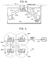
- Fig. 1a depicts an embodiment of the invention wherein a mobile workstation, or data processing unit 10, is in bidirectional communication with a network adapter, or base station 12, over an optical radiation communications channel.
- the base station 12 is coupled via a connector 14 to a wired local area network (LAN) 16.
- LAN local area network
- the base station 12 is disposed within or adjacent to a ceiling 18 and the mobile unit 10 is carried or is otherwise transported over a floor 20.
- the mobile unit 10 may be used in a stationary manner if desired. Ceiling mounting is not required for the base station 12 so long as there exists a substantially uncluttered transmission path between the base station 12 and the associated mobile unit or units 10.
- An uplink command channel (CC U ) uplink being from the mobile unit 10 to the base station 12, has a carrier frequency or wavelength that is offset from a downlink command channel (CC D ), downlink being from the base station 12 to the mobile unit 10, by an amount sufficient to prevent collisions between uplink and downlink command messages.
- an uplink data channel (DC U ) has a carrier frequency or wavelength that is offset from a downlink data channel (DC D ) by an amount sufficient to prevent collisions between uplink and downlink data messages.
- the communications channels are carried via an infrared (IR) data link having a preferred wavelength of approximately 1.4 microns, although presently available optical devices readily provide for operation within the range of approximately 750 nanometers to approximately 1000 nanometers.
- IR infrared
- the command channel is carried by a diffuse transmission lower bit-rate channel while the data channel is conveyed by a line-of-sight higher bit-rate channel. This permits the control channel of a mobile unit 10, including one that is just coming within range of a base station 12, to establish communication with the base station 12 and also possibly through a network to a host system, before reliable communication becomes feasible on the higher frequency data channel. The result is the provision of a reliable and efficient infrared data communications network, which is one expressed object of the invention.
- Fig. 1b there is shown a simplified block diagram of the base station 12.
- the base station 12 is coupled to the LAN 16 via the connector 14.
- Connector 14 is coupled to a network adapter transceiver 22 which in turn is coupled to an internal bus 24.
- the base station 12 includes a processor 26 that is bidirectionally coupled to a memory 28 that stores program-related and other data, including packets of data transmitted to or received from the mobile units 10.
- Processor 26 also communicates with a plurality of modulators and receivers, specifically a control modulator 30a, a control receiver 30b, a data modulator 30c and a data receiver 30d.
- IR modulators and receivers have inputs coupled to suitable infrared emitting or receiving devices such as laser diodes, LEDs and photodetectors.
- control modulator 30a and the data modulator 30c both have an output coupled to a transmit diode 1 (TD1).
- TD1 transmit diode 1
- the data modulator 30c is not coupled to the TD1 but is instead coupled to a second transmit diode (TD2).
- Mobile unit 10 includes a processor 32 coupled to an operator input device 34 and also coupled to an operator display device 36.
- Operator input device 34 may be a keyboard or any suitable data entry means.
- operator display device 36 may be a flat panel alphanumeric display or any suitable display means.
- processor 32 Also coupled to processor 32 is a memory 38 that stores program-related data and other data, such as packets of information received from or intended to be transmitted to the base station 12 and also an identification of the mobile unit 10.
- Also coupled to processor 32 are a plurality of command and data modulators and receivers 40a-40d.
- the command modulator 40a uplink
- the command receiver 40b downlink
- a second frequency f1' that is offset from f1.
- the data modulator 40c uplink
- the data receiver 40d downlink
- the data receivers of Figs 1b and 1c include demodulators and filters and operate in a conventional manner to extract the modulated bit stream from the received optical signals.
- the modulators of Figs. 1b and 1c operate in a conventional manner to modulate the optical output in accordance with a transmitted bit stream.
- both the command and data uplink information is transmitted via one transmit LED (TD) while the downlink command and data information is received by one receive photodetector (RD).
- TD transmit LED
- RD receive photodetector
- separate transmit LEDS and receive photodetectors could be used for separately transmitting and receiving the control and the data information.
- the wired LAN 16 may conform to any suitable network configuration.
- One suitable network protocol is known as TCP/IP, as described in detail in "Internetworking with TCP/IP Principles, Protocols, and Architectures" by Douglas E. Comer, Prentice Hall, New Jersey, 1988.
- the high bandwidth downlink data channel may operate at a wavelength of 900 nm and the uplink data channel may operate with a wavelength of 750 nm.
- Maximum output optical power for both is one Watt for a range of approximately five meters at a bit rate of from one to 10 Mbits/sec.
- the respective modulators may employ on-off pulsing, multi-carrier modulation or direct sequence spread spectrum modulation (DSSS), with the receivers including corresponding demodulating circuitry.
- DSSS is described in "Spread Spectrum in Communications", by Marvin K. Simon, Computer Science Press, Rockville, MD (1985).
- the low bandwidth downlink control channel may operate at a wavelength of 900 nm and the uplink control channel may operate with a wavelength of 750 nm.
- Output power for both is 10 mW for a range of 10 meters at a bit rate of 50 Kbits/sec.
- Manchester coding may be employed to obtain a DC null and modulation is preferably on-off although other techniques may also be employed.
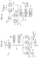
- Fig. 2 illustrates a plurality of the base stations 12 each of which is coupled to a wired LAN 16 which in turn is coupled to a host data processing system 50.
- the base stations 12 are disposed such that substantially symmetrical optical fields (42a-42d) associated with each are overlapping.
- substantially symmetrical optical fields (42a-42d) associated with each are overlapping.
- certain of the plurality of mobile units 10 are contained wholly within a single one of the fields while the mobile unit 10a is disposed within an overlapping region 44 between the fields 42a and 42b.
- the mobile unit 10c is disposed within a region not covered by any of the base stations 12. During use, the mobile units 10 can be expected to move about within a given region and to travel from one region to another.
- Fig. 3 illustrates another embodiment wherein the plurality of base stations 12 are each disposed within a separate enclosure or room (46a, 46b). In this embodiment there is no overlap between base station fields. So long as a mobile unit is within a room it is in communication with the associated base station 12. However, for those mobile units 10d which are illustrated to be within a hallway communication may be possible if properly aligned with a doorway or other opening into the enclosed area served by the base station 12.
- TDMA Time Division Multiple Access
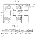
- a slot delimiter or synchronization (SYNC) field 48a is followed by a destination address field 48b and a source address field 48c.
- SYNC slot delimiter or synchronization
- the destination address would be that of a base station 12 while the source address would be that of the transmitting mobile unit 10.
- each of the mobile units is assigned an identifier or address that typically corresponds to a network address.
- the mobile unit 10 addresses may be hardwired or otherwise preassigned. Preferably, the addresses are dynamically assigned when communication is established between the network and the mobile unit 10.
- a next slot 48 field is a length field 48d which gives the length in bytes of the following data field 48e.
- the data field will typically be substantially smaller than a data field 48e associated with a data slot.
- a data integrity field typically a CRC field 48f.
- a further slot delimiter is provided by a trailer field 48g. It should be realized that this format is exemplary only and that a number of suitable formats can be devised. For example, similar results can be achieved through the use of the before mentioned DSSS modulation.
- Each slot on the wireless link may be a re-packetized frame of the wired network protocol, for example, TCP/IP.
- the destination address field 48b is the address of the base station 12, possibly but not necessarily its' IP address.
- the source address field 48c is either the base station 12 address (downlink) or the mobile unit 10 address (uplink), also possibly but not necessarily the mobile unit's IP address.
- the mobile wireless network thus far described must provide both media access control and data link control.
- Media access control relates to arbitration among the group of mobile units 10 for uplink access to the wireless medium of the infrared data link. Control requirements are asymmetric with respect to the uplink and the downlink channels. In the system of the invention the uplink and downlink are carried on separate optical wavelengths, thus avoiding collision.
- Typical control events that are conveyed between the mobile unit 10 to the base station 12 upon the lower bandwidth CC U channel may include, but are not limited to, the following.
- downlink control events there is no requirement for downlink media access control, since only the base station 12 uses the downlink channel, whereas the uplink channel must be shared by all of the mobile units within the associated group. It is assumed that the base station 12 avoids transmitting slots to mobile units which are not members of the base unit's group. That is, the base station 12 will only transmit to mobile units 10 with which the base station 12 has an established link. For the downlink path therefore, the mobile unit 10 need only recognize slots 48 having the mobile unit's address within the field 48b.
- Uplink responses to these control events from the mobile unit 10 to the base station 12 include the following.
- control messages could be carried in the same bit stream as the packets of data.
- control messages could be carried in the same bit stream as the packets of data.
- the inherent unreliability of such a high bandwidth channel makes the inclusion of control information on the channel disadvantageous for the reasons previously discussed.
- the wireless optical network taught by the invention overcomes the problem of establishing and maintaining high-bandwidth communication via an unreliable medium by separating the control channel from the data channel.
- the control channel requires a much smaller bandwidth than the data channel the propagation problems mentioned above are avoided.
- the control channel bandwidth can be made significantly smaller because, at most, one control message per data slot is required with the required control message being, at most, but a few hundred bits as compared to several thousand for a typical TCP/IP frame.
- control messages are only required to initially establish a transmission and, thus, the number of control messages per transmitted slot may be less than one.
- the low-bandwidth diffuse IR optical link may have greater range or sensitivity whereas the broad-band data channel optics are preferably made directional and require line-of-sight access to the base station 12 in order to maximize the received signal strength and to reduce multi-path propagation problems.
- the communication link establishment process may be begun early in the approach of the mobile unit 10 to the base station coverage region.
- the mobile unit 10e may begin the link establishment procedure at the indicated position while not yet within but approaching the data coverage region 42d of the associated base station 12.
- the longer-range diffuse IR control channel enables the control channel to maintain contact as the mobile unit 10 moves out of range of the base station 12, thereby permitting a more controlled handoff mechanism.
- Another advantage of the use of the separate low-bandwidth control channel is that it enables the mobile units 10 and the base station 12 to maintain contact temporarily even though the data channel is lost due to a momentary obstruction. This substantially reduces the communication overhead involved in losing a connection and then reestablishing it. This latter problem may be one of the limiting features of a wireless mobile network and is avoided if possible.
- control channel transmission rate can remain fixed while the data channel transmission rate may increase due to advances in network adapters and components.
- adapters with different data link speeds are enabled to coexist within a network.
- the separate control channel can also be employed as a simplified connection method for low-cost, low-bandwidth devices, such as simple printers, where the additional cost for high-bandwidth data channel devices may not be justified.
- the unit 10' may be such a printer that communicates with the wireless network only through the low-bandwidth CC U and CC D channels.
- a printer may be fixed in a given position within a base station 12 coverage area and not moved about, although no such restrictions are placed upon printer position.
- the data channels occupy the modulation spectrum above 400kHz and extend up to 1-10 MHz.
- the control channels occupy the modulation spectrum from approximately two kHz to approximately 300 kHz.
- the control and data channel signals are separated after the photodetector RD by electrical filtering.
- Each channel has its own receiver. Due to the lower bandwidth the control channel receiver (CR 40b) is less complex than the data channel receiver (DR40d). However, the data channel control logic is less complex than that of the control channel since only address recognition is required.
- a mobile unit 10 seeking a base station 12 transmits a request for connection on the control channel by using maximum optical power. Since the control channel is separate from the data channel, this asynchronous transmission does not interfere with uplink data transmission that may be in progress between the base station 12 and another mobile unit 10, although it may interfere with ongoing uplink control signals being generated by another mobile unit 10.
- the access mechanism for the uplink control channel is preferably a relatively simple ALOHA protocol of a type known in the art. This permits asynchronous requests for connection by an approaching mobile unit 10 to be handled in the same manner as requests from the existing group members. To improve the "fairness" of the ALOHA access under near/far conditions, the mobile units 10 have controllably variable power levels for the control signal transmission.
- the newly added member of the group is enabled to exchange control messages with the base station 12 using the uplink and downlink control channels.
- the downlink control channel is broadcast to all mobile units within the group and the control slot 48 address field 48b enables only the addressed mobile unit(s) to identify their control messages.
- the downlink data channel is also broadcast to all mobile units within the group and the corresponding data slot 48 address field 48b enables only the addressed mobile unit(s) to identify their data streams.
- the newly added mobile unit 10 synchronizes with the data link slot sequence by being assigned one slot number by the base station via the control channel. Thereafter the mobile unit 10 is expected to internally keep track of slot numbers, although it can request to be assigned a slot any number of times.
- the uplink and downlink paths employ the same set of slot numbers.
- a mobile unit 10 which has been authorized to use the uplink path waits for the beginning of its' authorized slot before sending data.
- a mobile unit 10 which has been instructed, via the control channel, to expect one or more packets of data from the downlink waits for the specified slot to occur and then begins to capture the information conveyed by that slot.
- a mobile unit can thus receive and transmit using a single assigned control or data slot.
- the base station 12 buffers within the memory 28 data received from the wired network or from the uplink data channel. Data packets are transmitted in the order received within specified priority levels. The base station 12 refrains from transmitting except when it has data or control information to broadcast.
- the diffuse command channel in the receiver and transmitter of the mobile unit 10 and base station 12 depends strongly on the optical collection mechanisms employed for the high-speed data channel.
- the data channel preferably has some directionality associated therewith to overcome multi-path effects and to increase light collection. If optical devices such as lenses or mirrors are employed, which tend to reduce the acceptance angles of the transmitters and detectors, insufficient diffuse infrared light may be produced or received when a line-of-sight relationship does not exist between the mobile unit 10 and the base station 12.
- control channel receiver (30b or 40b) uses a bandpass filter to exclude ambient light noise below 300 kHz and the data channel signals above 1 MHz.
- the data channel receiver (30d or 40d) uses a bandpass filter from approximately 400 kHz up to, for example, 20 MHz.
- the associated receiver and clock recovery requirements are relatively simple; although a finite state machine or similar means may be required to achieve real-time link control. Since the data channel transmission rate is high, for example 10 M Bit/s, the associated receiver and clock recovery requirements are more complex. However, the data channel requires only a relatively simple finite-state machine or similar means to recognize the associated address. If separate infrared emitters, such as TD1 and TD2, are employed it is preferable to include bandlimiting filters to match the characteristics of the associated receivers. In this case it is also desirable to employ different wavelengths for the control and data links. This results in a total of four wavelengths for implementing the wireless link, that is, two each for the uplink and the downlink paths.
- the two receivers may be connected to the same detector and the two transmitters to the same emitter, as depicted in Fig. 1c.
- control channel Separates the control channel from the data channel enables network adapters having various data channel transmission and receive rates to coexist.
- the control channel having standardized transmission and receive rates, provides a means for the mobile unit 10 and the base station 12 to determine the data transmission rate.
- control functions associated with the command and data channels, and also other logic required to operate the wireless link may be implemented in software executed by the processors 26 and 32. Alternately special purpose logic may be incorporated to realize these functions or some combination of these approaches may be employed. For some applications the processor and modulator and receiver circuits may all be implemented within a suitably programmed digital signal processor integrated circuit.
- data transmission can be made to "fall-back" to the diffuse transmission channel.
- the transmission rate may be appreciably slower, the link to the LAN 16 is not broken.
- Such a fall-back situation can be readily signalled from the base station 12 to the mobile unit 10 via a downlink control channel event after which the mobile unit 10 interprets subsequent diffuse channel receptions as data instead of command information.
- the high speed uplink channel can be eliminated altogether and all uplink traffic, both command and data, is conveyed by the low speed diffuse channel.
- the primary source of uplink data is expected to be keystrokes generated by an operator of the mobile unit 10.
- the high bandwidth uplink channel may be eliminated without significantly impacting response time or other user-noticeable system functionality.
Landscapes
- Engineering & Computer Science (AREA)
- Computing Systems (AREA)
- Physics & Mathematics (AREA)
- Electromagnetism (AREA)
- Computer Networks & Wireless Communication (AREA)
- Signal Processing (AREA)
- Mobile Radio Communication Systems (AREA)
- Optical Communication System (AREA)
- Computer And Data Communications (AREA)
- Small-Scale Networks (AREA)
Applications Claiming Priority (2)
| Application Number | Priority Date | Filing Date | Title |
|---|---|---|---|
| US60558690A | 1990-10-29 | 1990-10-29 | |
| US605586 | 1990-10-29 |
Publications (3)
| Publication Number | Publication Date |
|---|---|
| EP0483549A2 true EP0483549A2 (fr) | 1992-05-06 |
| EP0483549A3 EP0483549A3 (en) | 1993-01-20 |
| EP0483549B1 EP0483549B1 (fr) | 1996-09-04 |
Family
ID=24424316
Family Applications (1)
| Application Number | Title | Priority Date | Filing Date |
|---|---|---|---|
| EP91117072A Expired - Lifetime EP0483549B1 (fr) | 1990-10-29 | 1991-10-07 | Procédé et appareil de commande d'une liaison de données sans fil |
Country Status (4)
| Country | Link |
|---|---|
| US (1) | US5321542A (fr) |
| EP (1) | EP0483549B1 (fr) |
| JP (1) | JP2511591B2 (fr) |
| DE (1) | DE69121837T2 (fr) |
Cited By (17)
| Publication number | Priority date | Publication date | Assignee | Title |
|---|---|---|---|---|
| EP0584464A1 (fr) * | 1992-08-21 | 1994-03-02 | Kabushiki Kaisha Toshiba | Système pour la réception et l'émission de rayons infrarouges |
| EP0631401A1 (fr) * | 1993-06-22 | 1994-12-28 | Canon Kabushiki Kaisha | Procédé et appareil d'orientation dans un système de communication sans fils |
| FR2720573A1 (fr) * | 1994-05-31 | 1995-12-01 | Sat | Système de visite guidée automatique, borne de diffusion de messages et casque de réception de messages du système. |
| GB2300322A (en) * | 1995-04-25 | 1996-10-30 | Siemens Ag | Combined infra-red and telephone communications for computers |
| GB2303945A (en) * | 1995-07-28 | 1997-03-05 | James Goodfellow | Remote infra red personal computer access |
| GB2325822A (en) * | 1997-04-03 | 1998-12-02 | Sun Electric Uk Ltd | Wireless data transmission |
| US6031825A (en) * | 1992-08-18 | 2000-02-29 | Nokia Mobile Phones Limited | Infrared audio link in mobile phone |
| CN1078025C (zh) * | 1995-02-28 | 2002-01-16 | 日本电气株式会社 | 无线选呼接收机的数据发送控制装置和方法 |
| US6513070B1 (en) * | 1999-07-21 | 2003-01-28 | Unisys Corporation | Multi-channel master/slave interprocessor protocol |
| EP1076422A3 (fr) * | 1999-08-10 | 2003-05-21 | Armstrong World Industries, Inc. | Système pour communication de bus monte au plafond |
| GB2406987A (en) * | 2003-10-06 | 2005-04-13 | Nokia Corp | Dual channel optical communication link |
| DE19818088B4 (de) * | 1997-09-26 | 2005-09-01 | Fujitsu Ltd., Kawasaki | Optische Kommunikationseinheit |
| US7139488B1 (en) | 1997-09-26 | 2006-11-21 | Fujitsu Limited | Optical communication unit |
| WO2008056347A1 (fr) * | 2006-11-07 | 2008-05-15 | Elta Systems Ltd. | Systeme de communication optique en espace libre et procede pour l'exploiter |
| US7529227B2 (en) | 2003-04-04 | 2009-05-05 | Mitel Networks Corporation | System and method for PDA to PDA communication using a network portal |
| DE102010018749A1 (de) * | 2010-04-29 | 2011-11-03 | Deutsches Zentrum für Luft- und Raumfahrt e.V. | Hybrides Datenübertragungsverfahren für drahtlose Kommunikation |
| WO2019072630A1 (fr) * | 2017-10-12 | 2019-04-18 | HELLA GmbH & Co. KGaA | Système de communication pour un véhicule automobile |
Families Citing this family (98)
| Publication number | Priority date | Publication date | Assignee | Title |
|---|---|---|---|---|
| US6431451B1 (en) * | 1991-02-25 | 2002-08-13 | Intermec Ip Corp. | Hand-held data capture system with interchangeable modules |
| DE69326656T2 (de) * | 1992-07-17 | 2000-05-31 | Sun Microsystems, Inc. | Verfahren und Gerät zur Selbstorganisation in einem drahtlosen lokalen Netz |
| EP0589552B1 (fr) | 1992-09-08 | 2002-10-23 | Sun Microsystems, Inc. | Méthode et appareil pour le maintien de la connection des noeuds dans un réseau local sans fil |
| US5602667A (en) * | 1992-10-07 | 1997-02-11 | Unisys Corporation | Extended distance fiber optic interface |
| US6006090A (en) * | 1993-04-28 | 1999-12-21 | Proxim, Inc. | Providing roaming capability for mobile computers in a standard network |
| WO1995015624A1 (fr) * | 1993-12-02 | 1995-06-08 | Radiance Communications, Inc | Reseau local a infrarouge |
| US5546397A (en) * | 1993-12-20 | 1996-08-13 | Norand Corporation | High reliability access point for wireless local area network |
| US5960344A (en) | 1993-12-20 | 1999-09-28 | Norand Corporation | Local area network having multiple channel wireless access |
| KR960012849B1 (ko) * | 1993-12-23 | 1996-09-24 | 현대전자산업 주식회사 | 무선 프린터 공유 시스템 |
| US5754961A (en) | 1994-06-20 | 1998-05-19 | Kabushiki Kaisha Toshiba | Radio communication system including SDL having transmission rate of relatively high speed |
| US5845201A (en) * | 1994-07-01 | 1998-12-01 | Noller Communications, Inc. | Subscriber RF telephone system having distributed channel switching capability |
| CA2129199C (fr) * | 1994-07-29 | 1999-07-20 | Roger Y.M. Cheung | Methode et appareil pour raccorder en derivation un reseau local sans fil et un reseau local cable |
| CA2129193C (fr) * | 1994-07-29 | 1999-07-20 | Peter E. Reissner | Poursuite de points d'acces pour noeud de reseau de communication mobile sans fil |
| US6334219B1 (en) | 1994-09-26 | 2001-12-25 | Adc Telecommunications Inc. | Channel selection for a hybrid fiber coax network |
| WO1996011539A2 (fr) | 1994-10-04 | 1996-04-18 | Sdl, Inc. | Reseau local sans fil a diodes laser infrarouge |
| US5724168A (en) * | 1994-10-11 | 1998-03-03 | Spectrix Corporation | Wireless diffuse infrared LAN system |
| JPH08163130A (ja) * | 1994-12-02 | 1996-06-21 | Nec Corp | 無線lanのアクセス制御方式 |
| US5850518A (en) | 1994-12-12 | 1998-12-15 | Northrup; Charles J. | Access-method-independent exchange |
| USRE42236E1 (en) | 1995-02-06 | 2011-03-22 | Adc Telecommunications, Inc. | Multiuse subcarriers in multipoint-to-point communication using orthogonal frequency division multiplexing |
| US7280564B1 (en) | 1995-02-06 | 2007-10-09 | Adc Telecommunications, Inc. | Synchronization techniques in multipoint-to-point communication using orthgonal frequency division multiplexing |
| US5692127A (en) * | 1995-03-17 | 1997-11-25 | Apple Computer, Inc. | System for transmitting multiple pulses PPM control signal to wireless device to indicate collision in a wired network while placing data on the network |
| US5802469A (en) * | 1995-03-29 | 1998-09-01 | Kabushiki Kaisha Toshiba | Radio communication system selectable low speed bi-directional communication and high-speed down link communication |
| JP3378694B2 (ja) * | 1995-04-21 | 2003-02-17 | アルプス電気株式会社 | 情報伝送装置 |
| US5742602A (en) * | 1995-07-12 | 1998-04-21 | Compaq Computer Corporation | Adaptive repeater system |
| FI105740B (fi) * | 1995-09-29 | 2000-09-29 | Nokia Mobile Phones Ltd | Toimistoviestintäjärjestelmä |
| US5790291A (en) * | 1995-12-07 | 1998-08-04 | Lucent Technologies Inc. | Beam steering and tracking of laser communication links by dual-quadrant tracker and photodiode assembly |
| US5880863A (en) * | 1996-02-13 | 1999-03-09 | Gte Laboratories Incorporated | Reconfigurable ring system for the transport of RF signals over optical fibers |
| US5867661A (en) * | 1996-02-15 | 1999-02-02 | International Business Machines Corporation | Method and apparatus of using virtual sockets for reducing data transmitted over a wireless communication link between a client web browser and a host web server using a standard TCP protocol |
| US5754774A (en) * | 1996-02-15 | 1998-05-19 | International Business Machine Corp. | Client/server communication system |
| US6088592A (en) * | 1996-03-25 | 2000-07-11 | Airnet Communications Corporation | Wireless system plan using in band-translators with diversity backhaul to enable efficient depolyment of high capacity base transceiver systems |
| US5786923A (en) * | 1996-03-29 | 1998-07-28 | Dominion Communications, Llc | Point-to-multipoint wide area telecommunications network via atmospheric laser transmission through a remote optical router |
| US6931183B2 (en) | 1996-03-29 | 2005-08-16 | Dominion Lasercom, Inc. | Hybrid electro-optic cable for free space laser antennas |
| US6348986B1 (en) | 1996-03-29 | 2002-02-19 | Dominion Lasercom. Inc. | Wireless fiber-coupled telecommunication systems based on atmospheric transmission of laser signals |
| KR0174485B1 (ko) * | 1996-04-30 | 1999-04-01 | 김광호 | 전화선을 이용한 적외선 무선 통신 시스템 및 그 방법 |
| US6697415B1 (en) | 1996-06-03 | 2004-02-24 | Broadcom Corporation | Spread spectrum transceiver module utilizing multiple mode transmission |
| US5661727A (en) * | 1996-06-12 | 1997-08-26 | International Business Machines Corporation | Schemes to determine presence of hidden terminals in wireless networks environment and to switch between them |
| US5912752A (en) * | 1996-06-26 | 1999-06-15 | Lexmark International, Inc. | Method and apparatus for improving serial infrared asynchronous communication performance |
| US5838472A (en) * | 1996-07-03 | 1998-11-17 | Spectrix Corporation | Method and apparatus for locating a transmitter of a diffuse infrared signal within an enclosed area |
| US5812930A (en) * | 1996-07-10 | 1998-09-22 | International Business Machines Corp. | Information handling systems with broadband and narrowband communication channels between repository and display systems |
| BR9605275A (pt) * | 1996-10-17 | 1998-07-21 | H2T Handheld Technology Ltda | Sistema de comunicaçao por infravermelho difuso |
| US7006768B1 (en) * | 1997-01-02 | 2006-02-28 | Franklin Philip G | Method and apparatus for the zonal transmission of data using building lighting fixtures |
| WO2006041486A1 (fr) * | 2004-10-01 | 2006-04-20 | Franklin Philip G | Procede et appareil permettant la transmission zonale de donnees au moyen des installations d'eclairage de batiments |
| US5951650A (en) * | 1997-01-31 | 1999-09-14 | International Business Machines Corporation | Session traffic splitting using virtual internet protocol addresses associated with distinct categories of application programs irrespective of destination IP address |
| US6081356A (en) * | 1997-05-27 | 2000-06-27 | Steelcase Development Inc. | Integrated optical ports |
| US6070184A (en) * | 1997-08-28 | 2000-05-30 | International Business Machines Corporation | Server-side asynchronous form management |
| US6035324A (en) * | 1997-08-28 | 2000-03-07 | International Business Machines Corporation | Client-side asynchronous form management |
| US6424660B2 (en) * | 1997-10-10 | 2002-07-23 | Intel Corporation | Addressable distributed wireless remote control system |
| FR2772533B1 (fr) * | 1997-12-15 | 2001-09-28 | Inst Nat Rech Inf Automat | Dispositif d'interconnexion entre segments de reseaux communiquant selon des protocoles de formats differents, et procede correspondant |
| US6567855B1 (en) * | 1998-01-02 | 2003-05-20 | Intel Corporation | Portable processing system with always on, always connected capability |
| US6097948A (en) * | 1998-01-29 | 2000-08-01 | Telefonaktiebolaget L M Ericsson (Publ) | Signaling channel firewall for communications between wireless networks |
| US6271815B1 (en) * | 1998-02-20 | 2001-08-07 | University Of Hong Kong | Handy information display system |
| CA2287304C (fr) | 1998-03-03 | 2003-10-21 | Itron, Inc. | Methode et systeme de lecture de compteurs intelligents de service d'utilite publique |
| WO1999052231A1 (fr) * | 1998-04-03 | 1999-10-14 | Ericsson Inc. | Systeme de liaisons optiques et procede associe |
| JP4110613B2 (ja) * | 1998-04-22 | 2008-07-02 | ソニー株式会社 | 送信装置、送信方法、提供媒体、並びに伝送システム |
| US6337856B1 (en) | 1998-05-20 | 2002-01-08 | Steelcase Development Corporation | Multimedia data communications system |
| US6298047B1 (en) | 1998-05-20 | 2001-10-02 | Steelcase Development Inc. | Method and apparatus for establishing a data link between a portable data communications device and an interface circuit |
| US6359711B1 (en) | 1998-05-20 | 2002-03-19 | Steelcase Development Corporation | System and method for supporting a worker in a distributed work environment |
| JPH11338587A (ja) * | 1998-05-26 | 1999-12-10 | Matsushita Electric Ind Co Ltd | 非接触情報伝送装置 |
| US6934255B1 (en) | 1999-02-02 | 2005-08-23 | Packeteer, Inc. | Internet over satellite apparatus |
| US6690657B1 (en) | 2000-02-25 | 2004-02-10 | Berkeley Concept Research Corporation | Multichannel distributed wireless repeater network |
| JP4902044B2 (ja) | 1999-09-24 | 2012-03-21 | シャープ株式会社 | 半導体レーザ装置、光伝送装置、光伝送システム、電子機器、制御装置、接続コネクタ、通信装置、ならびに光伝送方法、データ送受信方法 |
| AU2001280589A1 (en) * | 2000-07-19 | 2002-01-30 | Joseph R. Child | Network and stations for free space optical communication |
| US20020040388A1 (en) * | 2000-08-15 | 2002-04-04 | Lockheed Martin Corporation | Method and apparatus for delivering services in a constrained environment |
| US7386238B2 (en) | 2000-08-15 | 2008-06-10 | Lockheed Martin Corporation | Method and system for infrared data communications |
| US20020054412A1 (en) * | 2000-09-20 | 2002-05-09 | Keller Robert C. | Optical wireless communication system with multiple receivers |
| GB0025463D0 (en) * | 2000-10-17 | 2000-11-29 | Isis Innovation | Improvements in or relating to optical wireless communications |
| WO2002073845A2 (fr) * | 2001-03-09 | 2002-09-19 | Lightpointe Communications, Inc. | Reseau de communication optique en espace libre |
| US20020191252A1 (en) * | 2001-05-10 | 2002-12-19 | Pugel Michel Anthony | Economical extension of the operating distance of an RF remote link accommodating IR remote controls having differing IR carrier frequencies |
| US6895252B2 (en) | 2001-05-10 | 2005-05-17 | Thomson Licensing Sa | Economical extension of the operating distance of an RF remote link accommodating information signals having differing carrier frequencies |
| JP4124123B2 (ja) * | 2001-08-16 | 2008-07-23 | エヌエックスピー ビー ヴィ | データ及びクロックリカバリ回路、並びに複数の上記回路を有する装置 |
| US7103021B2 (en) | 2001-09-25 | 2006-09-05 | Qualcomm Incorporated | Method and apparatus for communications of data rate control information in a CDMA communication system |
| US7200567B2 (en) * | 2002-01-04 | 2007-04-03 | Lockheed Martin Corporation | Purchasing aid logistics appliance and method for use |
| DE10223376A1 (de) * | 2002-05-25 | 2003-12-11 | Efkon Ag Graz | Verfahren und Vorrichtung zur optischen Datenübertragung |
| JP4718748B2 (ja) * | 2002-06-14 | 2011-07-06 | 日本電気株式会社 | 通信制御方法、サーバ通信装置、クライアント通信装置及び通信制御プログラム |
| US20040015591A1 (en) * | 2002-07-18 | 2004-01-22 | Wang Frank Xiao-Dong | Collective TCP control for improved wireless network performance |
| US7343398B1 (en) | 2002-09-04 | 2008-03-11 | Packeteer, Inc. | Methods, apparatuses and systems for transparently intermediating network traffic over connection-based authentication protocols |
| US7725842B2 (en) * | 2003-04-24 | 2010-05-25 | Bronkema Valentina G | Self-attainable analytic tool and method for adaptive behavior modification |
| US7132953B2 (en) * | 2003-06-26 | 2006-11-07 | Lear Corporation | Spring sensor assembly for a vehicle seat cushion |
| US7399205B2 (en) | 2003-08-21 | 2008-07-15 | Hill-Rom Services, Inc. | Plug and receptacle having wired and wireless coupling |
| JP3891167B2 (ja) * | 2003-10-24 | 2007-03-14 | ブラザー工業株式会社 | ネットワーク装置管理システム、ネットワーク装置管理装置、およびネットワーク装置管理プログラム |
| JP4362384B2 (ja) * | 2004-02-02 | 2009-11-11 | 株式会社シマノ | 両軸受リール及びそれに用いるスプール制動装置 |
| US20050238357A1 (en) * | 2004-04-27 | 2005-10-27 | Farrell Thomas C | Laser communication system with adaptive data rates |
| US20050254506A1 (en) * | 2004-05-11 | 2005-11-17 | Derek Edward Davout Gladding | Apparatus and method for transporting data over a ring structure |
| US7924167B2 (en) * | 2004-06-22 | 2011-04-12 | Agere Systems Inc. | Remote control code filtering used for relaying of remote control codes |
| AU2005322833A1 (en) | 2005-01-06 | 2006-07-13 | Tervela, Inc. | A caching engine in a messaging system |
| AU2005322969A1 (en) * | 2005-01-06 | 2006-07-13 | Tervela, Inc. | End-to-end publish/subscribe middleware architecture |
| US7884735B2 (en) | 2005-02-11 | 2011-02-08 | Hill-Rom Services, Inc. | Transferable patient care equipment support |
| US20080031245A1 (en) * | 2006-03-06 | 2008-02-07 | Nokia Corporation | Uplink signaling for multicast transmission |
| US8717965B2 (en) * | 2006-12-01 | 2014-05-06 | Apple Inc. | Enhancing wimax performance with subscriber stations acting as ad hoc repeaters |
| US8032030B2 (en) * | 2008-05-30 | 2011-10-04 | Freescale Semiconductor, Inc. | Multiple core system |
| US8294483B2 (en) * | 2008-05-30 | 2012-10-23 | Freescale Semiconductor, Inc. | Testing of multiple integrated circuits |
| JP2016058887A (ja) * | 2014-09-09 | 2016-04-21 | パナソニックIpマネジメント株式会社 | 可視光通信装置、及び、受信装置 |
| US20160226585A1 (en) * | 2015-02-02 | 2016-08-04 | Blackberry Limited | Computing devices and methods for data transmission |
| US10395769B2 (en) | 2015-12-16 | 2019-08-27 | Hill-Rom Services, Inc. | Patient care devices with local indication of correspondence and power line interconnectivity |
| CN115462009A (zh) * | 2020-05-08 | 2022-12-09 | 昕诺飞控股有限公司 | 光学无线通信系统的功率节省 |
| CN112468555B (zh) * | 2020-11-16 | 2023-11-07 | 福建多多云科技有限公司 | 基于云手机的宏命令群控方案 |
| US12186241B2 (en) | 2021-01-22 | 2025-01-07 | Hill-Rom Services, Inc. | Time-based wireless pairing between a medical device and a wall unit |
| US12279999B2 (en) | 2021-01-22 | 2025-04-22 | Hill-Rom Services, Inc. | Wireless configuration and authorization of a wall unit that pairs with a medical device |
Family Cites Families (18)
| Publication number | Priority date | Publication date | Assignee | Title |
|---|---|---|---|---|
| US4259746A (en) * | 1979-10-26 | 1981-03-31 | Sandstedt Gary O | Electrical communications system |
| EP0054582B1 (fr) * | 1980-12-23 | 1986-03-19 | International Business Machines Corporation | Système de communication dans lequel les données sont transmises entre des stations terminales et des stations satellites par des signaux infrarouges |
| GB2101828B (en) * | 1981-07-14 | 1985-02-13 | Standard Telephones Cables Ltd | Exchange cabling |
| US4574305A (en) * | 1983-08-11 | 1986-03-04 | Tocum, Incorporated | Remote hub television and security systems |
| JPS60182239A (ja) * | 1984-02-29 | 1985-09-17 | Fujitsu Kiden Ltd | スイツチ操作状態の判別方式 |
| JPS60246137A (ja) * | 1984-05-22 | 1985-12-05 | Canon Inc | 光通信方式 |
| DE3572430D1 (en) * | 1985-04-02 | 1989-09-21 | Ibm | Infrared communication system |
| JPS62250740A (ja) * | 1986-04-24 | 1987-10-31 | Matsushita Electric Works Ltd | デ−タ伝送システム |
| GB8618424D0 (en) * | 1986-07-29 | 1986-09-03 | Leslie I M | Data rate channel for digital network |
| US4807222A (en) * | 1986-08-25 | 1989-02-21 | American Telephone And Telegraph Company At&T Bell Laboratories | Cordless accessed high-speed high-capacity local area networks |
| US4826742A (en) * | 1988-01-21 | 1989-05-02 | International Fuel Cells Corporation | Water and heat management in solid polymer fuel cell stack |
| US4931250A (en) * | 1988-05-12 | 1990-06-05 | Codex Corporation | Multimode modem |
| US4884266A (en) * | 1988-08-09 | 1989-11-28 | Sun Microsystems, Inc. | Variable speed local area network |
| US5144466A (en) * | 1988-10-04 | 1992-09-01 | Canon Kabushiki Kaisha | Optical fiber communication method and multimedia optical fiber network using the same |
| JPH0298253A (ja) * | 1988-10-04 | 1990-04-10 | Canon Inc | マルチメディア光ファイバネットワーク |
| GB8825498D0 (en) * | 1988-11-01 | 1988-12-07 | Bicc Plc | Infrared communications network |
| JP2523857B2 (ja) * | 1989-03-08 | 1996-08-14 | 松下電器産業株式会社 | 伝送移動通信システム |
| US5029183A (en) * | 1989-06-29 | 1991-07-02 | Symbol Technologies, Inc. | Packet data communication network |
-
1991
- 1991-08-07 JP JP22215791A patent/JP2511591B2/ja not_active Expired - Fee Related
- 1991-10-07 EP EP91117072A patent/EP0483549B1/fr not_active Expired - Lifetime
- 1991-10-07 DE DE69121837T patent/DE69121837T2/de not_active Expired - Lifetime
-
1993
- 1993-11-08 US US08/148,190 patent/US5321542A/en not_active Expired - Lifetime
Cited By (28)
| Publication number | Priority date | Publication date | Assignee | Title |
|---|---|---|---|---|
| US6031825A (en) * | 1992-08-18 | 2000-02-29 | Nokia Mobile Phones Limited | Infrared audio link in mobile phone |
| EP0584464A1 (fr) * | 1992-08-21 | 1994-03-02 | Kabushiki Kaisha Toshiba | Système pour la réception et l'émission de rayons infrarouges |
| EP0631401A1 (fr) * | 1993-06-22 | 1994-12-28 | Canon Kabushiki Kaisha | Procédé et appareil d'orientation dans un système de communication sans fils |
| US5526161A (en) * | 1993-06-22 | 1996-06-11 | Canon Kabushiki Kaisha | Communication control method and apparatus |
| FR2720573A1 (fr) * | 1994-05-31 | 1995-12-01 | Sat | Système de visite guidée automatique, borne de diffusion de messages et casque de réception de messages du système. |
| CN1078025C (zh) * | 1995-02-28 | 2002-01-16 | 日本电气株式会社 | 无线选呼接收机的数据发送控制装置和方法 |
| GB2300322A (en) * | 1995-04-25 | 1996-10-30 | Siemens Ag | Combined infra-red and telephone communications for computers |
| GB2300322B (en) * | 1995-04-25 | 1997-04-09 | Siemens Ag | System for locally flexible telecommunication |
| GB2303945B (en) * | 1995-07-28 | 2000-08-16 | James Goodfellow | Improvements in or relating to computers |
| GB2303945A (en) * | 1995-07-28 | 1997-03-05 | James Goodfellow | Remote infra red personal computer access |
| GB2325822A (en) * | 1997-04-03 | 1998-12-02 | Sun Electric Uk Ltd | Wireless data transmission |
| GB2325822B (en) * | 1997-04-03 | 2002-06-19 | Sun Electric Uk Ltd | Wireless data transmission |
| US6917304B1 (en) | 1997-04-03 | 2005-07-12 | Snap-On Equipment Limited | Wireless mutliplex data transmission system |
| US7188527B2 (en) | 1997-04-03 | 2007-03-13 | Snap-On Equipment Limited | Apparatus and method for vibration analysis of a machine or other article |
| DE19818088B4 (de) * | 1997-09-26 | 2005-09-01 | Fujitsu Ltd., Kawasaki | Optische Kommunikationseinheit |
| US7139488B1 (en) | 1997-09-26 | 2006-11-21 | Fujitsu Limited | Optical communication unit |
| US6513070B1 (en) * | 1999-07-21 | 2003-01-28 | Unisys Corporation | Multi-channel master/slave interprocessor protocol |
| EP1076422A3 (fr) * | 1999-08-10 | 2003-05-21 | Armstrong World Industries, Inc. | Système pour communication de bus monte au plafond |
| US7529227B2 (en) | 2003-04-04 | 2009-05-05 | Mitel Networks Corporation | System and method for PDA to PDA communication using a network portal |
| GB2406987A (en) * | 2003-10-06 | 2005-04-13 | Nokia Corp | Dual channel optical communication link |
| US7636523B2 (en) | 2003-10-06 | 2009-12-22 | Nokia Corporation | Communication link for communicating data |
| WO2008056347A1 (fr) * | 2006-11-07 | 2008-05-15 | Elta Systems Ltd. | Systeme de communication optique en espace libre et procede pour l'exploiter |
| US8103167B2 (en) | 2006-11-07 | 2012-01-24 | Elta Systems Ltd. | System for free space optical communication and method for operation thereof |
| DE102010018749A1 (de) * | 2010-04-29 | 2011-11-03 | Deutsches Zentrum für Luft- und Raumfahrt e.V. | Hybrides Datenübertragungsverfahren für drahtlose Kommunikation |
| DE102010018749B4 (de) * | 2010-04-29 | 2012-06-14 | Deutsches Zentrum für Luft- und Raumfahrt e.V. | Hybrides Datenübertragungsverfahren für drahtlose Kommunikation |
| DE102010018749C5 (de) * | 2010-04-29 | 2016-10-27 | Deutsches Zentrum für Luft- und Raumfahrt e.V. | Hybrides Datenübertragungsverfahren für drahtlose Kommunikation |
| WO2019072630A1 (fr) * | 2017-10-12 | 2019-04-18 | HELLA GmbH & Co. KGaA | Système de communication pour un véhicule automobile |
| CN111213329A (zh) * | 2017-10-12 | 2020-05-29 | 黑拉有限责任两合公司 | 用于机动车的通信系统 |
Also Published As
| Publication number | Publication date |
|---|---|
| DE69121837D1 (de) | 1996-10-10 |
| JPH04249442A (ja) | 1992-09-04 |
| US5321542A (en) | 1994-06-14 |
| JP2511591B2 (ja) | 1996-06-26 |
| DE69121837T2 (de) | 1997-04-30 |
| EP0483549A3 (en) | 1993-01-20 |
| EP0483549B1 (fr) | 1996-09-04 |
Similar Documents
| Publication | Publication Date | Title |
|---|---|---|
| EP0483549B1 (fr) | Procédé et appareil de commande d'une liaison de données sans fil | |
| US5181200A (en) | Handoff method and apparatus for mobile wireless workstation | |
| EP0483550B1 (fr) | Coordination de l'accès, par une pluralité de stations de base, à un milieu "sans fil" | |
| US5917629A (en) | Transceiver for extending a CSMA/CD network for wireless communication | |
| EP1219047B1 (fr) | Reseau bande de base sans fil assurant des transmissions isochrones | |
| US4451827A (en) | Local area communication network | |
| EP0196347B1 (fr) | Système de communication par infrarouge | |
| EP0439008B1 (fr) | Communication en duplex intégral de station à station dans un réseau local à passage de jeton | |
| US7177661B2 (en) | Communication between wireless access points over LAN cabling | |
| EP3635883B1 (fr) | Système de communication optique sans fil et réseau de communication sans fil optique adaptatif | |
| US5418785A (en) | Multiple-channel token ring network with single optical fiber utilizing subcarrier multiplexing with a dedicated control channel | |
| KR20050051709A (ko) | 유선 lan 하부구조를 위한 무선 lan 접속 포인트간협동을 위한 방법 및 장치 | |
| US6456410B1 (en) | Optical data communication system and method | |
| JPS62269439A (ja) | トランシ−バ |
Legal Events
| Date | Code | Title | Description |
|---|---|---|---|
| PUAI | Public reference made under article 153(3) epc to a published international application that has entered the european phase |
Free format text: ORIGINAL CODE: 0009012 |
|
| AK | Designated contracting states |
Kind code of ref document: A2 Designated state(s): DE FR GB |
|
| 17P | Request for examination filed |
Effective date: 19920817 |
|
| PUAL | Search report despatched |
Free format text: ORIGINAL CODE: 0009013 |
|
| AK | Designated contracting states |
Kind code of ref document: A3 Designated state(s): DE FR GB |
|
| 17Q | First examination report despatched |
Effective date: 19950629 |
|
| GRAH | Despatch of communication of intention to grant a patent |
Free format text: ORIGINAL CODE: EPIDOS IGRA |
|
| GRAH | Despatch of communication of intention to grant a patent |
Free format text: ORIGINAL CODE: EPIDOS IGRA |
|
| GRAA | (expected) grant |
Free format text: ORIGINAL CODE: 0009210 |
|
| AK | Designated contracting states |
Kind code of ref document: B1 Designated state(s): DE FR GB |
|
| REF | Corresponds to: |
Ref document number: 69121837 Country of ref document: DE Date of ref document: 19961010 |
|
| ET | Fr: translation filed | ||
| PLBE | No opposition filed within time limit |
Free format text: ORIGINAL CODE: 0009261 |
|
| STAA | Information on the status of an ep patent application or granted ep patent |
Free format text: STATUS: NO OPPOSITION FILED WITHIN TIME LIMIT |
|
| 26N | No opposition filed | ||
| PGFP | Annual fee paid to national office [announced via postgrant information from national office to epo] |
Ref country code: FR Payment date: 19991018 Year of fee payment: 9 |
|
| PG25 | Lapsed in a contracting state [announced via postgrant information from national office to epo] |
Ref country code: FR Free format text: LAPSE BECAUSE OF NON-PAYMENT OF DUE FEES Effective date: 20010629 |
|
| REG | Reference to a national code |
Ref country code: FR Ref legal event code: ST |
|
| REG | Reference to a national code |
Ref country code: GB Ref legal event code: IF02 |
|
| REG | Reference to a national code |
Ref country code: GB Ref legal event code: 746 Effective date: 20080925 |
|
| PGFP | Annual fee paid to national office [announced via postgrant information from national office to epo] |
Ref country code: DE Payment date: 20091027 Year of fee payment: 19 |
|
| PGFP | Annual fee paid to national office [announced via postgrant information from national office to epo] |
Ref country code: GB Payment date: 20101022 Year of fee payment: 20 |
|
| REG | Reference to a national code |
Ref country code: DE Ref legal event code: R119 Ref document number: 69121837 Country of ref document: DE Effective date: 20110502 |
|
| REG | Reference to a national code |
Ref country code: GB Ref legal event code: PE20 Expiry date: 20111006 |
|
| PG25 | Lapsed in a contracting state [announced via postgrant information from national office to epo] |
Ref country code: GB Free format text: LAPSE BECAUSE OF EXPIRATION OF PROTECTION Effective date: 20111006 |
|
| PG25 | Lapsed in a contracting state [announced via postgrant information from national office to epo] |
Ref country code: DE Free format text: LAPSE BECAUSE OF NON-PAYMENT OF DUE FEES Effective date: 20110502 |