EP0483605A2 - Arrangement pour fixer un élément de chargement - Google Patents
Arrangement pour fixer un élément de chargement Download PDFInfo
- Publication number
- EP0483605A2 EP0483605A2 EP91117686A EP91117686A EP0483605A2 EP 0483605 A2 EP0483605 A2 EP 0483605A2 EP 91117686 A EP91117686 A EP 91117686A EP 91117686 A EP91117686 A EP 91117686A EP 0483605 A2 EP0483605 A2 EP 0483605A2
- Authority
- EP
- European Patent Office
- Prior art keywords
- arrangement according
- locking plate
- loading unit
- fitting
- corner
- Prior art date
- Legal status (The legal status is an assumption and is not a legal conclusion. Google has not performed a legal analysis and makes no representation as to the accuracy of the status listed.)
- Withdrawn
Links
- 230000015572 biosynthetic process Effects 0.000 claims 1
- 238000005755 formation reaction Methods 0.000 claims 1
- 230000008878 coupling Effects 0.000 description 10
- 238000010168 coupling process Methods 0.000 description 10
- 238000005859 coupling reaction Methods 0.000 description 10
- 238000004873 anchoring Methods 0.000 description 2
- 238000003780 insertion Methods 0.000 description 2
- 230000037431 insertion Effects 0.000 description 2
- FGRBYDKOBBBPOI-UHFFFAOYSA-N 10,10-dioxo-2-[4-(N-phenylanilino)phenyl]thioxanthen-9-one Chemical compound O=C1c2ccccc2S(=O)(=O)c2ccc(cc12)-c1ccc(cc1)N(c1ccccc1)c1ccccc1 FGRBYDKOBBBPOI-UHFFFAOYSA-N 0.000 description 1
- 239000011324 bead Substances 0.000 description 1
- 238000004519 manufacturing process Methods 0.000 description 1
Images


Classifications
-
- B—PERFORMING OPERATIONS; TRANSPORTING
- B65—CONVEYING; PACKING; STORING; HANDLING THIN OR FILAMENTARY MATERIAL
- B65D—CONTAINERS FOR STORAGE OR TRANSPORT OF ARTICLES OR MATERIALS, e.g. BAGS, BARRELS, BOTTLES, BOXES, CANS, CARTONS, CRATES, DRUMS, JARS, TANKS, HOPPERS, FORWARDING CONTAINERS; ACCESSORIES, CLOSURES, OR FITTINGS THEREFOR; PACKAGING ELEMENTS; PACKAGES
- B65D90/00—Component parts, details or accessories for large containers
- B65D90/0006—Coupling devices between containers, e.g. ISO-containers
- B65D90/0013—Twist lock
-
- B—PERFORMING OPERATIONS; TRANSPORTING
- B60—VEHICLES IN GENERAL
- B60P—VEHICLES ADAPTED FOR LOAD TRANSPORTATION OR TO TRANSPORT, TO CARRY, OR TO COMPRISE SPECIAL LOADS OR OBJECTS
- B60P7/00—Securing or covering of load on vehicles
- B60P7/06—Securing of load
- B60P7/13—Securing freight containers or forwarding containers on vehicles
-
- B—PERFORMING OPERATIONS; TRANSPORTING
- B65—CONVEYING; PACKING; STORING; HANDLING THIN OR FILAMENTARY MATERIAL
- B65D—CONTAINERS FOR STORAGE OR TRANSPORT OF ARTICLES OR MATERIALS, e.g. BAGS, BARRELS, BOTTLES, BOXES, CANS, CARTONS, CRATES, DRUMS, JARS, TANKS, HOPPERS, FORWARDING CONTAINERS; ACCESSORIES, CLOSURES, OR FITTINGS THEREFOR; PACKAGING ELEMENTS; PACKAGES
- B65D90/00—Component parts, details or accessories for large containers
- B65D90/0026—Corner fittings characterised by shape, configuration or number of openings
Definitions
- An arrangement for securing a loading unit (container, tank container, flat, pallet) to a locking element (rotary lock or thorn) present on a vehicle loading surface with the features specified in the first part of claim 1 is known from EP 0 189 054 A2.
- a locking plate can be led out of the corner opening of a lower corner fitting provided on the loading unit in such a way that it can be fixed to a locking element with a side elongated hole.
- the known arrangement is designed so that a coupling to the locking element is only possible in a single relative position of the loading unit with respect to the locking element and only in the area of the front and / or rear edge of the loading unit. If the length of the loading unit in the direction of travel does not correspond to the standardized distance between two locking elements on the loading surface, then only securing around the front or rear edge of the loading unit with the resulting risk of tipping is possible.
- DD 283 115 A5 it is known to provide locking plates, each with an elongated hole, for engaging the rotary locks of a spreader on the upper side of a frame which is used to fasten a container.
- the locking plates are extendable and rotatable in order to pass a rotary lock head which is present on the frame in the same area.
- the invention has for its object to provide an arrangement which ensures greater flexibility with respect to the mutual position when securing a loading unit on a locking element and thereby enables better utilization of the available loading area.
- the locking plate which can then be fixed to the loading unit in at least two different positions and has an elongated hole for engaging a spike or rotary lock that is customary in trolleys or pallets, enables the loading unit to be rotated either in different directions, for example rotated by 90 ° or in one direction to secure offset positions on the carrier. If on a vehicle, the loading area of which is provided with locking elements for the transport of ISO-standardized loading units, those with previously not standardized length dimensions are to be transported, the invention offers the possibility of anchoring the locking plates in the respective fittings in such a way that a coupling to a existing locking element in different relative assignments is possible.
- the arrangement according to claim 2 enables particularly simple operation of the locking plate which can be rotated in this case.
- a square plan of the loading unit according to claim 3 has the advantage over a rectangular one that the units can be loaded as they stand on the stacking place. The loading personnel do not have to pay attention to a correct arrangement.
- the plurality of elongated holes provided according to claim 5 along two opposite sides enables particularly good utilization of the existing loading area, since the loading unit can be fixed to a locking element in a plurality of positions lying close to one another. With simultaneous fixation on two adjacent locking elements, security is also increased.
- the dimensions given in claims 4 and 6 are particularly advantageous for wagons and platforms according to the ISO standard.
- the side length of 2433 mm enables the connection of two loading units, which are at a distance of 106 mm from each other, by means of a coupling bar, which has two fastening elements provided at a distance of 280 mm, which engage in the elongated holes in the corner fittings of the two containers.
- the space of 106 mm between the two loading units enables the coupling bolt to be fixed to a mandrel or rotary lock of a wagon.
- Claims 7 to 20 relate to preferred practical designs of the locking plate and the fitting which accommodates it and is arranged on the loading unit.
- the loading unit can be locked in two positions rotated by 90 ° on the loading surface, which in the sense of greater flexibility in the handling of loading units with a square base can be useful.
- the designs according to claims 8 to 11 relate to particularly easy to manufacture and robust fittings.
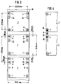
- the corner fitting 1 shown in FIGS. 1 and 2 has a base plate 2 which is provided with a circular hole 12.
- the diameter of the hole 12 is slightly larger than the length of the head 19 of a locking element, i. H. a mandrel or rotary lock.
- the locking plate 3 is round and rotatably mounted in the recess 26.
- an elongated hole 23 is made, which in turn corresponds in length and width to the head 19 of the locking element.
- the dimensions of the mandrels on railway wagons are 100 mm x 50 mm and those of rotary locks on road vehicles are 100 mm x 57 mm.
- the elongated hole 23 should have a length of approximately 106 mm and a width of approximately 63 mm, taking into account the necessary play and tolerances.
- a handle 29 is attached to the locking plate 3 for simple operation and for clearly identifying the position of the elongated hole 23.
- screw bolts 27 or cover plates, not shown
- cover plates are provided, which are designed such that the screw head presses the locking plate 3 sliding or locking in its seat formed by the recess 26. It is secured against twisting either by the friction associated with the contact pressure or, if countersunk screws are used, in that the screw head engages in recesses 28 in the locking plate 3.
- FIG. 2 shows the corner fitting 1 shown in plan view in section in section.
- the approximately hammer-shaped head 19 of a rotary lock is not shown in Figure 1 for reasons of clarity.
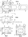
- FIG. 3 shows - not to scale - how square loading units 7 can be secured on a conventional railway wagon W by means of locking elements A.
- the loading units 7 are equipped with corner fittings 1 and on two opposite sides at a distance of 280 mm each with at least one additional elongated hole 24.
- the distance between two corner fittings 1 on each side of a square loading unit 7 is 2259 mm according to the ISO standard for the distance between two locking elements A transverse to the direction of travel. 2433 mm was chosen as the side length of the loading unit 7, which represents the lower tolerance limit for the width of ISO containers.
- the ISO standard width is 2438 mm.
- the specified gaps are large enough to be able to easily remove any loading unit 7 from the carrier wagon or put it on again by means of a forklift or a crane.
- the loading units are close enough to prevent each other from tipping over. This is particularly important if they are only attached to two corner fittings 1 located on an axis running transversely to the direction of travel.
- the side length of a loading unit 7 of 2433 mm has the particular advantage that two adjacent loading units, the corner fittings 1 of which are at a distance of 280 mm from one another, leave a space of 106 mm free.
- the space mentioned is dimensioned sufficiently for a locking element A, with the aid of which the coupling bolt 35, which has an elongated hole there, is fixed. In this way, two loading units 7 can be attached to a single locking element A.
- corner fitting 1 leads to a significant gain in flexibility when loading wagons W with loading units 7, it may be advantageous to equip two, three or all four corner fittings with rotatable locking plates 3.
- the invention can also be used advantageously in the case of rectangular units which can have, for example, a base area of 2433 mm ⁇ 1200 mm and are arranged in pairs in the longitudinal direction on a carrier wagon W. With such small loading units, attachment to only one locking element is sufficient. To protect against twisting or slipping, the units can be connected in pairs by bolts, which are similar to the coupling bolt 35 shown in FIG. 4.
- the corner fitting 10 shown in detail in FIGS. 5 to 7 consists of an 8 mm thick base plate 11 with a centrally arranged circular hole 12, an essentially triangular cover plate 13, an angle profile element 14 and three corner supports 15, 16.
- the angle profile element 14 has with its Outer edge to the outer corner of the loading unit, the outer boundary of which is indicated at 17 in FIG.
- the cover plate 13 can also be part of the bottom of the loading unit 17 itself.
- a cutout 18 with parallel edges is provided, which is open towards the base plate 11, but in its upper, round boundary corresponds to the opening on the end face of a corner fitting according to ISO 1161.
- the support 16 opposite the outer edge is formed by a square profile piece.
- Each of the two further supports 15 consists of a rectangular profile piece and is welded to the relevant end of the angle profile element 14.
- the support 16 is square in cross-section, while the supports 15 are dimensioned such that they project into the corner fitting 1 to the same extent as the support 16 in connection with the flanks of the angle profile element 14.
- the triangular cover plate 13 shown in dash-dotted lines in FIG. 5 lies on the upper surfaces of the supports 15 and 16 and has an upper surface which is flush with the upper end of the angle profile element 14.
- the angle profile element 14 can pass upwards and form a corner element of the loading unit 17 or its base group.
- a locking plate 20 is inserted into the corner fitting 10 according to FIGS. 5 to 7, which comprises a head 21 lying inside the corner fitting 10 and a shoulder 22 protruding laterally from the corner fitting 10.
- the head 21 of the locking plate 20 has an essentially cross-beam-like shape and is provided with an elongated hole 23, the center of which coincides with the center of the circular hole 12 present in the base plate 11 of the corner fitting 10 and the shape of the lower opening of a corner fitting according to ISO 1161 for coupling to a locking pin or a rotary lock with a slightly reduced length.
- a rotary lock head 19 is shown in dash-dotted lines both in its insertion position and in its perpendicular locking position.
- the thickness of the locking plate 20 is 20 mm, so that the total thickness of 28 mm formed by the locking plate 20 and the base plate 11 of the corner fitting 10 corresponds to the standard bead for lower ISO corner fittings.
- the projection 22 protruding from the corner fitting can be provided with lower projections (shown at 32 in FIG. 9) which are 8 mm, ie. H. protrude according to the height of the base plate 11 of the corner fitting 10.
- the width of the extension 22 is slightly less than the distance between the supports 15 and 16 of the corner fitting 10.
- the remaining three projections which form the cross shape of the head 21 have the same width as the extension 22 and are dimensioned in length such that they end just before the inner surface of the angle profile element 14.
- the corner fitting 10 is designed symmetrically with respect to the diagonal running through the angle profile element 14 and the support 16. Therefore, the locking plate 20 can be both in the position shown in Figure 1 and in a 90 ° rotated thereto Place the position in which the extension 22 projects upwards in FIG. 5 in the corner fitting 10.
- the projection 22 of the locking plate 20 has further elongated holes 24, which correspond in shape to the elongated hole 23 and whose centers are arranged on an axis at a mutual distance of 140 mm each. Therefore, the loading unit 17 can be secured not only in two positions rotated by 90 ° on the vehicle loading area provided with the locking elements in question, but also in different positions in the direction of the longitudinal axis of the vehicle.
- the stated distance of 140 mm is expedient insofar as there are pairs of locking elements at a mutual distance of approximately 280 mm on loading surfaces for the transport of ISO containers.
- the extension 22 of the locking plate 20 according to FIG. 5 is provided with three or four elongated holes 24.
- the locking plate 20 is inserted into the corner fitting 10 through the end opening formed between the support 16 and one of the two supports 15, with the locking plate being inclined. This oblique position is shown in dash-dot lines in FIG.
- the supports 15 are, as indicated in FIGS. 6 and 7, reduced in thickness in their upper region 25.
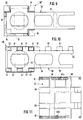
- the variant according to FIG. 8 differs from the design according to FIGS. 5 to 7 in that the angle profile element 14 'is designed with shorter flanks and all three supports 15' and 16 of the corner fitting 10 'are designed with a square cross section. Furthermore, in FIG. 8 the locking plate 30 according to FIG. 8 only consists of an approximately cross-bar-shaped part which corresponds to the head 21 of the locking plate 20 according to FIG. The locking plate 30 can also be inserted into the corner fitting 10 'with two orientations rotated by 90 °.
- the two outer surfaces of the corner fitting 10 ′′ are in turn formed by an angle profile element 14, the flanks of which are as in the exemplary embodiment 5 to 7 provided with cutouts 18, but are somewhat shorter.
- the supports present in the three remaining corners consist of further angle profile pieces 31, each of which has its edge facing the inside of the corner fitting 10 ′′.
- the ends of the angle profile element 14 are welded to the outer flanks of the angle profile pieces 31.
- the locking plate 20 according to FIG. 9 is identical to that in FIG. 5, whereby at one point in FIG. 9 one of the above-mentioned protrusions at 32 that protrudes by 8 mm over the lower surface of the attachment 22 is indicated.
- FIG. 10 shows a central fitting 40, which can be arranged at a middle point of a loading unit located between two corners (cf. 40a, 40b in FIG. 11).
- Such a central fitting can consist of a base plate, a cover plate and four square supports with a square or rectangular cross section similar to the supports 15, 16 according to FIG. 5 or 8.
- the central fitting 40 has a total of six supports 41 with a rectangular cross-section, and the locking plate 50 is provided with two projections 51 on each side in the area in which it engages in the central fitting 40, which protrudes tooth-like between the Support supports 41 of fitting 40.
- the projections 51 can also be provided over the entire length of the locking plate, preferably on both sides, so that the locking plate 50 is in a variety of different length positions can anchor the central fitting 40.
- the center distance between the elongated holes 23, 24 is not an integral multiple of the division between the tooth-like projections 51. This results in a nonius-like fine adjustment possibility with regard to the coupling of the loading unit to a locking element.
- the loading unit 47 shown in FIG. 11 is generally square, two corner fittings 10 and two center fittings 40a, 40b being shown.
- the loading unit 47 is with two Provide pairs of mutually perpendicular forklift channels 48.
- the loading unit 47 By optionally inserting a locking plate in a corner fitting 10 or in a middle fitting 40a, 40b with optional extension of the attachment to the right or left in FIG. 11, the loading unit 47, which can of course still be rotated through 180 °, can be used at almost any position couple a locking element.
- the middle fittings 40a, 40b are drawn in at different locations on the upper and on the lower edge, the fitting 40a being located almost in the middle of the longitudinal edge of the loading unit 47, while the fitting 40b also serves as a lateral limitation of the forklift channel.
- the illustration serves to illustrate the various arrangement options.
- the center fittings 40a or 40b are arranged opposite one another. In order to achieve the greatest possible number of coupling positions, however, it is expedient to offset the center fittings 40 with respect to the central transverse axis of the loading unit 47.
- the locking plate 60 according to FIG. 12 differs from that according to FIG. 10 in that the tooth-like projections 61 are not rectangular but triangular and their flanks run at 45 ° to the longitudinal axis of the locking plate 60. Again, the tooth pitch is chosen so that it is not an integral part of the center distance between the elongated holes 23, 24.
- the corner fitting 70 shown in FIG. 12 has corner supports 71, 72 with inclined contact surfaces in accordance with the triangular tooth-like projections 61 of the locking plate 60.
- the corner fitting 70 is designed symmetrically to the diagonals running through the outer corner of the angle profile element 14 and the inner corner support 72, so that the locking plate 60 extends not only in FIG Lines shown position but also perpendicular to it in the position indicated by dashed lines in the corner fitting 70.
- the inner corner support 72 has the shape of a plate standing in the direction of this diagonal or, as shown, a T-profile piece with a diagonally extending web.
- the locking plate 80 has an even finer tooth pitch than the locking plate 60. This results in the possibility of designing all four supports 91, 92 on the corner fitting 90 such that they face the center of the corner fitting 90 with surfaces running at 45 °. In this way, the locking plate 80 is held symmetrically positively on both sides by the respective supports 91, 92 even when subjected to a tensile force which it tries to pull out of the corner fitting 90.
- FIG. 14 illustrates the locking plate 80 shown in FIG. 13 in connection with a central fitting 100, the side walls of which are each formed by four angle profile pieces 101 arranged in a row and rotated at 45 °.
- the angle profile pieces 101 on one side of the central fitting 100 can be reduced in the upper region 102 in order to allow the locking plate 80 to be inserted obliquely at a low height of the fitting 100.
- FIG. 16 shows the arrangement of the center fitting 100 with the locking plate 80 according to FIG. 14 at the front end of a tank container 107.
Landscapes
- Engineering & Computer Science (AREA)
- Mechanical Engineering (AREA)
- Transportation (AREA)
- Snaps, Bayonet Connections, Set Pins, And Snap Rings (AREA)
- Connection Of Plates (AREA)
Applications Claiming Priority (4)
| Application Number | Priority Date | Filing Date | Title |
|---|---|---|---|
| DE9015095U DE9015095U1 (de) | 1990-11-02 | 1990-11-02 | Ladeeinheit |
| DE9015095U | 1990-11-02 | ||
| DE9017024U DE9017024U1 (de) | 1990-12-17 | 1990-12-17 | Anordnung zum Sichern einer Ladeeinheit |
| DE9017024U | 1990-12-17 |
Publications (2)
| Publication Number | Publication Date |
|---|---|
| EP0483605A2 true EP0483605A2 (fr) | 1992-05-06 |
| EP0483605A3 EP0483605A3 (en) | 1992-05-20 |
Family
ID=25957382
Family Applications (1)
| Application Number | Title | Priority Date | Filing Date |
|---|---|---|---|
| EP19910117686 Withdrawn EP0483605A3 (en) | 1990-11-02 | 1991-10-16 | Arrangement for fixing of a loading unit |
Country Status (4)
| Country | Link |
|---|---|
| EP (1) | EP0483605A3 (fr) |
| JP (1) | JPH05294388A (fr) |
| CN (1) | CN1063647A (fr) |
| AU (1) | AU8670191A (fr) |
Cited By (5)
| Publication number | Priority date | Publication date | Assignee | Title |
|---|---|---|---|---|
| WO1998028208A1 (fr) * | 1996-12-24 | 1998-07-02 | J.S.V. Logistic, S.L. | Nouveau coin d'ancrage pour conteneurs |
| DE19756009A1 (de) * | 1997-12-17 | 1999-07-01 | Fahrzeugtechnik Dessau Gmbh | Tragfahrzeug mit Einrichtungen zum Befestigen von Behältern |
| WO2003018436A1 (fr) * | 2001-08-24 | 2003-03-06 | Minimodal Limited | Dispositif porteur de charge |
| EP1468939A1 (fr) * | 2003-04-16 | 2004-10-20 | Garofoli S.p.A. | Système d'ancrage pour abri ou similaire |
| CN101537921B (zh) * | 2008-03-19 | 2012-08-01 | 中国国际海运集装箱(集团)股份有限公司 | 非标准集装箱 |
Families Citing this family (1)
| Publication number | Priority date | Publication date | Assignee | Title |
|---|---|---|---|---|
| KR101294389B1 (ko) * | 2011-11-08 | 2013-08-08 | 현대중공업 주식회사 | 선박용 컨테이너 래싱장치 |
Family Cites Families (6)
| Publication number | Priority date | Publication date | Assignee | Title |
|---|---|---|---|---|
| US3507224A (en) * | 1967-12-18 | 1970-04-21 | Illinois Railway Equipment Co | Container floor locking mechanism |
| DE7520016U (de) * | 1975-06-24 | 1975-11-06 | Fokker Vfw | Vorrichtung zum Verriegeln von Frachteinheiten |
| DE3501969C2 (de) * | 1985-01-22 | 1987-01-22 | Westerwaelder Eisenwerk Gerhard Gmbh, 5241 Weitefeld | Vorrichtung zum Arretieren eines Containers |
| DE3615354C1 (de) * | 1986-05-06 | 1987-09-17 | Westerwaelder Eisen Gerhard | Anordnung zum Arretieren eines Containers |
| DD283115A5 (de) * | 1989-05-12 | 1990-10-03 | Warnowwerft Warnemuende Veb | Containerabwurfvorrichtung auf schiffen |
| DE8906994U1 (de) * | 1989-06-07 | 1990-10-04 | Westerwälder Eisenwerk Gerhard GmbH, 5241 Weitefeld | Frachtcontainer |
-
1991
- 1991-10-16 EP EP19910117686 patent/EP0483605A3/de not_active Withdrawn
- 1991-10-23 AU AU86701/91A patent/AU8670191A/en not_active Abandoned
- 1991-11-01 JP JP3288124A patent/JPH05294388A/ja active Pending
- 1991-11-02 CN CN 91108390 patent/CN1063647A/zh active Pending
Cited By (7)
| Publication number | Priority date | Publication date | Assignee | Title |
|---|---|---|---|---|
| WO1998028208A1 (fr) * | 1996-12-24 | 1998-07-02 | J.S.V. Logistic, S.L. | Nouveau coin d'ancrage pour conteneurs |
| DE19756009A1 (de) * | 1997-12-17 | 1999-07-01 | Fahrzeugtechnik Dessau Gmbh | Tragfahrzeug mit Einrichtungen zum Befestigen von Behältern |
| DE19756009C2 (de) * | 1997-12-17 | 2000-11-23 | Fahrzeugtechnik Dessau Ag Rail | Tragfahrzeug mit Einrichtungen zum Befestigen von Behältern |
| WO2003018436A1 (fr) * | 2001-08-24 | 2003-03-06 | Minimodal Limited | Dispositif porteur de charge |
| EA005487B1 (ru) * | 2001-08-24 | 2005-02-24 | Минимодал Лимитед | Грузовой контейнер |
| EP1468939A1 (fr) * | 2003-04-16 | 2004-10-20 | Garofoli S.p.A. | Système d'ancrage pour abri ou similaire |
| CN101537921B (zh) * | 2008-03-19 | 2012-08-01 | 中国国际海运集装箱(集团)股份有限公司 | 非标准集装箱 |
Also Published As
| Publication number | Publication date |
|---|---|
| JPH05294388A (ja) | 1993-11-09 |
| AU8670191A (en) | 1992-06-11 |
| EP0483605A3 (en) | 1992-05-20 |
| CN1063647A (zh) | 1992-08-19 |
Similar Documents
| Publication | Publication Date | Title |
|---|---|---|
| EP0097269A2 (fr) | Pièces de coin pour containers | |
| DE3501969C2 (de) | Vorrichtung zum Arretieren eines Containers | |
| EP0519234A1 (fr) | Conteneur pour marchandises | |
| DE3615354C1 (de) | Anordnung zum Arretieren eines Containers | |
| DE9013453U1 (de) | Tankcontainer | |
| DE8807264U1 (de) | Tankcontainer | |
| EP0483605A2 (fr) | Arrangement pour fixer un élément de chargement | |
| DE8906994U1 (de) | Frachtcontainer | |
| DE69008108T2 (de) | Abnehmbares Zwischenstück für die Verbindung und Handhabung von Containern auf Fahrzeugen und entsprechendes Fahrzeug. | |
| EP1465821A1 (fr) | Contenant, notamment conteneur, a ajustage automatique et a verrouillage automatique | |
| DE69121878T2 (de) | Lagergestell | |
| DE3939225C2 (de) | Verfahren und Vorrichtung zum Sichern von Containern auf Schiffen | |
| EP0323623B1 (fr) | Méthode de verrouillage d'au moins deux couches de conteneurs ISO, chacune en nombre impair, pour former une unité de transport ainsi qu'une telle unité de transport | |
| EP0365545B1 (fr) | Agencement de blocage d'unites de chargement | |
| EP0689958B1 (fr) | Dispositif de positionnement pour verrouiller des conteneurs | |
| CH648813A5 (en) | Device for connecting formwork panels stacked one on top of the other | |
| DE2836093C2 (de) | Rungenpalette | |
| DE29815075U1 (de) | Lastensicherungselement für eine Lastensicherungsschiene eines Transportfahrzeugs | |
| EP0215217B1 (fr) | Conteneur de transport | |
| DE29914837U1 (de) | Staustück zur Lagesicherung von Containern an Bord von Schiffen | |
| DE9017024U1 (de) | Anordnung zum Sichern einer Ladeeinheit | |
| EP0323394A1 (fr) | Méthode de verrouillage d'au moins deux conteneurs ISO pour former une unité de transport ainsi que l'unité de transport | |
| DE3201741A1 (de) | Staustrebe zum verzurren von containern o.dgl. | |
| DE29900115U1 (de) | Ringeleinsatz für die Eckstücke von Containern | |
| DE9114038U1 (de) | Anordnung zum Zentrieren und Sichern von Ladeeinheiten auf Fahrzeug-Ladeflächen |
Legal Events
| Date | Code | Title | Description |
|---|---|---|---|
| PUAI | Public reference made under article 153(3) epc to a published international application that has entered the european phase |
Free format text: ORIGINAL CODE: 0009012 |
|
| PUAL | Search report despatched |
Free format text: ORIGINAL CODE: 0009013 |
|
| AK | Designated contracting states |
Kind code of ref document: A2 Designated state(s): BE DE ES FR GB IT NL |
|
| AK | Designated contracting states |
Kind code of ref document: A3 Designated state(s): BE DE ES FR GB IT NL |
|
| 17P | Request for examination filed |
Effective date: 19920521 |
|
| 17Q | First examination report despatched |
Effective date: 19930915 |
|
| STAA | Information on the status of an ep patent application or granted ep patent |
Free format text: STATUS: THE APPLICATION IS DEEMED TO BE WITHDRAWN |
|
| 18D | Application deemed to be withdrawn |
Effective date: 19940514 |