EP0483705A1 - Structure pour un noyau catalytique chauffable électriquement - Google Patents
Structure pour un noyau catalytique chauffable électriquement Download PDFInfo
- Publication number
- EP0483705A1 EP0483705A1 EP91118293A EP91118293A EP0483705A1 EP 0483705 A1 EP0483705 A1 EP 0483705A1 EP 91118293 A EP91118293 A EP 91118293A EP 91118293 A EP91118293 A EP 91118293A EP 0483705 A1 EP0483705 A1 EP 0483705A1
- Authority
- EP
- European Patent Office
- Prior art keywords
- core
- strips
- electrically heatable
- thin metal
- corrugated thin
- Prior art date
- Legal status (The legal status is an assumption and is not a legal conclusion. Google has not performed a legal analysis and makes no representation as to the accuracy of the status listed.)
- Granted
Links
Images
Classifications
-
- F—MECHANICAL ENGINEERING; LIGHTING; HEATING; WEAPONS; BLASTING
- F01—MACHINES OR ENGINES IN GENERAL; ENGINE PLANTS IN GENERAL; STEAM ENGINES
- F01N—GAS-FLOW SILENCERS OR EXHAUST APPARATUS FOR MACHINES OR ENGINES IN GENERAL; GAS-FLOW SILENCERS OR EXHAUST APPARATUS FOR INTERNAL-COMBUSTION ENGINES
- F01N3/00—Exhaust or silencing apparatus having means for purifying, rendering innocuous, or otherwise treating exhaust
- F01N3/08—Exhaust or silencing apparatus having means for purifying, rendering innocuous, or otherwise treating exhaust for rendering innocuous
- F01N3/10—Exhaust or silencing apparatus having means for purifying, rendering innocuous, or otherwise treating exhaust for rendering innocuous by thermal or catalytic conversion of noxious components of exhaust
- F01N3/24—Exhaust or silencing apparatus having means for purifying, rendering innocuous, or otherwise treating exhaust for rendering innocuous by thermal or catalytic conversion of noxious components of exhaust characterised by constructional aspects of converting apparatus
- F01N3/28—Construction of catalytic reactors
- F01N3/2803—Construction of catalytic reactors characterised by structure, by material or by manufacturing of catalyst support
- F01N3/2807—Metal other than sintered metal
- F01N3/281—Metallic honeycomb monoliths made of stacked or rolled sheets, foils or plates
- F01N3/2814—Metallic honeycomb monoliths made of stacked or rolled sheets, foils or plates all sheets, plates or foils being corrugated
-
- F—MECHANICAL ENGINEERING; LIGHTING; HEATING; WEAPONS; BLASTING
- F01—MACHINES OR ENGINES IN GENERAL; ENGINE PLANTS IN GENERAL; STEAM ENGINES
- F01N—GAS-FLOW SILENCERS OR EXHAUST APPARATUS FOR MACHINES OR ENGINES IN GENERAL; GAS-FLOW SILENCERS OR EXHAUST APPARATUS FOR INTERNAL-COMBUSTION ENGINES
- F01N3/00—Exhaust or silencing apparatus having means for purifying, rendering innocuous, or otherwise treating exhaust
- F01N3/08—Exhaust or silencing apparatus having means for purifying, rendering innocuous, or otherwise treating exhaust for rendering innocuous
- F01N3/10—Exhaust or silencing apparatus having means for purifying, rendering innocuous, or otherwise treating exhaust for rendering innocuous by thermal or catalytic conversion of noxious components of exhaust
- F01N3/18—Exhaust or silencing apparatus having means for purifying, rendering innocuous, or otherwise treating exhaust for rendering innocuous by thermal or catalytic conversion of noxious components of exhaust characterised by methods of operation; Control
- F01N3/20—Exhaust or silencing apparatus having means for purifying, rendering innocuous, or otherwise treating exhaust for rendering innocuous by thermal or catalytic conversion of noxious components of exhaust characterised by methods of operation; Control specially adapted for catalytic conversion
- F01N3/2006—Periodically heating or cooling catalytic reactors, e.g. at cold starting or overheating
- F01N3/2013—Periodically heating or cooling catalytic reactors, e.g. at cold starting or overheating using electric or magnetic heating means
- F01N3/2026—Periodically heating or cooling catalytic reactors, e.g. at cold starting or overheating using electric or magnetic heating means directly electrifying the catalyst substrate, i.e. heating the electrically conductive catalyst substrate by joule effect
-
- F—MECHANICAL ENGINEERING; LIGHTING; HEATING; WEAPONS; BLASTING
- F01—MACHINES OR ENGINES IN GENERAL; ENGINE PLANTS IN GENERAL; STEAM ENGINES
- F01N—GAS-FLOW SILENCERS OR EXHAUST APPARATUS FOR MACHINES OR ENGINES IN GENERAL; GAS-FLOW SILENCERS OR EXHAUST APPARATUS FOR INTERNAL-COMBUSTION ENGINES
- F01N2330/00—Structure of catalyst support or particle filter
- F01N2330/02—Metallic plates or honeycombs, e.g. superposed or rolled-up corrugated or otherwise deformed sheet metal
-
- Y—GENERAL TAGGING OF NEW TECHNOLOGICAL DEVELOPMENTS; GENERAL TAGGING OF CROSS-SECTIONAL TECHNOLOGIES SPANNING OVER SEVERAL SECTIONS OF THE IPC; TECHNICAL SUBJECTS COVERED BY FORMER USPC CROSS-REFERENCE ART COLLECTIONS [XRACs] AND DIGESTS
- Y02—TECHNOLOGIES OR APPLICATIONS FOR MITIGATION OR ADAPTATION AGAINST CLIMATE CHANGE
- Y02T—CLIMATE CHANGE MITIGATION TECHNOLOGIES RELATED TO TRANSPORTATION
- Y02T10/00—Road transport of goods or passengers
- Y02T10/10—Internal combustion engine [ICE] based vehicles
- Y02T10/12—Improving ICE efficiencies
Definitions
- This invention relates to an improved structure for and electrically heatable catalytic core and, more particularly, to all electrically heatable catalytic core which resists telescoping in the course of a severe testing regime as described below.
- catalytic converter The purpose of a catalytic converter is to convert pollutant materials in engine or turbine exhaust, e.g., carbon monoxide, unburned hydrocarbons, nitrogen oxides etc., to carbon dioxide, nitrogen and water.
- Conventional catalytic converters utilize a ceramic honeycomb monolith having square or circular straight-through openings or cells with catalyst deposited in the cells, catalyst coated refractory metal oxide beads, e.g., alumina beads, or a corrugated thin metal foil monolith, e.g., ferritic stainless steel foil, having catalyst carried on or supported by the surface.
- the catalyst is normally a noble metal, e.g., platinum, palladium, rhodium, ruthenium, or a mixture of two or more of such metals.
- the catalyst catalyzes a chemical reaction, mainly oxidation, whereby the pollutant is converted to a harmless by-product which then passes through thew exhaust system to the atmosphere.
- conversion is not efficient initially when the exhaust gases are relatively cold.
- the catalyst and the surface of the converter with which the exhaust gases come in contact must be at a minimum temperature, e.g., 390 F for carbon monoxide, 570 F for volatile organic compounds (VOC) and 1000 F for methane or natural gas. Otherwise, conversion to harmless by-products is poor and cold start pollution of the atmosphere is high.
- the catalytic converter is optimally effective. Hence, it is necessary to contact relatively cold exhaust gases with hot catalyst to effect satisfactory conversion at engine start-up. Both compression ignited (diesel) and spark ignited engines have this need.
- an electrically heatable catalytic converter formed of a corrugated thin metal foil monolith which is connected to a voltage source, e.g., a 12 volt or 24 volt automotive battery, and power supplied, preferably before and during start-up, to elevate and maintain the temperature of the catalyst to at least about 650 F.
- a voltage source e.g., a 12 volt or 24 volt automotive battery
- Copending application Serial No. 587,219 filed 24 September 1990 discloses one form of electrically heatable catalytic converter normally subject to telescoping of the core, and provides one means for offsetting the tendency to telescoping of the core in operation and ultimate destruction thereof.
- the present invention provides a different means for offsetting the tendency to telescoping. Because much of the disclosure of Serial No. 587,219 is relevant to the present application, the disclosure of Serial No. 587,219 is incorporated herein by reference thereto.
- the present invention utilizes inter-leaf brazing whereby the leaves are held against telescoping or axial displacement.
- Serial Nos. 524,284 and 587,219 are commonly owned with the present application.
- the electrically heatable catalytic cores are normally spirally wound, or S-wound, corrugated thin metal foil as described in the aforesaid Serial No. 587,219 with the exception that the corrugated thin metal foil strips are not initially washcoated with a refractory metal oxide coating, e.g., an alumina coating, and a catalyst.
- a refractory metal oxide coating e.g., an alumina coating
- the corrugated thin metal cores are subjected to a severe test which they must pass in order to be acceptable. This test involves oscillating (100-200 Hertz and 28 to 60 G) the device in a vertical attitude at high temperature (between 700 and 950 C; 1292 F and 1742 F, respectively) with exhaust gas from a running internal combustion engine being passed through the device. If the wound core device telescopes in the direction of gas flow or breaks up after a predetermined time, e.g., 5 to 200 hours, the device is said to fail the test. Usually, the test
- ferritic stainless steel A suitable formulation for this alloy is described in U.S. Patent 4.414,023 dated 8 November 1983 to Aggens et al.
- a specific ferritic stainless steel useful herein contains 20% chromium, 5% aluminum, and from 0.002% to 0.05% of at least one rare earth metal selected from cerium, lanthanum, neodymium, yttrium and praseodymium, or a mixture of two or more thereof, balance iron and steel making impurities.
- the present invention is an improved structure for an electrically heatable catalytic converter.
- the structure is characterized by corrugated thin metal leaves or strips extending from an electrically conducting central core in alternating relation with thin narrow brazing metal strips.
- the thin narrow brazing metal strips are staggered from side to side of the corrugated thin metal strips or leaves, lying adjacent first one marginal edge of a corrugated thin metal strip, and then adjacent the opposite marginal edge of the next succeeding corrugated thin metal strip.
- the assembly of corrugated thin metal strips and the thin narrow brazing strips is then spirally wound, or S-wound, into a tight core, and a retaining shell placed around the tightly wound core with an intervening wrapping of brazing metal and the whole unit heated to a temperature sufficient to fuse the brazing metal.
- the interleafed brazing strips are fused, and the assembly becomes a rigid unit.
- the the entire unit is dipped into a washcoat of a refractory metal oxide dispersed in water, and the coating baked to tightly adhere the metal oxide, usually gamma alumina, with or without a small amount of ceria, to the metal surface.
- a noble metal catalyst is deposited on the metal oxide surface from and aqueous solution of the noble metal.
- the temperature is then raised to decompose the noble metal containing compound and deposit the catalyst on the surface.
- the catalyst may be dissolved in the aqueous medium of the washcoat before dipping.
- a voltage source usually a 12 or 24 volt automotive battery, is connected across the central conductive bar and the outer retaining shell to provide power to heat the monolith to a minimum of about 650 F in about 10 to about 30 seconds.
- Power in the range of 1500 to 12000 watts may be supplied through a MOSFET power supply system such as described in copending applications Ser. No. 587,219 and Ser. No. 524,284 filed 16 April 1990.
- the resulting catalytically active electrically heatable unit now will resist telescoping during the severe test outlined above. Moreover, the current, instead of flowing through the brazing locations from one leaf to the next, will flow mainly along the length of the corrugated thin metal strip as it provides the shortest path from negative to positive.
- the present invention is in a structure for an electrically heatable catalytic core and a converter containing the same. This core is able to withstand the severe test described above without telescoping.
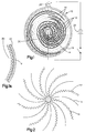
- FIG. 1 there is here shown in cross-section an electrically heatable catalytic core, generally indicated at 10.
- the core 10 is composed of a series of corrugated thin metal strips 12 secured to a central post 14 by any suitable means.
- the preferred means is spot welding.
- the central post 14 may be made up of a group of individual wires or rods with a thin herringbone corrugated metal strip overfolded over each wire. The individual wires with strips welded thereto are gathered together in a bundle and welded at the ends to form the central post 14.
- the strips are reverse folded in the middle thereof to form two portions of equal length, and tack welded along the fold line to a stainless steel or nickel center post 14.
- Folding the herringbone or chevron pattern corrugated thin metal strips prevents the corrugations of one portion from nesting within the corrugations of the adjacent portion.
- the corrugated thin metal strips are from about 1.5" to about 3.5" wide and corrugated by passing between rolls having the corrugation pattern formed therein. Reference may be had to U.S. Patent 4,711,009, supra, for details of the mode of forming corrugated thin metal strips useful herein.
- the corrugated thin metal strips are desirably stainless steel, and preferably a ferritic stainless steel about 0.0015 to 0.0025 inch thick, e.g., 0.0016" thick.
- a particularly useful ferritic stainless steel contains 20% chromium, 5% aluminum, .002% to .05% of at least one rare earth metal selected from cerium, lanthanum, neodymium, yttrium and praseodymium, or a mixture thereof, and the balance iron plus steel making impurities.
- the thin stainless steel strip is corrugated continuously, preferably in a herringbone pattern, or a chevron pattern, and later cut to the desired length.
- the corrugations have an amplitude of from about 0.02" to about 0.25" and a pitch or wavelength of from about 0.03" to about 0.25".
- the chevron or herringbone corrugations desirably have a slope of from 7 degrees to 10 degrees to a line perpendicular to the marginal edges of the thin metal strip, and a pitch of from about 0.75" to about 1.5" from apex to apex.
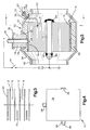
- brazing strips 16 which are 0.375" to 1" wide, are alternately (Figs. 2 and 3) and positioned in staggered relation (Fig. 3). Thereafter, the central post 14 is twisted and the corrugated foil and brazing foil strips spirally wound into a tight cylinder as shown in Fig. 1.
- a layer of brazing foil 22 is desirably interposed between the core 20 and the binding tube 18. This brazing foil layer has an axial length equal to the axial length of the corrugated thin metal strips 12.
- the tube 18 may conveniently be formed of two half shells to be welded together on assembly.
- the brazing foil is rolled to about 0.001" to about 0.003" thick. It is desirably a nickel/chromium/boron/silicon brazing alloy analyzing 75% to 83% nickel with a liquidus temperature of 2100 to 2300 F. Where platinum is to be used as the catalyst metal, phosphorus is avoided in the alloy. Other nickel-containing brazing alloys containing from 7% to 14% chromium, 3% to 4.5% iron, 3.5% to 4.5% silicon, 2% to 3% boron, balance nickel and having liquidus temperatures of above about 2100 F may also be used.
- Fig. 1 and 1a After the core of Fig. 1 and 1a is fully assembled, it is heated to a temperature sufficient to fuse the brazing strips 16 and 22 to the contiguous members. This has the effect of preventing telescoping of the core in the direction of gas flow during a severe high frequency and high temperature test.
- the entire unit is dipped into a slurry of a refractory metal oxide, e.g., an alumina slurry.
- a refractory metal oxide e.g., an alumina slurry.
- the unit (Fig. 4) after wiping off the outer shell is then baked at a temperature sufficient to remove the liquid base (water, principally) from the coating and set to coating on the surface, e.g. about 1000 F.
- the unit (Fig. 4) is then dipped into an aqueous solution of a noble metal catalyst material.
- the porous nature of the gamma alumina coating traps and absorbs the aqueous catalyst-containing solution. Heating of the catalyst treated core to the decomposition temperature of the catalyst-containing compound yields the catalyst metal on the substrate.
- the noble metals useful as catalysts are palladium, platinum, rhodium, ruthenium and mixtures of two or more of such metals. Reference may be had to U.S. Patent 4,711,009 for details of catalytic solutions useful in applying the catalyst to the refractory metal oxide washcoated surface.
- a terminal post 26 is secured to the outside of the outer shell 18 as by welding.
- One of the poles of a voltage source e.g., the positive pole of an automotive vehicle battery, is later secured to the terminal post 26 by a suitable cable.
- the opposite pole of the voltage source e.g., the negative pole of an automotive vehicle battery is later attached to the central post 14 by a suitable cable.
- FIG. 5 shows a completed electrically heatable catalytic converter, generally indicated at 50.
- a steel, preferably stainless steel, housing 52 having adapter end caps 54 and 56 having nipples 58 and 60 which reduce the diameter to the diameter of the exhaust pipe, not shown.
- the unit 10 (See Figs. 1-4) is disposed within the housing 52 which is conveniently formed of half shells welded together at the seam, and the end caps 54 and 56 later welded on.
- a flexible ceramic insulation mat 62 is interposed between the housing 52 and the steel binder shell 18.
- An aperture 64 is provided in the mat 62 to accommodate the positive terminal post 26 and suitable insulation means are provided for traversing the housing 52.
- An aperture 66 is provided through the housing 52 into which is threadedly engaged a bushing 76 which holds an insulating sleeve 74 which in turn surrounds the post 26.
- a metal cap 78 provides a seat for a positive cable clamp, not shown. Current flows to the central post 14 through a transverse bar 80 welded as at 82 to the central post 14 at its midpoint and to the end cap 54 at its extremities.
- one end of the transverse bar 80 may be extended through end cap 54 and threaded to accept a cable connector from the battery.
- the flow of power to the electrically heatable unit 10 is effected by suitable switching means 44.
- suitable switching means 44 Reference may be had to Serial No. 524,284 for the details of a suitable switching means.
- thermocouple 55 extending through the housing 52 with a metal bushing 59.
- the leads terminate in a junction 61 which is embedded in the core 10.
Landscapes
- Chemical & Material Sciences (AREA)
- Engineering & Computer Science (AREA)
- Chemical Kinetics & Catalysis (AREA)
- Health & Medical Sciences (AREA)
- Toxicology (AREA)
- Combustion & Propulsion (AREA)
- Mechanical Engineering (AREA)
- General Engineering & Computer Science (AREA)
- Catalysts (AREA)
- Exhaust Gas After Treatment (AREA)
Applications Claiming Priority (2)
| Application Number | Priority Date | Filing Date | Title |
|---|---|---|---|
| US07/606,130 US5070694A (en) | 1990-10-31 | 1990-10-31 | Structure for electrically heatable catalytic core |
| US606130 | 1996-02-23 |
Publications (2)
| Publication Number | Publication Date |
|---|---|
| EP0483705A1 true EP0483705A1 (fr) | 1992-05-06 |
| EP0483705B1 EP0483705B1 (fr) | 1995-12-27 |
Family
ID=24426674
Family Applications (1)
| Application Number | Title | Priority Date | Filing Date |
|---|---|---|---|
| EP91118293A Expired - Lifetime EP0483705B1 (fr) | 1990-10-31 | 1991-10-26 | Structure pour un noyau catalytique chauffable électriquement |
Country Status (6)
| Country | Link |
|---|---|
| US (1) | US5070694A (fr) |
| EP (1) | EP0483705B1 (fr) |
| JP (1) | JPH04284852A (fr) |
| AT (1) | ATE132230T1 (fr) |
| CA (1) | CA2050733A1 (fr) |
| DE (1) | DE69115848T2 (fr) |
Cited By (2)
| Publication number | Priority date | Publication date | Assignee | Title |
|---|---|---|---|---|
| EP0581784B1 (fr) * | 1991-04-10 | 1999-06-02 | Emitec Gesellschaft für Emissionstechnologie mbH | Corps en nid d'abeille pouvant etre chauffe electriquement |
| CN110206622A (zh) * | 2019-06-04 | 2019-09-06 | 亿达天地环保技术股份有限公司 | 双层套管结构电加热废气处理装置 |
Families Citing this family (75)
| Publication number | Priority date | Publication date | Assignee | Title |
|---|---|---|---|---|
| JPH04136412A (ja) * | 1990-09-28 | 1992-05-11 | Nissan Motor Co Ltd | ハニカム触媒コンバータの加熱装置 |
| US5427601A (en) * | 1990-11-29 | 1995-06-27 | Ngk Insulators, Ltd. | Sintered metal bodies and manufacturing method therefor |
| JP2990797B2 (ja) * | 1990-11-30 | 1999-12-13 | 株式会社デンソー | ハニカムヒータ |
| US5174968A (en) * | 1990-12-12 | 1992-12-29 | W. R. Grace & Co.-Conn. | Structure for electrically heatable catalytic core |
| US5170624A (en) * | 1991-04-05 | 1992-12-15 | W. R. Grace & Co.-Conn. | Composite catalytic converter |
| DE4112354A1 (de) * | 1991-04-16 | 1992-10-22 | Behr Gmbh & Co | Vorrichtung zum katalytischen entgiften von abgasen |
| US5204067A (en) * | 1991-07-11 | 1993-04-20 | Schwaebische Huettenwerke Gmbh | Filter |
| DE4129894A1 (de) * | 1991-09-09 | 1993-03-11 | Emitec Emissionstechnologie | Elektrische isolierung von strukturen in einem wabenkoerper, insbesondere einem elektrisch beheizbaren katalysator-traegerkoerper |
| US5238650A (en) * | 1991-09-13 | 1993-08-24 | W. R. Grace & Co.-Conn. | Electrode feed through |
| JP3000750B2 (ja) * | 1991-09-20 | 2000-01-17 | 株式会社デンソー | 自己発熱型フィルタ |
| US5271906A (en) * | 1991-10-28 | 1993-12-21 | Toyota Jidosha Kabushiki Kaisha | Exhaust emission control apparatus using catalytic converter with hydrocarbon absorbent |
| US5140812A (en) * | 1991-11-05 | 1992-08-25 | W. R. Grace & Co.-Conn. | Core for an electrically heatable catalytic converter |
| DE4137105A1 (de) * | 1991-11-12 | 1993-05-13 | Schwaebische Huettenwerke Gmbh | Anordnung eines katalysators fuer die abgase eines verbrennungsmotors |
| US5554342A (en) * | 1991-12-20 | 1996-09-10 | Toyota Jidosha Kabushiki Kaisha | Electrical heating type catalytic device |
| JP3278184B2 (ja) | 1991-12-20 | 2002-04-30 | トヨタ自動車株式会社 | 通電加熱式触媒装置 |
| US5232671A (en) * | 1992-01-27 | 1993-08-03 | W. R. Grace & Co.-Conn. | Core for a catalytic converter |
| FR2687431B1 (fr) * | 1992-02-14 | 1995-07-13 | Inst Francais Du Petrole | Tubulure d'echappement a paroi catalytique pour moteurs a combustion interne. |
| CA2083742A1 (fr) * | 1992-02-19 | 1993-08-20 | David T. Sheller | Element central pour convertisseur catalytique |
| FR2688540B1 (fr) * | 1992-03-10 | 1995-07-21 | Inst Francais Du Petrole | Ligne d'echappement avec catalyseur pour moteurs a combustion interne a deux temps et procede de traitement de gaz d'echappement comportant une telle ligne. |
| DE69301547T2 (de) * | 1992-04-20 | 1996-09-19 | Nippon Steel Corp | Elektrisch heizbarer katalytischer Umwandler |
| US5246672A (en) * | 1992-04-23 | 1993-09-21 | Williams International Corporation | Spiral wound microlith catalyst bed |
| US5252299A (en) * | 1992-05-28 | 1993-10-12 | Retallick William B | Catalytic air cleaner |
| US5288470A (en) * | 1992-10-02 | 1994-02-22 | W. R. Grace & Co.-Conn. | Metal substrate having an insulating barrier |
| US5582805A (en) * | 1992-12-21 | 1996-12-10 | Toyota Jidosha Kabushiki Kaisha | Electrically heated catalytic apparatus |
| US5866230A (en) * | 1993-01-11 | 1999-02-02 | Emitec Gesellschaft Fuer Emissionstechnologie Gmbh | Extruded honeycomb body of ceramic and/or metallic material with increased flexibility |
| US5546746A (en) * | 1993-02-04 | 1996-08-20 | W. R. Grace & Co.-Conn. | Core element useful in a combined electrically heatable and light-off converter |
| WO1994026455A1 (fr) * | 1993-05-12 | 1994-11-24 | Nippon Steel Corporation | Procede de soudage d'alliage thermoresistant a surface recouverte d'une couche mince d'oxyde isolant, support metallique d'epuration de gaz d'echappement de type prechauffe et son procede de production |
| US5422083A (en) * | 1993-06-29 | 1995-06-06 | W. R. Grace & Co.-Conn. | Reinforced converter body |
| US5487869A (en) * | 1993-09-24 | 1996-01-30 | Retallick; William B. | Air cleaner capable of catalytic regeneration |
| JP3277655B2 (ja) * | 1993-12-21 | 2002-04-22 | トヨタ自動車株式会社 | 電気加熱式触媒装置 |
| JPH07238825A (ja) * | 1994-02-25 | 1995-09-12 | Toyota Motor Corp | 電気ヒータ付触媒装置 |
| US5891402A (en) * | 1994-03-02 | 1999-04-06 | W. L. Gore & Associates, Inc. | Catalyst retaining apparatus and use in an ozone filter |
| US5431886A (en) * | 1994-04-08 | 1995-07-11 | W. R. Grace & Co.-Conn. | Combined electrically heatable converter |
| US5573731A (en) * | 1994-05-30 | 1996-11-12 | Toyota Jidosha Kabushiki Kaisha | Electrically heated catalytic converter for an engine |
| JP3305505B2 (ja) * | 1994-07-29 | 2002-07-22 | 日本碍子株式会社 | 電極構造 |
| JPH0871430A (ja) * | 1994-09-07 | 1996-03-19 | Nippon Soken Inc | 通電加熱式触媒装置 |
| US5632961A (en) * | 1995-01-10 | 1997-05-27 | W. R. Grace & Co.-Conn. | Reinforcing web for a multicellular converter |
| JPH08218846A (ja) * | 1995-02-17 | 1996-08-27 | Nippon Soken Inc | 内燃機関の排気浄化装置用電気ヒータ |
| US5786031A (en) * | 1995-06-07 | 1998-07-28 | Engelhard Corporation | Barrier for a metal substrate |
| AU6488196A (en) * | 1995-07-12 | 1997-02-10 | Engelhard Corporation | Structure for converter body |
| US5820835A (en) * | 1995-07-12 | 1998-10-13 | Engelhard Corporation | Assembly and method for making catalytic converter structure |
| US5846495A (en) * | 1995-07-12 | 1998-12-08 | Engelhard Corporation | Structure for converter body |
| US5851495A (en) * | 1995-10-02 | 1998-12-22 | Toyota Jidosha Kabushiki Kaisha | Electrically heated catalytic converter for an engine |
| AU1685397A (en) * | 1995-12-22 | 1997-07-17 | W.R. Grace & Co. | Assembly and method for making catalytic converter structures |
| US6216687B1 (en) | 1996-03-22 | 2001-04-17 | The Majestic Products Company | Unvented heating appliance having system for reducing undesirable combustion products |
| US6060173A (en) * | 1996-04-17 | 2000-05-09 | Englehard Corporation | Metal honeycomb body |
| US6109018A (en) * | 1996-07-26 | 2000-08-29 | Catalytica, Inc. | Electrically-heated combustion catalyst structure and method for start-up of a gas turbine using same |
| EP1208906B1 (fr) * | 2000-11-28 | 2006-04-05 | Haldor Topsoe A/S | Réacteur pour exécuter des réactions non-adiabatiques |
| US7320778B2 (en) * | 2004-07-21 | 2008-01-22 | Catacel Corp. | High-performance catalyst support |
| US20060177358A1 (en) * | 2005-02-07 | 2006-08-10 | Tzong-Yih Lee | Active catalytic converter |
| WO2011114451A1 (fr) * | 2010-03-17 | 2011-09-22 | トヨタ自動車株式会社 | Dispositif de commande de véhicule |
| JP5088443B2 (ja) * | 2010-03-29 | 2012-12-05 | トヨタ自動車株式会社 | 触媒コンバータ装置 |
| WO2011125177A1 (fr) * | 2010-04-06 | 2011-10-13 | トヨタ自動車株式会社 | Convertisseur catalytique électriquement chauffé |
| JP5472468B2 (ja) * | 2010-07-30 | 2014-04-16 | トヨタ自動車株式会社 | 電気加熱式触媒 |
| WO2012025993A1 (fr) | 2010-08-24 | 2012-03-01 | トヨタ自動車株式会社 | Catalyseur chauffé électriquement |
| US9121322B2 (en) * | 2010-08-31 | 2015-09-01 | Toyota Jidosha Kabushiki Kaisha | Electrically heated catalyst |
| US8911674B2 (en) * | 2010-09-10 | 2014-12-16 | Toyota Jidosha Kabushiki Kaisha | Electrically heated catalyst |
| WO2012032652A1 (fr) | 2010-09-10 | 2012-03-15 | トヨタ自動車株式会社 | Catalyseur électriquement chauffé |
| CN102596409B (zh) * | 2010-10-27 | 2014-05-14 | 丰田自动车株式会社 | 电加热式催化器 |
| WO2012093481A1 (fr) | 2011-01-06 | 2012-07-12 | イビデン株式会社 | Appareil de traitement de gaz d'échappement |
| JP5626371B2 (ja) * | 2011-02-08 | 2014-11-19 | トヨタ自動車株式会社 | 電気加熱式触媒 |
| US8961884B2 (en) * | 2011-02-14 | 2015-02-24 | Toyota Jidosha Kabushiki Kaisha | Electric heating catalyst |
| US20130312394A1 (en) * | 2011-02-16 | 2013-11-28 | Toyota Jidosha Kabushiki Kaisha | Electric heating catalyst |
| WO2012120669A1 (fr) * | 2011-03-09 | 2012-09-13 | トヨタ自動車株式会社 | Catalyseur chauffé électriquement |
| DE102011110664A1 (de) * | 2011-08-19 | 2013-02-21 | Emitec Gesellschaft Für Emissionstechnologie Mbh | Vorrichtung zur Behandlung von Abgasen |
| US9109490B2 (en) * | 2011-09-06 | 2015-08-18 | Toyota Jidosha Kabushiki Kaisha | Electric heating catalyst |
| US9181833B2 (en) * | 2011-10-18 | 2015-11-10 | Toyota Jidosha Kabushiki Kaisha | Electrically heated catalyst |
| JP6408865B2 (ja) * | 2014-10-28 | 2018-10-17 | イビデン株式会社 | 電気加熱式触媒コンバータ |
| US10995998B2 (en) * | 2015-07-30 | 2021-05-04 | Senior Uk Limited | Finned coaxial cooler |
| JP6263319B2 (ja) * | 2015-10-06 | 2018-01-17 | 新日鉄住金マテリアルズ株式会社 | 触媒担持用基材及び触媒担体 |
| CA3025491A1 (fr) * | 2016-05-23 | 2017-11-30 | Johnson Matthey Public Limited Company | Agencement de centre extensible |
| FR3079264B1 (fr) * | 2018-03-20 | 2020-03-13 | Faurecia Systemes D'echappement | Organe de purification de gaz d'echappement chauffant et dispositif de purification comprenant un tel organe de purification |
| DE102019110359A1 (de) * | 2019-04-18 | 2020-10-22 | Faurecia Emissions Control Technologies, Germany Gmbh | Abgasbehandlungseinrichtung und Fahrzeug |
| DE102021211213B3 (de) * | 2021-10-05 | 2023-01-26 | Vitesco Technologies GmbH | Elektrisch beheizbarer Wabenkörper mit Welllagen unterschiedlicher Zelldichte |
| US20240401846A1 (en) * | 2023-05-31 | 2024-12-05 | Proof Energy Inc. | Catalytic heating systems with self-heated catalytic reactors and methods of operating thereof |
Citations (6)
| Publication number | Priority date | Publication date | Assignee | Title |
|---|---|---|---|---|
| US3770389A (en) * | 1971-11-11 | 1973-11-06 | Ford Motor Co | Catalytic converter with electrically resistive catalyst support |
| DE8812924U1 (de) * | 1988-10-14 | 1988-12-01 | Emitec Gesellschaft für Emissionstechnologie mbH, 53797 Lohmar | Trägerkörper für einen katalytischen Reaktor zur Abgasreinigung |
| EP0322566A1 (fr) * | 1987-12-23 | 1989-07-05 | Emitec Gesellschaft für Emissionstechnologie mbH | Procédé et dispositif pour la fabrication d'un support métallique pour réacteurs catalytiques |
| EP0245736B1 (fr) * | 1986-05-12 | 1989-08-23 | Siemens Aktiengesellschaft | Support métallique pour catalyseurs dont les tôles sont courbées en forme de développante |
| EP0351841A1 (fr) * | 1988-07-22 | 1990-01-24 | Nippon Yakin Kogyo Kabushiki Kaisha | Support de catalyseur pour convertisseurs catalytiques |
| US4928485A (en) * | 1989-06-06 | 1990-05-29 | W. R. Grace & Co.,-Conn. | Metallic core member for catalytic converter and catalytic converter containing same |
Family Cites Families (14)
| Publication number | Priority date | Publication date | Assignee | Title |
|---|---|---|---|---|
| DE563757C (fr) * | 1929-08-12 | |||
| FR2113249A5 (fr) * | 1970-11-03 | 1972-06-23 | Getters Spa | |
| US3795524A (en) * | 1971-03-01 | 1974-03-05 | Minnesota Mining & Mfg | Aluminum borate and aluminum borosilicate articles |
| US3768982A (en) * | 1971-06-22 | 1973-10-30 | Ford Motor Co | Catalytic converter with electrically preheated catalyst |
| CA1102706A (fr) * | 1977-05-06 | 1981-06-09 | Rainer Scholz | Catalyseur homogene en metal pour eliminer les composants toxiques en presence dans les gaz d'echappement des moteurs a combustion interne |
| DE2924592C2 (de) * | 1979-06-19 | 1983-05-26 | Süddeutsche Kühlerfabrik Julius Fr. Behr GmbH & Co KG, 7000 Stuttgart | Verfahren zum Herstellen einer Trägermatrix für einen katalytischen Reaktor zur Abgasreinigung bei Brennkraftmaschinen von Kraftfahrzeugen |
| US4414023A (en) * | 1982-04-12 | 1983-11-08 | Allegheny Ludlum Steel Corporation | Iron-chromium-aluminum alloy and article and method therefor |
| US4598063A (en) * | 1985-08-09 | 1986-07-01 | Retallick William B | Spiral catalyst support and method of making it |
| US4711009A (en) * | 1986-02-18 | 1987-12-08 | W. R. Grace & Co. | Process for making metal substrate catalytic converter cores |
| DE3634235C1 (de) * | 1986-10-08 | 1988-03-31 | Sueddeutsche Kuehler Behr | Matrix fuer einen katalytischen Reaktor zur Abgasreinigung |
| US4976929A (en) * | 1988-05-20 | 1990-12-11 | W. R. Grace & Co.-Conn. | Electrically heated catalytic converter |
| US4810588A (en) * | 1988-05-24 | 1989-03-07 | W. R. Grace & Co.-Conn. | Nonnesting, straight corrugation metal foil and method for making same |
| DE8910470U1 (de) * | 1989-09-01 | 1991-01-03 | Lucas Industries P.L.C., Birmingham, West Midlands | Pneumatisch-hydraulischer Druckerzeuger, insbesondere für Fahrzeugbremsanlagen |
| DE8910471U1 (de) * | 1989-09-01 | 1991-01-10 | Nixdorf Computer Ag, 4790 Paderborn | Halterungsvorrichtung für ein elektrisches Bauteil |
-
1990
- 1990-10-31 US US07/606,130 patent/US5070694A/en not_active Expired - Fee Related
-
1991
- 1991-09-05 CA CA002050733A patent/CA2050733A1/fr not_active Abandoned
- 1991-10-15 JP JP3293863A patent/JPH04284852A/ja active Pending
- 1991-10-26 AT AT91118293T patent/ATE132230T1/de not_active IP Right Cessation
- 1991-10-26 DE DE69115848T patent/DE69115848T2/de not_active Expired - Fee Related
- 1991-10-26 EP EP91118293A patent/EP0483705B1/fr not_active Expired - Lifetime
Patent Citations (6)
| Publication number | Priority date | Publication date | Assignee | Title |
|---|---|---|---|---|
| US3770389A (en) * | 1971-11-11 | 1973-11-06 | Ford Motor Co | Catalytic converter with electrically resistive catalyst support |
| EP0245736B1 (fr) * | 1986-05-12 | 1989-08-23 | Siemens Aktiengesellschaft | Support métallique pour catalyseurs dont les tôles sont courbées en forme de développante |
| EP0322566A1 (fr) * | 1987-12-23 | 1989-07-05 | Emitec Gesellschaft für Emissionstechnologie mbH | Procédé et dispositif pour la fabrication d'un support métallique pour réacteurs catalytiques |
| EP0351841A1 (fr) * | 1988-07-22 | 1990-01-24 | Nippon Yakin Kogyo Kabushiki Kaisha | Support de catalyseur pour convertisseurs catalytiques |
| DE8812924U1 (de) * | 1988-10-14 | 1988-12-01 | Emitec Gesellschaft für Emissionstechnologie mbH, 53797 Lohmar | Trägerkörper für einen katalytischen Reaktor zur Abgasreinigung |
| US4928485A (en) * | 1989-06-06 | 1990-05-29 | W. R. Grace & Co.,-Conn. | Metallic core member for catalytic converter and catalytic converter containing same |
Cited By (3)
| Publication number | Priority date | Publication date | Assignee | Title |
|---|---|---|---|---|
| EP0581784B1 (fr) * | 1991-04-10 | 1999-06-02 | Emitec Gesellschaft für Emissionstechnologie mbH | Corps en nid d'abeille pouvant etre chauffe electriquement |
| CN110206622A (zh) * | 2019-06-04 | 2019-09-06 | 亿达天地环保技术股份有限公司 | 双层套管结构电加热废气处理装置 |
| CN110206622B (zh) * | 2019-06-04 | 2021-07-27 | 亿达天地环保技术股份有限公司 | 双层套管结构电加热废气处理装置 |
Also Published As
| Publication number | Publication date |
|---|---|
| DE69115848T2 (de) | 1996-05-30 |
| CA2050733A1 (fr) | 1992-05-01 |
| JPH04284852A (ja) | 1992-10-09 |
| EP0483705B1 (fr) | 1995-12-27 |
| ATE132230T1 (de) | 1996-01-15 |
| DE69115848D1 (de) | 1996-02-08 |
| US5070694A (en) | 1991-12-10 |
Similar Documents
| Publication | Publication Date | Title |
|---|---|---|
| US5070694A (en) | Structure for electrically heatable catalytic core | |
| US5174968A (en) | Structure for electrically heatable catalytic core | |
| US5177961A (en) | Upstream collimator for electrically heatable catalytic converter | |
| US5140812A (en) | Core for an electrically heatable catalytic converter | |
| US5232671A (en) | Core for a catalytic converter | |
| US5140813A (en) | Composite catalytic converter | |
| US5170624A (en) | Composite catalytic converter | |
| EP0635627B1 (fr) | Convertisseur combiné chauffable électriquement | |
| US5149508A (en) | Parallel path catalytic converter | |
| US5456890A (en) | Combined electrically heatable and light-off converter | |
| JPH0372953A (ja) | 触媒コンバーターのための金属コア部材及びそれを含有する触媒コンバーター | |
| US5240682A (en) | Reinforced corrugated thin metal foil strip useful in a catalytic converter core, a catalytic converter core containing said strip and an electrically heatable catalytic converter containing said core | |
| US5384099A (en) | Core element for catalytic converter | |
| US5272876A (en) | Core element for catalytic converter | |
| US5628928A (en) | Method for reducing the potential difference in an electrically heatable converter by connecting the strip heater to corrugated strip with an electrical conductor | |
| US5546746A (en) | Core element useful in a combined electrically heatable and light-off converter | |
| EP0569109A1 (fr) | Elément de noyau pour catalyseur | |
| US5308591A (en) | Core body for catalytic converter | |
| US5512251A (en) | Combined electrically heatable converter body | |
| EP0503445A1 (fr) | Insert catalytique chauffable électriquement | |
| EP0677649B1 (fr) | Elément de noyau pour convertisseur combiné chauffable électriquement et à auto-amorçage | |
| WO1995016110A1 (fr) | Convertisseur combine ameliore avec section a chauffage electrique et section passive | |
| JPH02277916A (ja) | 並列パス触媒コンバーター |
Legal Events
| Date | Code | Title | Description |
|---|---|---|---|
| PUAI | Public reference made under article 153(3) epc to a published international application that has entered the european phase |
Free format text: ORIGINAL CODE: 0009012 |
|
| AK | Designated contracting states |
Kind code of ref document: A1 Designated state(s): AT BE CH DE DK ES FR GB GR IT LI LU NL SE |
|
| 17P | Request for examination filed |
Effective date: 19920508 |
|
| 17Q | First examination report despatched |
Effective date: 19930719 |
|
| GRAA | (expected) grant |
Free format text: ORIGINAL CODE: 0009210 |
|
| AK | Designated contracting states |
Kind code of ref document: B1 Designated state(s): AT BE CH DE DK ES FR GB GR IT LI LU NL SE |
|
| PG25 | Lapsed in a contracting state [announced via postgrant information from national office to epo] |
Ref country code: IT Free format text: LAPSE BECAUSE OF FAILURE TO SUBMIT A TRANSLATION OF THE DESCRIPTION OR TO PAY THE FEE WITHIN THE PRE;WARNING: LAPSES OF ITALIAN PATENTS WITH EFFECTIVE DATE BEFORE 2007 MAY HAVE OCCURRED AT ANY TIME BEFORE 2007. THE CORRECT EFFECTIVE DATE MAY BE DIFFERENT FROM THE ONE RECORDED.SCRIBED TIME-LIMIT Effective date: 19951227 Ref country code: DK Effective date: 19951227 Ref country code: ES Free format text: THE PATENT HAS BEEN ANNULLED BY A DECISION OF A NATIONAL AUTHORITY Effective date: 19951227 Ref country code: GR Free format text: LAPSE BECAUSE OF FAILURE TO SUBMIT A TRANSLATION OF THE DESCRIPTION OR TO PAY THE FEE WITHIN THE PRESCRIBED TIME-LIMIT Effective date: 19951227 Ref country code: FR Effective date: 19951227 Ref country code: AT Effective date: 19951227 Ref country code: BE Effective date: 19951227 Ref country code: LI Effective date: 19951227 Ref country code: NL Free format text: LAPSE BECAUSE OF FAILURE TO SUBMIT A TRANSLATION OF THE DESCRIPTION OR TO PAY THE FEE WITHIN THE PRESCRIBED TIME-LIMIT Effective date: 19951227 Ref country code: CH Effective date: 19951227 |
|
| REF | Corresponds to: |
Ref document number: 132230 Country of ref document: AT Date of ref document: 19960115 Kind code of ref document: T |
|
| REF | Corresponds to: |
Ref document number: 69115848 Country of ref document: DE Date of ref document: 19960208 |
|
| PG25 | Lapsed in a contracting state [announced via postgrant information from national office to epo] |
Ref country code: SE Effective date: 19960327 |
|
| EN | Fr: translation not filed | ||
| NLV1 | Nl: lapsed or annulled due to failure to fulfill the requirements of art. 29p and 29m of the patents act | ||
| PGFP | Annual fee paid to national office [announced via postgrant information from national office to epo] |
Ref country code: GB Payment date: 19961017 Year of fee payment: 6 |
|
| PG25 | Lapsed in a contracting state [announced via postgrant information from national office to epo] |
Ref country code: LU Free format text: LAPSE BECAUSE OF NON-PAYMENT OF DUE FEES Effective date: 19961031 |
|
| PLBE | No opposition filed within time limit |
Free format text: ORIGINAL CODE: 0009261 |
|
| STAA | Information on the status of an ep patent application or granted ep patent |
Free format text: STATUS: NO OPPOSITION FILED WITHIN TIME LIMIT |
|
| PGFP | Annual fee paid to national office [announced via postgrant information from national office to epo] |
Ref country code: DE Payment date: 19961104 Year of fee payment: 6 |
|
| 26N | No opposition filed | ||
| PG25 | Lapsed in a contracting state [announced via postgrant information from national office to epo] |
Ref country code: GB Free format text: LAPSE BECAUSE OF NON-PAYMENT OF DUE FEES Effective date: 19971026 |
|
| GBPC | Gb: european patent ceased through non-payment of renewal fee |
Effective date: 19971026 |
|
| PG25 | Lapsed in a contracting state [announced via postgrant information from national office to epo] |
Ref country code: DE Free format text: LAPSE BECAUSE OF NON-PAYMENT OF DUE FEES Effective date: 19980701 |