EP0483728A1 - Verfahren und Vorrichtung zum Herstellen von Textilschläuchen - Google Patents
Verfahren und Vorrichtung zum Herstellen von Textilschläuchen Download PDFInfo
- Publication number
- EP0483728A1 EP0483728A1 EP91118358A EP91118358A EP0483728A1 EP 0483728 A1 EP0483728 A1 EP 0483728A1 EP 91118358 A EP91118358 A EP 91118358A EP 91118358 A EP91118358 A EP 91118358A EP 0483728 A1 EP0483728 A1 EP 0483728A1
- Authority
- EP
- European Patent Office
- Prior art keywords
- band
- length
- predetermined
- dragging
- order
- Prior art date
- Legal status (The legal status is an assumption and is not a legal conclusion. Google has not performed a legal analysis and makes no representation as to the accuracy of the status listed.)
- Withdrawn
Links
- 239000004753 textile Substances 0.000 title claims description 57
- 238000000034 method Methods 0.000 title claims description 18
- 238000011144 upstream manufacturing Methods 0.000 claims abstract description 19
- 238000005520 cutting process Methods 0.000 claims description 80
- 239000004744 fabric Substances 0.000 claims description 27
- 238000009958 sewing Methods 0.000 claims description 18
- 238000005304 joining Methods 0.000 claims description 16
- 238000004519 manufacturing process Methods 0.000 claims description 14
- 238000001514 detection method Methods 0.000 claims description 13
- 238000013459 approach Methods 0.000 claims 1
- 230000015572 biosynthetic process Effects 0.000 description 4
- 238000006073 displacement reaction Methods 0.000 description 3
- 239000011159 matrix material Substances 0.000 description 3
- 238000005452 bending Methods 0.000 description 1
- 230000007547 defect Effects 0.000 description 1
- 238000010586 diagram Methods 0.000 description 1
- 239000013536 elastomeric material Substances 0.000 description 1
- 239000011152 fibreglass Substances 0.000 description 1
- 238000000465 moulding Methods 0.000 description 1
- 239000003973 paint Substances 0.000 description 1
- 238000003860 storage Methods 0.000 description 1
- 238000004073 vulcanization Methods 0.000 description 1
Images

Classifications
-
- B—PERFORMING OPERATIONS; TRANSPORTING
- B65—CONVEYING; PACKING; STORING; HANDLING THIN OR FILAMENTARY MATERIAL
- B65H—HANDLING THIN OR FILAMENTARY MATERIAL, e.g. SHEETS, WEBS, CABLES
- B65H35/00—Delivering articles from cutting or line-perforating machines; Article or web delivery apparatus incorporating cutting or line-perforating devices, e.g. adhesive tape dispensers
- B65H35/04—Delivering articles from cutting or line-perforating machines; Article or web delivery apparatus incorporating cutting or line-perforating devices, e.g. adhesive tape dispensers from or with transverse cutters or perforators
- B65H35/06—Delivering articles from cutting or line-perforating machines; Article or web delivery apparatus incorporating cutting or line-perforating devices, e.g. adhesive tape dispensers from or with transverse cutters or perforators from or with blade, e.g. shear-blade, cutters or perforators
-
- B—PERFORMING OPERATIONS; TRANSPORTING
- B29—WORKING OF PLASTICS; WORKING OF SUBSTANCES IN A PLASTIC STATE IN GENERAL
- B29D—PRODUCING PARTICULAR ARTICLES FROM PLASTICS OR FROM SUBSTANCES IN A PLASTIC STATE
- B29D29/00—Producing belts or bands
-
- B—PERFORMING OPERATIONS; TRANSPORTING
- B29—WORKING OF PLASTICS; WORKING OF SUBSTANCES IN A PLASTIC STATE IN GENERAL
- B29D—PRODUCING PARTICULAR ARTICLES FROM PLASTICS OR FROM SUBSTANCES IN A PLASTIC STATE
- B29D29/00—Producing belts or bands
- B29D29/08—Toothed driving belts
-
- B—PERFORMING OPERATIONS; TRANSPORTING
- B29—WORKING OF PLASTICS; WORKING OF SUBSTANCES IN A PLASTIC STATE IN GENERAL
- B29D—PRODUCING PARTICULAR ARTICLES FROM PLASTICS OR FROM SUBSTANCES IN A PLASTIC STATE
- B29D30/00—Producing pneumatic or solid tyres or parts thereof
- B29D30/06—Pneumatic tyres or parts thereof (e.g. produced by casting, moulding, compression moulding, injection moulding, centrifugal casting)
- B29D30/38—Textile inserts, e.g. cord or canvas layers, for tyres; Treatment of inserts prior to building the tyre
- B29D30/42—Endless textile bands without bead-rings
-
- B—PERFORMING OPERATIONS; TRANSPORTING
- B29—WORKING OF PLASTICS; WORKING OF SUBSTANCES IN A PLASTIC STATE IN GENERAL
- B29C—SHAPING OR JOINING OF PLASTICS; SHAPING OF MATERIAL IN A PLASTIC STATE, NOT OTHERWISE PROVIDED FOR; AFTER-TREATMENT OF THE SHAPED PRODUCTS, e.g. REPAIRING
- B29C2793/00—Shaping techniques involving a cutting or machining operation
- B29C2793/0081—Shaping techniques involving a cutting or machining operation before shaping
Definitions
- the present invention relates to a process and an apparatus to make textile sleeves.
- the invention has been conceived for the purpose of producing sleeves to be used in the manufacture of driving belts of the toothed type, to which particular reference will be made in the course of the present description.
- the fabric continuously fed is first transversely cut so as to obtain a number of cloths of predetermined sizes that are subsequently joined together one after the other by means of seams along respective edges perpendicular to the cut direction.
- each length is then disposed close to each other and sewn together by a closing seam so as to achieve the desired textile sleeve.
- each finished sleeve will have different transverse seams, represented by the final closing seam and by at least one of the cloth-joining seams respectively.
- each sleeve has a single connecting seam in addition to the closing seam.
- the distance between these two seams varies at random from one sleeve to another depending upon the position in which the connecting seam is when the cutting operations for the achievement of a length are carried out.
- the minimum distance between the seams on the circumferential extension of the sleeve should not be lower than a predetermined value generally on the order of 8 to 10 cm.
- the object of the present invention is to provide a process and an apparatus to make textile sleeves starting from a continuous fabric in a completely automatic and very accurate manner, which textile sleeves have, particularly, transverse seams spaced apart from each other beyond a minimum predetermined extent.
- the apparatus according to the invention is capable of ensuring the production of sleeves the seams of which are spaced apart from each other beyond a minimum predetermined extent, by automatically adapting itself to the accomplishment of sleeves of different sizes so as to reduce as much as possible the production of scraps.
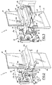
- an apparatus to automatically produce textile sleeves having transverse seams spaced apart from each other beyond a predetermined minimum extent in accordance with the present invention has been generally identified by reference numeral 1.
- Apparatus 1 is mounted to a machine generally denoted by 2, adapted to automatically make textile sleeves starting from a continous fabric.
- the automatic machine 2 essentially comprises a supply station 3 from which a continuous rubberized fabric 4 previously wound in the form of a roll 4a is drawn, upon the action of one gripping member 5 suitably disposing it on one cutting station 6.
- One cutting member 6a associated with the cutting station 6 transversely cuts the fabric 4 thereby obtaining a number of pieces or cloths 7 which, upon the action of a second gripping member 8, are moved forward, parallelly to the direction of the executed cut, on a sliding surface 9 for engagement at a first connecting station 10.
- the textile band 12 is moved forward on a suspended surface 13, by a third gripping member 14.
- the third gripping member 14 acts so that, at each operating cycle of the connecting station 10, the textile band 12 is arranged so as to have an end portion 12c thereof suitably projecting from the front edge 13a of the suspended surface 13.
- the end portion 12c can be folded under said front edge 13a upon the action of a thrust bar 15, in order to be sewn together with the end edge of the coming cloth 7.
- the band 12 moving away from the first connecting station 10 is engaged, after passing through a known and conventional storage device consisting of rollers 16, in a second cutting station 17 comprised, as more clearly shown in Figs. 2 and 3, of a respective cutting member 18 operatively mounted to a guide 19 fastened to the machine 2 framework and movable at right angles to the longitudinal extension of the band for cutting it according to lengths 20 of the desired longitudinal extension.
- One or more connecting seams previously made for consecutively joining the cloths 7 will be present on each length 20.
- the length 20 has only one connecting seam 12a which is therefore both the first and last of said seams.
- a second connecting station or sewing station 23 Downstream of the cutting station 17 there is a second connecting station or sewing station 23 where the opposite ends 12b, 20a of length 20 are joined together, after moving them close to each other, by a closing seam 24 carried out by a sewing machine 25 movable along respective guides 26, so as to create a textile sleeve of the desired circumferential extension.
- the textile band 12 is fed to the cutting station 17 and the sewing station 23 by transport means 27 arranged to cause the longitudinal moving of the band so as to bring the front end 12b thereof to a predetermined position, downstream of the cutting station 17.
- the transport means 27 preferably comprises a pair of opposite rollers 27a, 27b, operable in rotation under the control of an encoder 28 interlocked to driving means 29 comprising an electronic control box carrying out the operating management of all members in apparatus 1.
- the locking in position of the front end 12b is carried out by a locking bar 30 vertically movable, upon command of an actuator 30a, in the direction of a counterbar 31 located under the band 12.
- the counterbar 31 is an integrating part of a biting member 32 operating between the cutting station 17 and the sewing station 23, for the purposes to be described later.
- This biting member 32 also comprises a closing bar 33 which, upon command of fluid-operated actuators 34 or the like, can be moved from a rest condition in which it is spaced apart from the counterbar 31, to an operating condition in which it acts in thrust relation on the counterbar.
- the whole biting member 32 is oscillatably connected to the automatic machine 2 framework by supporting blocks 35, only one of which is shown in the drawings.
- One or more actuators 36 acting on the supporting blocks 35 move the biting member 32 according to angular rotations of 90° about a horizontal axis, bringing it from a first working condition in which, as shown in Figs. 1, 2, 4, 5 and 6, the counterbar 31 and closing bar 33 are disposed in side by side relation according to a horizontal direction under the band 12, to a second operating condition in which, as shown in Figs. 3 and 7, said bars are disposed in side by side relation according to a vertical direction.
- apparatus 1 comprises controlled-dragging means, generally denoted by 37, arranged to drag the band 12 at a portion thereof upstream of its front end 12b, so that a loop 44 of the desired width is defined on the longitudinal extension of the band itself.
- This controlled-dragging means 37 comprises a guillotine element 38 slidably guided in a vertical direction by means of guides 39 fastened to the machine 2 framework.
- the guillotine element 38 is movable, upon command of a motor 40 carrying a toothed wheel 41 meshing with a rack 42, through a slit 43 defined under the textile band 12 between the counterbar 31 and closing bar 33, when the closing bar is in the rest position and the biting member 32 is in the first operating condition.
- Operation of the guillotine element 38 preferably takes place after moving rollers 27a, 27b apart from each other immediately after the front end 12b has been locked through the locking bar 30.
- the band 12 is arranged so as to be cut by the cutting member 18 after raising the guillotine element 38, locking the driving rollers 27a, 27b against the band and moving the closing bar 33 close to the counterbar 31 in thrust relation therewith.
- biting member 32 is overturned and thus the opposite ends of the length 20 obtained from the cutting operation are moved close to each other in overlapped relation.
- Both said ends are now in operating engagement with the sewing machine 25 that will carry out the closing seam 24 thereby joining them together and giving origin to the finished textile sleeve.
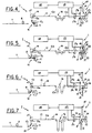
- the operating cyle of apparatus 1 also provides that during the initial moving step of the band 12 by rollers 27a, 27b in order to position and lock the front end 12b of the band itself, a first reading of one band surface should be executed in order to detect the passage of the first connecting seam 12a.
- This reading step is carried out by sensor means, preferably consisting of one or more photoelectric cells 46 secured to the machine 2 framework and acting on the point where the cut by the cutting member 18 is to be carried out, or at any other previously established point.
- the photoelectric cell 46 is connected to the electronic control box 29 to send a signal thereto at the moment that one of the connecting seams 12a passes on the cutting station 17.
- a seam marking step is preferably carried out on the band 12, upstream of said photoelectric cell.
- the marking is executed by a marking unit 47 known per se, preferably operating at the front edge 13a of the suspended surface 13.
- This marking unit puts a reflective white mark on each connecting seam 12a, for example by means of chalk, paint, labels or other means; the mark can also be of another colour which however must be capable of reflecting the light beam emitted by the photoelectric cell 46.
- one identification step for identifying the length of the leading portion 21 of the obtained piece or length is also carried out with the aid of the first encoder 28.
- the identification is executed by enabling the photoelectric cell 46 to reading, starting from the moment at which the moving of the band 12 through the rollers 27a, 27b begins, and disenabling the photoelectric cell 46 when the first encoder 28 has detected a displacement corresponding to the minimum distance value between the closing seam 24 and the nearest connecting seam 12a.
- the photoelectric cell 46 does not record the passage of any connecting seam 12a, it means that the leading portion 21 is longer than the minimum previously entered value and therefore the electronic control box 29 will command the execution of the controlled-dragging step by the guillotine element 38, after locking the front end 12b by means of the locking bar 30.
- the photoelectric cell 46 intercepts the passage of a connecting seam 12a during the first reading step, it means that the leading portion 21 of the obtained length is shorter than the minimum previously entered value.
- the electronic control box 29 will command the execution of an auxiliary cutting step by the cutting member 18, so as to cut off the band 12 upstream of the connecting seam 12a thereby producing a scrap of reduced length.
- a second reading step is carried out in order to detect the passage of the last seam 12a under the photoelectric cell 46.
- This reading step too is combined with a second identification step, carried out with the aid of the second encoder 40a, so as to detect the length of the trailing portion 22 of the length or piece 20 which is about to be formed.
- the above identification is carried out by enabling the photoelectric cell 46 to reading in register with a predetermined number of final pulses emitted by the second encoder 40a before the end of the controlled-dragging step.
- the electronic control box 29 enables the execution of the cut on the band 12 by the cutting member 18, as well as the following operations concerning the approaching of the opposite ends of the length and the connecting of the same.
- the electronic control box 29 commands the execution of an auxiliary controlled-dragging step so that, as a result, the width of the loop 44 will be modified and therefore also the length of the trailing portion 22 of the piece or length 20.
- the auxiliary controlled-dragging step is preceded by a search step during which the electronic control box 29 examines a memory 48 in which different sizes for the sleeves to be made are stored.
- the electronic control box 29 examines the various stored sizes searching for a wider size than that of the sleeve which was about to be made and, once it has found said size, causes a further descent of the guillotine element 38 in order to adapt the loop 44 to the formation of a sleeve having the new selected size.
- the trailing portion 22 of the length 20 will become therefore longer and its length will exceed the minimum previously entered value.
- the electronic control box 29 enables apparatus 1 to execute the cut of the length 20 and to connect the opposite ends of the latter together, in order to obtain the finished sleeve without producing any scrap.
Landscapes
- Engineering & Computer Science (AREA)
- Mechanical Engineering (AREA)
- Textile Engineering (AREA)
- Sewing Machines And Sewing (AREA)
Applications Claiming Priority (4)
| Application Number | Priority Date | Filing Date | Title |
|---|---|---|---|
| IT2189990 | 1990-10-29 | ||
| IT2189990A IT1244144B (it) | 1990-10-29 | 1990-10-29 | Procedimento ed apparecchiatura per realizzare manicotti tessili impiegati nella fabbricazione di cinghie di trasmissione. |
| IT2189890A IT1253003B (it) | 1990-10-29 | 1990-10-29 | Procedimento ed apparecchiatura per realizzare automaticamente manicotti tessili con cuciture trasversali distanziate oltre una misura minima prestabilita. |
| IT2189890 | 1990-10-29 |
Publications (1)
| Publication Number | Publication Date |
|---|---|
| EP0483728A1 true EP0483728A1 (de) | 1992-05-06 |
Family
ID=26328033
Family Applications (1)
| Application Number | Title | Priority Date | Filing Date |
|---|---|---|---|
| EP91118358A Withdrawn EP0483728A1 (de) | 1990-10-29 | 1991-10-28 | Verfahren und Vorrichtung zum Herstellen von Textilschläuchen |
Country Status (2)
| Country | Link |
|---|---|
| US (1) | US5255619A (de) |
| EP (1) | EP0483728A1 (de) |
Families Citing this family (6)
| Publication number | Priority date | Publication date | Assignee | Title |
|---|---|---|---|---|
| ES2189547B1 (es) * | 1998-12-17 | 2004-04-01 | Comercial De Tecnologia Sanitaria, S.A. | Maquina para el corte y soldadura de cinta continua de material plastico; en especial para cinturones de seguridad de vehiculos y similares. |
| PL2004456T3 (pl) * | 2006-03-07 | 2016-12-30 | Sposób i urządzenie do obróbki materiału wiotkiego w zginaniu | |
| US7975633B2 (en) | 2008-06-27 | 2011-07-12 | Miller Weldmaster Corporation | Bi-directional seaming machine |
| US9333662B2 (en) | 2012-10-04 | 2016-05-10 | Federal-Mogul Powertrain, Inc. | Method of cutting tubular members and apparatus therefor |
| US9862109B2 (en) | 2012-10-04 | 2018-01-09 | Federal-Mogul Powertrain Llc | Method of cutting tubular members and apparatus therefor |
| CN106276368A (zh) * | 2016-08-29 | 2017-01-04 | 伊士曼缝制机械(宁波)有限公司 | 一种硬质面料拉布机的气动夹具 |
Citations (7)
| Publication number | Priority date | Publication date | Assignee | Title |
|---|---|---|---|---|
| US3227118A (en) * | 1963-11-21 | 1966-01-04 | Riegel Textile Corp | Mechanism and method for automatically producing pillow cases, bags, and the like |
| EP0006009A1 (de) * | 1978-05-31 | 1979-12-12 | Leonard Thomas Frank Bryan | Verfahren und Vorrichtung zum Zertrennen eines fortlaufenden Bandes |
| US4323786A (en) * | 1980-07-03 | 1982-04-06 | Sparton Corporation | Seam detection and control system |
| US4465531A (en) * | 1981-11-25 | 1984-08-14 | Bridgestone Tire Company Limited | Method of forming a closed loop of a flexible strip |
| DE3639972A1 (de) * | 1986-11-22 | 1988-05-26 | Hauni Werke Koerber & Co Kg | Verfahren und einrichtung zum aussondern von durch fehlerstellen unbrauchbaren materialbahnabschnitten aus einer materialbahn |
| DE3730923A1 (de) * | 1987-09-15 | 1989-03-23 | Vni I K I Oboru Dlja Sinnoj Pr | Aggregat zum zuschneiden und zusammensetzen von streifenmaterial |
| US4968369A (en) * | 1988-10-03 | 1990-11-06 | Xerox Corporation | Belt fabrication machine |
Family Cites Families (11)
| Publication number | Priority date | Publication date | Assignee | Title |
|---|---|---|---|---|
| US4214541A (en) * | 1977-12-29 | 1980-07-29 | Fieldcrest Mills, Inc. | Method for manufacturing pillowcases |
| JPS59133034A (ja) * | 1983-01-20 | 1984-07-31 | Bando Chem Ind Ltd | 歯付ベルトの製造方法 |
| JPS6186355A (ja) * | 1984-10-03 | 1986-05-01 | Dainippon Screen Mfg Co Ltd | 長尺シ−ト材の継ぎ目及び終端の検出方法 |
| US4878985A (en) * | 1987-03-20 | 1989-11-07 | Xerox Corporation | Apparatus for preparing belts |
| US4932344A (en) * | 1987-05-19 | 1990-06-12 | Harold Tatum | Method for production of fitted sheets |
| US5020460A (en) * | 1987-05-20 | 1991-06-04 | Porter Sewing Machines, Inc. | Method and apparatus for aligning a fabric ply in a sewing machine |
| US5030313A (en) * | 1987-08-11 | 1991-07-09 | Mitsubishi Denki Kabushiki Kaisha | Apparatus for connecting strips |
| US4787525A (en) * | 1987-12-23 | 1988-11-29 | Michael Joyce | Child-resistant closures |
| US4858546A (en) * | 1988-03-02 | 1989-08-22 | Union Special Corporation | Hemmer seamer assembly |
| DE3818796C1 (de) * | 1988-06-03 | 1989-11-30 | Texpa-Arbter Maschinenbau Gmbh, 8741 Saal, De | |
| JPH0484989A (ja) * | 1990-07-26 | 1992-03-18 | Matsuya Hosei Kiki Hanbai Kk | 筒状物製造装置 |
-
1991
- 1991-10-28 EP EP91118358A patent/EP0483728A1/de not_active Withdrawn
- 1991-10-29 US US07/783,676 patent/US5255619A/en not_active Expired - Fee Related
Patent Citations (7)
| Publication number | Priority date | Publication date | Assignee | Title |
|---|---|---|---|---|
| US3227118A (en) * | 1963-11-21 | 1966-01-04 | Riegel Textile Corp | Mechanism and method for automatically producing pillow cases, bags, and the like |
| EP0006009A1 (de) * | 1978-05-31 | 1979-12-12 | Leonard Thomas Frank Bryan | Verfahren und Vorrichtung zum Zertrennen eines fortlaufenden Bandes |
| US4323786A (en) * | 1980-07-03 | 1982-04-06 | Sparton Corporation | Seam detection and control system |
| US4465531A (en) * | 1981-11-25 | 1984-08-14 | Bridgestone Tire Company Limited | Method of forming a closed loop of a flexible strip |
| DE3639972A1 (de) * | 1986-11-22 | 1988-05-26 | Hauni Werke Koerber & Co Kg | Verfahren und einrichtung zum aussondern von durch fehlerstellen unbrauchbaren materialbahnabschnitten aus einer materialbahn |
| DE3730923A1 (de) * | 1987-09-15 | 1989-03-23 | Vni I K I Oboru Dlja Sinnoj Pr | Aggregat zum zuschneiden und zusammensetzen von streifenmaterial |
| US4968369A (en) * | 1988-10-03 | 1990-11-06 | Xerox Corporation | Belt fabrication machine |
Also Published As
| Publication number | Publication date |
|---|---|
| US5255619A (en) | 1993-10-26 |
Similar Documents
| Publication | Publication Date | Title |
|---|---|---|
| CN101374641B (zh) | 从绗缝材料织物切割布块的方法和系统 | |
| US3871309A (en) | Shirt front assembly, method and apparatus | |
| ITTO960736A1 (it) | Dispositivo e procedimento per la cucitura di maniche su corpi camicia | |
| WO1999019552A9 (en) | Method and apparatus for sewing fabric panels | |
| US6802271B2 (en) | Automatic border sewing system | |
| US4932113A (en) | Manufacture of slide fasteners | |
| US4292908A (en) | Hemmer-seamer | |
| US5390614A (en) | Method and apparatus for automatically attaching a collarette display and label to a garment body by using a two step sewing operation | |
| EP0483728A1 (de) | Verfahren und Vorrichtung zum Herstellen von Textilschläuchen | |
| US3722435A (en) | Cloth cutting and hemming method and apparatus | |
| US4154180A (en) | Cutting and hemming system | |
| US3955515A (en) | Folding and hemming method and apparatus | |
| US4700642A (en) | Joining continuous lengths of web materials | |
| CA2171928C (en) | Sleeve making method and apparatus | |
| EP0052142A1 (de) | System zum herstellen blattförmiger stücke mit saumexpander. | |
| US4112860A (en) | Method of fabricating shirt cuffs | |
| CA2156893A1 (en) | Improved method and apparatus for sewing sleeves on shirt bodies | |
| US5040778A (en) | Apparatus for automatically inverting workpieces of limp sheet material | |
| US4048931A (en) | Style loop forming and attaching apparatus | |
| US4766661A (en) | Apparatus for applying a fabric material to a frame | |
| US5148760A (en) | Method and apparatus using clamps and movable plates for producing pleats | |
| US3963548A (en) | Apparatus and method of forming hemmed curtains and the like | |
| US4271774A (en) | Cutting and hemming system | |
| CN208762682U (zh) | 一种地垫包边设备 | |
| US4481006A (en) | Bag making method and machine |
Legal Events
| Date | Code | Title | Description |
|---|---|---|---|
| PUAI | Public reference made under article 153(3) epc to a published international application that has entered the european phase |
Free format text: ORIGINAL CODE: 0009012 |
|
| AK | Designated contracting states |
Kind code of ref document: A1 Designated state(s): DE ES FR |
|
| 17P | Request for examination filed |
Effective date: 19921023 |
|
| RAP1 | Party data changed (applicant data changed or rights of an application transferred) |
Owner name: DAYCO PTI S.P.A. |
|
| 17Q | First examination report despatched |
Effective date: 19960122 |
|
| STAA | Information on the status of an ep patent application or granted ep patent |
Free format text: STATUS: THE APPLICATION IS DEEMED TO BE WITHDRAWN |
|
| 18D | Application deemed to be withdrawn |
Effective date: 19960601 |