EP0483960A1 - Système de refroidissement pour four continu - Google Patents
Système de refroidissement pour four continu Download PDFInfo
- Publication number
- EP0483960A1 EP0483960A1 EP91308064A EP91308064A EP0483960A1 EP 0483960 A1 EP0483960 A1 EP 0483960A1 EP 91308064 A EP91308064 A EP 91308064A EP 91308064 A EP91308064 A EP 91308064A EP 0483960 A1 EP0483960 A1 EP 0483960A1
- Authority
- EP
- European Patent Office
- Prior art keywords
- kiln
- gas
- cooling
- cooling system
- inlet
- Prior art date
- Legal status (The legal status is an assumption and is not a legal conclusion. Google has not performed a legal analysis and makes no representation as to the accuracy of the status listed.)
- Withdrawn
Links
- 238000001816 cooling Methods 0.000 title claims abstract description 77
- 239000002826 coolant Substances 0.000 claims description 4
- XLYOFNOQVPJJNP-UHFFFAOYSA-N water Substances O XLYOFNOQVPJJNP-UHFFFAOYSA-N 0.000 claims description 3
- 238000000034 method Methods 0.000 claims description 2
- 238000007664 blowing Methods 0.000 abstract description 7
- 239000000498 cooling water Substances 0.000 abstract description 4
- 239000007789 gas Substances 0.000 description 31
- 239000000919 ceramic Substances 0.000 description 14
- 238000010304 firing Methods 0.000 description 7
- 238000010276 construction Methods 0.000 description 5
- 230000004048 modification Effects 0.000 description 4
- 238000012986 modification Methods 0.000 description 4
- 239000000126 substance Substances 0.000 description 4
- QVGXLLKOCUKJST-UHFFFAOYSA-N atomic oxygen Chemical compound [O] QVGXLLKOCUKJST-UHFFFAOYSA-N 0.000 description 3
- 230000000694 effects Effects 0.000 description 3
- 239000011261 inert gas Substances 0.000 description 3
- 239000001301 oxygen Substances 0.000 description 3
- 229910052760 oxygen Inorganic materials 0.000 description 3
- 229910001035 Soft ferrite Inorganic materials 0.000 description 2
- 230000002411 adverse Effects 0.000 description 2
- 239000000112 cooling gas Substances 0.000 description 2
- 238000010586 diagram Methods 0.000 description 2
- 230000005540 biological transmission Effects 0.000 description 1
Images
Classifications
-
- F—MECHANICAL ENGINEERING; LIGHTING; HEATING; WEAPONS; BLASTING
- F27—FURNACES; KILNS; OVENS; RETORTS
- F27B—FURNACES, KILNS, OVENS OR RETORTS IN GENERAL; OPEN SINTERING OR LIKE APPARATUS
- F27B9/00—Furnaces through which the charge is moved mechanically, e.g. of tunnel type; Similar furnaces in which the charge moves by gravity
- F27B9/12—Furnaces through which the charge is moved mechanically, e.g. of tunnel type; Similar furnaces in which the charge moves by gravity with special arrangements for preheating or cooling the charge
-
- F—MECHANICAL ENGINEERING; LIGHTING; HEATING; WEAPONS; BLASTING
- F27—FURNACES; KILNS; OVENS; RETORTS
- F27D—DETAILS OR ACCESSORIES OF FURNACES, KILNS, OVENS OR RETORTS, IN SO FAR AS THEY ARE OF KINDS OCCURRING IN MORE THAN ONE KIND OF FURNACE
- F27D9/00—Cooling of furnaces or of charges therein
-
- F—MECHANICAL ENGINEERING; LIGHTING; HEATING; WEAPONS; BLASTING
- F27—FURNACES; KILNS; OVENS; RETORTS
- F27B—FURNACES, KILNS, OVENS OR RETORTS IN GENERAL; OPEN SINTERING OR LIKE APPARATUS
- F27B9/00—Furnaces through which the charge is moved mechanically, e.g. of tunnel type; Similar furnaces in which the charge moves by gravity
- F27B9/12—Furnaces through which the charge is moved mechanically, e.g. of tunnel type; Similar furnaces in which the charge moves by gravity with special arrangements for preheating or cooling the charge
- F27B2009/124—Cooling
- F27B2009/126—Cooling involving the circulation of cooling gases, e.g. air
-
- F—MECHANICAL ENGINEERING; LIGHTING; HEATING; WEAPONS; BLASTING
- F27—FURNACES; KILNS; OVENS; RETORTS
- F27B—FURNACES, KILNS, OVENS OR RETORTS IN GENERAL; OPEN SINTERING OR LIKE APPARATUS
- F27B9/00—Furnaces through which the charge is moved mechanically, e.g. of tunnel type; Similar furnaces in which the charge moves by gravity
- F27B9/04—Furnaces through which the charge is moved mechanically, e.g. of tunnel type; Similar furnaces in which the charge moves by gravity adapted for treating the charge in vacuum or special atmosphere
- F27B9/045—Furnaces with controlled atmosphere
- F27B9/047—Furnaces with controlled atmosphere the atmosphere consisting of protective gases
-
- F—MECHANICAL ENGINEERING; LIGHTING; HEATING; WEAPONS; BLASTING
- F27—FURNACES; KILNS; OVENS; RETORTS
- F27B—FURNACES, KILNS, OVENS OR RETORTS IN GENERAL; OPEN SINTERING OR LIKE APPARATUS
- F27B9/00—Furnaces through which the charge is moved mechanically, e.g. of tunnel type; Similar furnaces in which the charge moves by gravity
- F27B9/14—Furnaces through which the charge is moved mechanically, e.g. of tunnel type; Similar furnaces in which the charge moves by gravity characterised by the path of the charge during treatment; characterised by the means by which the charge is moved during treatment
- F27B9/20—Furnaces through which the charge is moved mechanically, e.g. of tunnel type; Similar furnaces in which the charge moves by gravity characterised by the path of the charge during treatment; characterised by the means by which the charge is moved during treatment the charge moving in a substantially straight path
- F27B9/24—Furnaces through which the charge is moved mechanically, e.g. of tunnel type; Similar furnaces in which the charge moves by gravity characterised by the path of the charge during treatment; characterised by the means by which the charge is moved during treatment the charge moving in a substantially straight path being carried by a conveyor
- F27B9/2407—Furnaces through which the charge is moved mechanically, e.g. of tunnel type; Similar furnaces in which the charge moves by gravity characterised by the path of the charge during treatment; characterised by the means by which the charge is moved during treatment the charge moving in a substantially straight path being carried by a conveyor the conveyor being constituted by rollers (roller hearth furnace)
-
- F—MECHANICAL ENGINEERING; LIGHTING; HEATING; WEAPONS; BLASTING
- F27—FURNACES; KILNS; OVENS; RETORTS
- F27D—DETAILS OR ACCESSORIES OF FURNACES, KILNS, OVENS OR RETORTS, IN SO FAR AS THEY ARE OF KINDS OCCURRING IN MORE THAN ONE KIND OF FURNACE
- F27D7/00—Forming, maintaining or circulating atmospheres in heating chambers
- F27D7/04—Circulating atmospheres by mechanical means
- F27D2007/045—Fans
-
- F—MECHANICAL ENGINEERING; LIGHTING; HEATING; WEAPONS; BLASTING
- F27—FURNACES; KILNS; OVENS; RETORTS
- F27D—DETAILS OR ACCESSORIES OF FURNACES, KILNS, OVENS OR RETORTS, IN SO FAR AS THEY ARE OF KINDS OCCURRING IN MORE THAN ONE KIND OF FURNACE
- F27D9/00—Cooling of furnaces or of charges therein
- F27D2009/007—Cooling of charges therein
- F27D2009/0072—Cooling of charges therein the cooling medium being a gas
-
- Y—GENERAL TAGGING OF NEW TECHNOLOGICAL DEVELOPMENTS; GENERAL TAGGING OF CROSS-SECTIONAL TECHNOLOGIES SPANNING OVER SEVERAL SECTIONS OF THE IPC; TECHNICAL SUBJECTS COVERED BY FORMER USPC CROSS-REFERENCE ART COLLECTIONS [XRACs] AND DIGESTS
- Y02—TECHNOLOGIES OR APPLICATIONS FOR MITIGATION OR ADAPTATION AGAINST CLIMATE CHANGE
- Y02P—CLIMATE CHANGE MITIGATION TECHNOLOGIES IN THE PRODUCTION OR PROCESSING OF GOODS
- Y02P40/00—Technologies relating to the processing of minerals
- Y02P40/60—Production of ceramic materials or ceramic elements, e.g. substitution of clay or shale by alternative raw materials, e.g. ashes
Definitions
- This invention relates to a cooling system for a continuous kiln, particularly although not exclusively as used for firing ceramic products such as soft ferrite and other high-functioned ceramics, which need to be fired under low oxygen atmosphere in a cooling zone of the kiln.
- a conventional continuous kiln such as tunnel kiln and roller hearth kiln has preheating, firing, and cooling zones continuously in the longitudinal direction of the kiln. With such a construction, temperature and atmosphere of each zone is liable to be affected by neighbor zones.
- the problem addressed herein is to provide a new cooling system for a continuous kiln.
- the present invention provides a cooling system for a continuous kiln, comprising a gas circuit for introducing gas from inside a cooling zone from a exhaust port mounted on the cooling zone of the kiln via outside of a cooling zone into an inlet port mounted on the cooling zone of said kiln, an out-of-kiln heat exchanger provided on the gas circuit to absorb heat of said inner gas by a cooling medium and a blowing machine provided on said gas circuit, to circulate gas in said gas circuit. Also, a corresponding method.
- the exhaust port may be provided on the top closure or sidewalls of the cooling zone.
- the inlet port can be provided on sidewalls of the cooling zone, at the top closure of the kiln or at the kiln floor under carriages, yet preferably on the sidewalls in view of heat transmission.
- the cooling medium circulating in the out-of-kiln heat exchanger is, preferably, water or air. Water can cool the gas in the kiln more effectively than air as the cooling medium.
- the blowing machine is preferably an air blower or an air fan, yet it is not limited to these machines.
- the cooling system can allow to circulate large amount of cooling gas without introducing new fresh air that changes chemical composition, especially oxygen content in that cooling zone. Consequently, the length of the cooling zone can be shortened. Furthermore, the cooling system circulates inner gas of the cooling zone that enables proper control of temperature and atmosphere especially in cooling zone of the kiln, and ensures quick cooling of ceramic products. Further, since the cooling system can be made with a construction in which a certain amount of gas fulfilled in the kiln is circulated in the cooling zone, ceramic products are greatly prevented from having an adverse effect in preheating and firing zones.
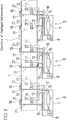
- a continuous kiln is a tunnel kiln comprising a kiln housing 1 and having preheating zone 1 a , firing zone 1 b , and cooling zone 1 c .
- Carriages 2 are conveyed in from an entrance of the tunnel kiln (in the left end of the kiln as viewed in FIGURE 2). As the carriages 2 move in the kiln along an arrow indicated in FIGURE 2, ceramic products 3 arranged on the carriages 2 are also carried along this arrow. The ceramic products arranged on the carriages 2 are heated at a temperature corresponding to a controlled temperature schedule in the kiln. After firing, the ceramic products 3 are carried out from an exit of the kiln (in the right end of the kiln as viewed in FIGURE 2).
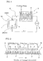
- a cooling system 5, as shown in FIGURE 1, is fitted with the cooling zone 1 c of the kiln housing 1 of the continuous kiln 10.
- a certain amount of gas fulfilled in the kiln is exhausted from exhaust ports 11 and 12 provided at a kiln chamber 4.
- the exhaust gas flows into a gas circuit 6, recycles in the gas circuit 6, and flows into inlet ports 20 and 21 provided at the cooling zone 1c of the kiln chamber 4.
- the gas circuit 6 is equipped with an out-of-kiln heat exchanger 7 and with a blowing machine 8 between the heat exchanger 7 and inlet ports 20 and 21.
- cooling water circulates to absorb heat of the gas taken out from the cooling zone.
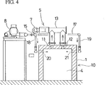
- Cooling system 5 Construction of the cooling system 5 is further shown more concretely in FIGURES 3 and 4.
- Exhaust ports 11 and 12 are provided at the top closure of the cooling zone 1 c of the continuous kiln 10. Such construction enables to cool the atmosphere of the cooling zone 1 c effectively.
- the exhaust ports 11 and 12 are connected with one end of a pipe 13 included in the above-mentioned gas circuit 6.
- the other end of the pipe 13 is connected with the out-of-kiln heat exchanger 7.
- the out-of-kiln heat exchanger 7 is arranged in such a manner that a cooling pipe in which cooling water circulates has a large surface to contact with circulating gas taken out from the kiln.
- the cooling water in the cooling pipe absorbs heat of and cools the circulating gas.
- a blowing machine 8 is provided on the downstream of the out-of-kiln heat exchanger 7 in such a manner that the cooled gas is sent to a pipeline 15 by the blowing machine 8.
- the pipeline 15 is divaricated into branch pipes 16 and 17.
- Each of the branch pipes 16 and 17 is connected respectively with one end of pipelines 18 and 19 arranged on sidewalls of the cooling zone 1 c of the continuous kiln 10.
- Each of the other ends of the pipelines 18 and 19 communicates respectively with inlet ports 20 and 21 provided on the sidewalls of the continuous kiln 10.
- One inlet port 20 is provided at one sidewall and the other inlet port 21 is provided on the opposite sidewall of the cooling zone 1 c of the continuous kiln 10, so that the exhaust gas injected from each of the inlet ports 20 and 21 into the kiln chamber and collide with one another. Additionally, each of the inlet ports 20 and 21 is offset, as shown in FIGURE 3, at a position of the exhaust ports 11 and 12 respectively in the longitudinal direction of the cooling zone so that the gas circulating in the cooling zone has a good cooling effect.
- the exhausted gas flows through the exhaust ports 11 and 12 via the pipe 13 into the out-of-kiln heat exchanger 7, in which the exhaust gas releases heat and cools down.
- the cooled gas is blown by the blowing machine 8 through the pipeline 15, the branch pipes 16 and 17, the pipelines 18 and 19, and exhaust ports 20 and 21, into the kiln chamber.
- the atmosphere gas at the cooling zone 1 c is cooled without chemical composition being changed in the continuous kiln 10.
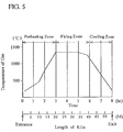
- Temperature of the gas in the kiln chamber rises gradually in preheating zone, taking highest point in firing zone, and declining in cooling zone. Ceramic products fired in the firing zone are cooled rapidly by the above-explained cooling system 5 in the cooling zone 1 c shown in FIGURE 2.
- the cooling system 5 provided in the cooling zone 1 c eliminates introducing fresh cooling air out of the kiln that can avoid having adverse effect in the cooling zone 1 c .
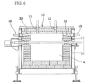
- FIGURE 6 A modification of the invention which is applied to roller hearth kiln is shown in FIGURE 6 illustrating the cross section of a cooling system viewed from an entrance of a kiln.
- Inlet ports 30 and 31 are provided on sidewalls of the kiln in such a manner that each of the ports 30 and 31 faces one another and nozzles of the inlet ports 30 and 31 slant, upwardly and inwardly, as seen in FIGURE 6. With such construction, ceramic products to be fired carried on setters are protected from direct cool blow. Since the other parts of the modification correspond to those of the above-described embodiment shown in FIGURE 4, same numerals are given to the substantially equal parts and detailed explanation of the modification is omitted.
- the gas in the interior space of the kiln, and which is circulated is an inert gas containing not more than small quantities of 02.
- N2 containing 10 ⁇ 4-1% O2 was used.
- the gas will also include a small amount of other gases generated at the surfaces of the ceramic products during operation.
Landscapes
- Engineering & Computer Science (AREA)
- Mechanical Engineering (AREA)
- General Engineering & Computer Science (AREA)
- Furnace Details (AREA)
- Tunnel Furnaces (AREA)
- Waste-Gas Treatment And Other Accessory Devices For Furnaces (AREA)
Applications Claiming Priority (2)
| Application Number | Priority Date | Filing Date | Title |
|---|---|---|---|
| JP2245081A JPH04124586A (ja) | 1990-09-14 | 1990-09-14 | 連続炉の冷却装置 |
| JP245081/90 | 1990-09-14 |
Publications (1)
| Publication Number | Publication Date |
|---|---|
| EP0483960A1 true EP0483960A1 (fr) | 1992-05-06 |
Family
ID=17128320
Family Applications (1)
| Application Number | Title | Priority Date | Filing Date |
|---|---|---|---|
| EP91308064A Withdrawn EP0483960A1 (fr) | 1990-09-14 | 1991-09-03 | Système de refroidissement pour four continu |
Country Status (3)
| Country | Link |
|---|---|
| EP (1) | EP0483960A1 (fr) |
| JP (1) | JPH04124586A (fr) |
| MX (1) | MX9101055A (fr) |
Cited By (2)
| Publication number | Priority date | Publication date | Assignee | Title |
|---|---|---|---|---|
| CN109114863A (zh) * | 2018-08-21 | 2019-01-01 | 深圳市鹰慧科技有限公司 | 一种循环冷却炉体 |
| US11796252B2 (en) | 2018-08-22 | 2023-10-24 | Ngk Insulators, Ltd. | Continuous heating furnace and operating method thereof |
Families Citing this family (5)
| Publication number | Priority date | Publication date | Assignee | Title |
|---|---|---|---|---|
| WO2007102217A1 (fr) * | 2006-03-08 | 2007-09-13 | Ibiden Co., Ltd. | refroidisseur de corps cuit, four de cuisson, procédé de refroidissement de corps cuit céramique, et processus de fabrication de structure alvéolaire |
| JP2008175517A (ja) * | 2006-03-08 | 2008-07-31 | Ibiden Co Ltd | 焼成体用冷却機、焼成炉、セラミック焼成体の冷却方法、及び、ハニカム構造体の製造方法 |
| JP4898649B2 (ja) * | 2007-12-20 | 2012-03-21 | 光洋サーモシステム株式会社 | 徐冷炉 |
| CN109028971B (zh) * | 2018-09-07 | 2024-05-07 | 乾县西北琉璃有限责任公司 | 青砖窑充分水冷循环系统 |
| JP7661283B2 (ja) | 2022-06-29 | 2025-04-14 | 日本碍子株式会社 | 加熱炉 |
Citations (5)
| Publication number | Priority date | Publication date | Assignee | Title |
|---|---|---|---|---|
| DE607099C (de) * | 1933-07-15 | 1934-12-17 | Siemens Schuckertwerke Akt Ges | Elektrisch beheizter Tunnel- oder Kanalofen |
| FR1261890A (fr) * | 1959-08-05 | 1961-05-26 | Aton Planungs & Baugesellschaft Fuer Die Keramische Industrie Mbh | Procédé d'exploitation de fours tunnels et chariot de cuisson destiné à l'application de ce procédé |
| DE3015844A1 (de) * | 1980-04-24 | 1981-10-29 | Paul Schneider Rohrleitungsbau GmbH, 8633 Rödental | Endkuehlzone eines tunnelofens |
| FR2599483A1 (fr) * | 1986-05-27 | 1987-12-04 | Chugai Ro Kogyo Kaisha Ltd | Four a zone de refroidissement lent |
| EP0257218A2 (fr) * | 1986-08-09 | 1988-03-02 | Hans Lingl Anlagenbau und Verfahrenstechnik GmbH & Co. KG | Four tunnel pour la cuisson réductrice de briques de mur extérieur |
Family Cites Families (1)
| Publication number | Priority date | Publication date | Assignee | Title |
|---|---|---|---|---|
| JPS6358201A (ja) * | 1986-08-27 | 1988-03-14 | ジヨ−ン・パ−ク | T定規装置 |
-
1990
- 1990-09-14 JP JP2245081A patent/JPH04124586A/ja active Pending
-
1991
- 1991-09-03 EP EP91308064A patent/EP0483960A1/fr not_active Withdrawn
- 1991-09-12 MX MX9101055A patent/MX9101055A/es not_active IP Right Cessation
Patent Citations (5)
| Publication number | Priority date | Publication date | Assignee | Title |
|---|---|---|---|---|
| DE607099C (de) * | 1933-07-15 | 1934-12-17 | Siemens Schuckertwerke Akt Ges | Elektrisch beheizter Tunnel- oder Kanalofen |
| FR1261890A (fr) * | 1959-08-05 | 1961-05-26 | Aton Planungs & Baugesellschaft Fuer Die Keramische Industrie Mbh | Procédé d'exploitation de fours tunnels et chariot de cuisson destiné à l'application de ce procédé |
| DE3015844A1 (de) * | 1980-04-24 | 1981-10-29 | Paul Schneider Rohrleitungsbau GmbH, 8633 Rödental | Endkuehlzone eines tunnelofens |
| FR2599483A1 (fr) * | 1986-05-27 | 1987-12-04 | Chugai Ro Kogyo Kaisha Ltd | Four a zone de refroidissement lent |
| EP0257218A2 (fr) * | 1986-08-09 | 1988-03-02 | Hans Lingl Anlagenbau und Verfahrenstechnik GmbH & Co. KG | Four tunnel pour la cuisson réductrice de briques de mur extérieur |
Cited By (2)
| Publication number | Priority date | Publication date | Assignee | Title |
|---|---|---|---|---|
| CN109114863A (zh) * | 2018-08-21 | 2019-01-01 | 深圳市鹰慧科技有限公司 | 一种循环冷却炉体 |
| US11796252B2 (en) | 2018-08-22 | 2023-10-24 | Ngk Insulators, Ltd. | Continuous heating furnace and operating method thereof |
Also Published As
| Publication number | Publication date |
|---|---|
| JPH04124586A (ja) | 1992-04-24 |
| MX9101055A (es) | 1992-05-04 |
Similar Documents
| Publication | Publication Date | Title |
|---|---|---|
| US4627814A (en) | Continuous type atmosphere heat treating furnace | |
| US4588378A (en) | Continuous heat treating furnace for metallic strip | |
| EP0483960A1 (fr) | Système de refroidissement pour four continu | |
| US4225121A (en) | Energy efficient heat-treating furnace system | |
| US4148600A (en) | Heat treatment furnace for metal strip | |
| EP0127697B1 (fr) | Appareillage pour purifier et faire circuler l'air chaud pour le traitement à la chaleur des étoffes textiles | |
| HU214053B (en) | Apparatus for drying and/or firing of ceramic articles | |
| US4449923A (en) | Continuous heat-treating furnace | |
| US4568274A (en) | Heat treating furnace for metallic strip | |
| US4628615A (en) | Process and installation for the heat treatment of cylindrical bodies, especially pipes | |
| JP2928843B2 (ja) | 雰囲気炉及び雰囲気炉の雰囲気維持方法 | |
| JPH03257119A (ja) | ローラハース式真空炉 | |
| US4310301A (en) | Combination burner and exhaust gas recirculation system for a carbottom furnace | |
| US3279774A (en) | Annealing furnace | |
| JPS6038637B2 (ja) | 高温焼成物の製造プロセスにおけるグレ−ト式エア−クエンチングク−ラの排熱回収方法及び排熱回収装置 | |
| JPS6320885B2 (fr) | ||
| GB2045408A (en) | Furnace system | |
| JPH0418008B2 (fr) | ||
| SU771433A1 (ru) | Печь непрерывного действи дл нагрева металла | |
| US1911089A (en) | Kiln | |
| JPH055883B2 (fr) | ||
| SU934169A1 (ru) | Туннельна печь дл термообработки марганец-цинковых ферритов | |
| JPH01139986A (ja) | ウォーキングビーム加熱炉 | |
| JPS592104Y2 (ja) | 熱処理炉 | |
| US3445098A (en) | Method and device for improving the temperature equalization of gases in tunnel furnaces and ovens |
Legal Events
| Date | Code | Title | Description |
|---|---|---|---|
| PUAI | Public reference made under article 153(3) epc to a published international application that has entered the european phase |
Free format text: ORIGINAL CODE: 0009012 |
|
| AK | Designated contracting states |
Kind code of ref document: A1 Designated state(s): BE DE ES FR GB IT SE |
|
| STAA | Information on the status of an ep patent application or granted ep patent |
Free format text: STATUS: THE APPLICATION IS DEEMED TO BE WITHDRAWN |
|
| 18D | Application deemed to be withdrawn |
Effective date: 19921107 |