EP0483973B1 - Ultrasonisches Schneidverfahren - Google Patents
Ultrasonisches Schneidverfahren Download PDFInfo
- Publication number
- EP0483973B1 EP0483973B1 EP91308908A EP91308908A EP0483973B1 EP 0483973 B1 EP0483973 B1 EP 0483973B1 EP 91308908 A EP91308908 A EP 91308908A EP 91308908 A EP91308908 A EP 91308908A EP 0483973 B1 EP0483973 B1 EP 0483973B1
- Authority
- EP
- European Patent Office
- Prior art keywords
- stock material
- blade
- anvil
- cutting
- ultrasonic
- Prior art date
- Legal status (The legal status is an assumption and is not a legal conclusion. Google has not performed a legal analysis and makes no representation as to the accuracy of the status listed.)
- Expired - Lifetime
Links
Images


Classifications
-
- B—PERFORMING OPERATIONS; TRANSPORTING
- B26—HAND CUTTING TOOLS; CUTTING; SEVERING
- B26D—CUTTING; DETAILS COMMON TO MACHINES FOR PERFORATING, PUNCHING, CUTTING-OUT, STAMPING-OUT OR SEVERING
- B26D7/00—Details of apparatus for cutting, cutting-out, stamping-out, punching, perforating, or severing by means other than cutting
- B26D7/08—Means for treating work or cutting member to facilitate cutting
- B26D7/086—Means for treating work or cutting member to facilitate cutting by vibrating, e.g. ultrasonically
-
- B—PERFORMING OPERATIONS; TRANSPORTING
- B29—WORKING OF PLASTICS; WORKING OF SUBSTANCES IN A PLASTIC STATE IN GENERAL
- B29D—PRODUCING PARTICULAR ARTICLES FROM PLASTICS OR FROM SUBSTANCES IN A PLASTIC STATE
- B29D30/00—Producing pneumatic or solid tyres or parts thereof
- B29D30/06—Pneumatic tyres or parts thereof (e.g. produced by casting, moulding, compression moulding, injection moulding, centrifugal casting)
- B29D30/38—Textile inserts, e.g. cord or canvas layers, for tyres; Treatment of inserts prior to building the tyre
- B29D30/46—Cutting textile inserts to required shape
-
- Y—GENERAL TAGGING OF NEW TECHNOLOGICAL DEVELOPMENTS; GENERAL TAGGING OF CROSS-SECTIONAL TECHNOLOGIES SPANNING OVER SEVERAL SECTIONS OF THE IPC; TECHNICAL SUBJECTS COVERED BY FORMER USPC CROSS-REFERENCE ART COLLECTIONS [XRACs] AND DIGESTS
- Y10—TECHNICAL SUBJECTS COVERED BY FORMER USPC
- Y10T—TECHNICAL SUBJECTS COVERED BY FORMER US CLASSIFICATION
- Y10T83/00—Cutting
- Y10T83/202—With product handling means
- Y10T83/2092—Means to move, guide, or permit free fall or flight of product
- Y10T83/2096—Means to move product out of contact with tool
- Y10T83/2135—Moving stripper timed with tool stroke
- Y10T83/215—Carried by moving tool element or its support
-
- Y—GENERAL TAGGING OF NEW TECHNOLOGICAL DEVELOPMENTS; GENERAL TAGGING OF CROSS-SECTIONAL TECHNOLOGIES SPANNING OVER SEVERAL SECTIONS OF THE IPC; TECHNICAL SUBJECTS COVERED BY FORMER USPC CROSS-REFERENCE ART COLLECTIONS [XRACs] AND DIGESTS
- Y10—TECHNICAL SUBJECTS COVERED BY FORMER USPC
- Y10T—TECHNICAL SUBJECTS COVERED BY FORMER US CLASSIFICATION
- Y10T83/00—Cutting
- Y10T83/444—Tool engages work during dwell of intermittent workfeed
- Y10T83/4645—With means to clamp work during dwell
-
- Y—GENERAL TAGGING OF NEW TECHNOLOGICAL DEVELOPMENTS; GENERAL TAGGING OF CROSS-SECTIONAL TECHNOLOGIES SPANNING OVER SEVERAL SECTIONS OF THE IPC; TECHNICAL SUBJECTS COVERED BY FORMER USPC CROSS-REFERENCE ART COLLECTIONS [XRACs] AND DIGESTS
- Y10—TECHNICAL SUBJECTS COVERED BY FORMER USPC
- Y10T—TECHNICAL SUBJECTS COVERED BY FORMER US CLASSIFICATION
- Y10T83/00—Cutting
- Y10T83/748—With work immobilizer
-
- Y—GENERAL TAGGING OF NEW TECHNOLOGICAL DEVELOPMENTS; GENERAL TAGGING OF CROSS-SECTIONAL TECHNOLOGIES SPANNING OVER SEVERAL SECTIONS OF THE IPC; TECHNICAL SUBJECTS COVERED BY FORMER USPC CROSS-REFERENCE ART COLLECTIONS [XRACs] AND DIGESTS
- Y10—TECHNICAL SUBJECTS COVERED BY FORMER USPC
- Y10T—TECHNICAL SUBJECTS COVERED BY FORMER US CLASSIFICATION
- Y10T83/00—Cutting
- Y10T83/869—Means to drive or to guide tool
- Y10T83/8821—With simple rectilinear reciprocating motion only
- Y10T83/8822—Edge-to-edge of sheet or web [e.g., traveling cutter]
-
- Y—GENERAL TAGGING OF NEW TECHNOLOGICAL DEVELOPMENTS; GENERAL TAGGING OF CROSS-SECTIONAL TECHNOLOGIES SPANNING OVER SEVERAL SECTIONS OF THE IPC; TECHNICAL SUBJECTS COVERED BY FORMER USPC CROSS-REFERENCE ART COLLECTIONS [XRACs] AND DIGESTS
- Y10—TECHNICAL SUBJECTS COVERED BY FORMER USPC
- Y10T—TECHNICAL SUBJECTS COVERED BY FORMER US CLASSIFICATION
- Y10T83/00—Cutting
- Y10T83/97—Miscellaneous
Definitions
- This invention relates to an ultrasonic cutting apparatus for stock material, and in particular to an ultrasonic cutting apparatus for employing a blade adapted to ultrasonically cut tyre stock material at a low angle.
- the invention also relates to a method of ultrasonically cutting stock material.
- a tyre typically includes plies of various types, including, for example, an inner ply. These plies may be formed from a long sheet of rubber stock material by cutting the stock material to appropriate lengths and folding the end portions together to form a generally annular shape adapted to become part of a tyre carcass. The two end portions of the stock material are typically overlapped a small amount and may be bonded together, for example, by adhesively bonding, or "stitching" the end portions together under pressure. The overlap of the ply ends results in a limited circumferential portion of these plies having a slight radial build-up, which cannot be avoided with known cutting techniques.
- the stock material is supported on a processing table and the blade is forced into the material.
- the blade is moved across the width of the stock material to cut off the desired length of material.
- the stock material is typically formed from rubber based products which are flexible and "sticky" to the touch.
- the material tends to move or vibrate as the blade traverses the material, thereby increasing the cutting time and decreasing the quality of the cut.
- the blade must cut the stock material at an angle substantially perpendicular to the processing table, or the stock material will tend to bunch up in front of the blade.
- the perpendicular angle of cut results in a cut edge having a reduced surface area, thereby making it difficult to splice the cut surfaces to one another in the tyre building process. Consequently, it is necessary to overlap the ply end portions a small amount and adhesively bond or "stitch" them together under pressure.
- U.S. Patent No. 4,711,693 shows an anvil comprising an elongated, substantially rectangular housing in which a piston is disposed for motion relative to the housing.
- the anvil includes a slitting implement advanced by the piston.
- the textile material is fed through the nip between the slitting implement and ultrasonic horn.
- the ultrasonic horn is undergoing vibratory motion to cut the textile material held thereagainst.
- EP-A-0324199 discloses a method and apparatus for ultrasonically cutting stock material.
- the apparatus includes means for temporarily adhesively securing the stock material to an anvil; a carriage assembly moveable transversely across the width of the anvil; and ultrasonic cutting tool mounted on said carriage and having a cutting blade coupled thereto, the blade being capable of resonating in response to ultrasonic energy travelling longitudinally therethrough.
- the arrangement is such that when the carriage assembly moves transversely across the anvil, the blade cuts through and across the top of the stock material.
- the blade can be positioned with an angle between 10 and 90 degrees with respect to the stock material.
- EP-A-0240972, EP-A-0284761 and US-A-4516451 disclose tyres that have been cut at lob angles using known cutting methods. Additionally, it is known that attempts have been made to cut tyre sidewall material with a conventional blade at angles as small as 23° with respect to the horizontal, and then splice the cut ends together with a bevel lap splice. However, it has been found that a bevel lap splice of 23° or more in a sidewall does not adhere well without additional glues or adhesives and can become separated under normal tire operating conditions.
- an ultrasonic cutting apparatus for stock material having an anvil, means for temporarily securing the stock material to the anvil, a carriage assembly moveable across the width of the anvil, an ultrasonic cutting tool mounted on said carriage, said cutting tool having a blade mechanically coupled thereto, said blade resonating in response to ultrasonic energy travelling longitudinally therethrough; the ultrasonic cutting tool being mounted in respect of the anvil such that the blade extends at an angle of about 5 to 10 degrees with respect to the horizontal for stock material under 0.49 cm. thickness or, for stock material of thickness greater than 0.49 cm., at an angle such that the cut surface of the stock material has a width between about 1.00 cm.
- the apparatus includes a device slidable relative to the anvil and capable of engaging the stock material positioned at a location behind said blade to separate the stock material from the anvil after the blade has cut the stock material.
- an ultrasonic cutting system having a blade adapted to ultrasonically cut stock material at a low angle.
- a preferred embodiment of an ultrasonic cutting system according to the invention comprises a processing table, a carriage assembly adapted to move transversely across the width of the processing table, and an ultrasonic cutting tool mounted on the carriage assembly.
- the processing table has an anvil incorporated therein.
- the anvil comprises two parallel strips of plastic or Lexan (Registered Trade Mark) material mounted on a beam or a base.
- the parallel strips extend across the width of the anvil and define a guide channel therebetween for slidably receiving and guiding part of the carriage assembly.
- the carriage assembly of the preferred embodiment of the ultrasonic cutting apparatus is adapted to move transversely across the anvil on two stationery parallel rods positioned above the anvil.
- the rods respectively are received in and pass through bearing blocks, which are part of the main carriage body of the carriage assembly.
- the carriage assembly of the preferred embodiment also includes a set of rollers which are mounted on the distal ends of arms extending downwardly from the carriage body.
- the set of rollers include a first and second roller, wherein the second roller is located between the blade and the first roller.
- the rollers are adapted to travel ahead of the blade as the carriage traverses the stock material, with the first roller leading the second roller.
- the two rollers apply a predetermined amount of downwardly directed pressure on the stock material to removably bond or "stitch" the stock material to the anvil positioned therebelow.
- the ultrasonic cutting apparatus is mounted on the carriage such that the blade extends at a low angle, preferably at an angle of about 5° to 10° with respect to the horizontal.
- the blade is also offset forwardly from the carriage assembly at an angle of approximately 15° relative to a normal or transverse plane across the carriage assembly.
- the low angle of the blade creates a beveled cut having a width of between about 1.00 cm and 2.88 cm.
- the carriage assembly may further include a substantially L-shaped shoe extending downwardly therefrom.
- the shoe travels behind the blade when the carriage is moving across the anvil, and is adapted to lift and remove the cut portion of +he stock material from the anvil.
- the bottom portion of the shoe includes a downwardly extending guide projection slidingly received in the anvil guide channel to maintain the alignment of the carriage assembly with the anvil and processing table.
- the carriage assembly includes an ultrasonic cutting apparatus having a transducer and a cutting blade.
- the transducer and blade are mounted toward the side of the carriage body and extend at an angle downwardly therefrom.
- the cutting apparatus is part of, and moves concurrently with, the carriage assembly as it traverses the stock material.
- the transducer produces ultrasonic energy which is applied to the blade to create compression waves axially therealong.
- a method of ultrasonically cutting stock material comprising the steps of:
- step of cutting the stock material said step of cutting the stock material with a blade comprises cutting the stock material at an offset angle of about 0 to 15 degrees relative to an axis normal to the anvil.
- the method includes the further step of dampening vertical oscillations of said blade.
- a low angle cut of the stock material By providing an ultrasonic cutting system that uses ultrasonic energy to cut stock material, a low angle cut of the stock material can be achieved.
- the low angle cut results in a cut edge having an increased and "tacky" surface area, which facilitates splicing the cut surface of the stock material together with a bevel lap splice without using additional glues or adhesives.
- the bevel lap splice provides for a substantially seamless bond of the stock material and eliminates radial build-up along the seam.
- the bevel lap splice improves the balance of the tyre and reduces both the radial forces on the splice and the tyre cure time. Additionally, the material savings in eliminating the end ply overlap reduces the overall cost of the tyre.
- an ultrasonic cutting system 1 having an ultrasonically energized blade adapted to cut stock material at a low angle.
- an ultrasonic cutting system 1 according to the prevent invention comprises a processing table, indicated generally at 2, a carriage assembly adapted to move transversely across the width of the processing table, indicated generally at 3, and an ultrasonic cutting tool mounted on the carriage assembly, indicated generally at 4.
- the processing table 2 of the cutting system is normally located in a stock material processing line.
- the processing table 2 supports the stock material as it is fed from the stock material supply through the cutting station. At the cutting station, the stock material is cut into lengths, which are then formed into a tire ply for incorporation into a green tire as it is being built.
- the processing table 2 includes a feed table 6 and an anvil, indicating generally at 7, mounted in end to end relationship to one another.
- the anvil 7 includes, a base 8, a front strip 9 and a back strip 10 of plastic or Lexan (Registered Trade Mark) material.
- These parallel strips 9, 10 extend across the width of the base 8 and are secured to the top of the base 8 by screws or other conventional means.
- the parallel strips extend across the anvil 7 in close proximity to one another to form a guide channel therebetween, as shown at 12.
- the top surfaces of strips 9 and 10 preferably lie in a common plane with the top surface of feed table 6.
- the feed table 6 may include a conveyor for automatically advancing stock material 13 to the anvil at the cutting station.
- the stock material 13 is advanced in the longitudinal direction of arrow 14, with the term “upstream” meaning to the left of the cutting station, and the term “downstream” meaning to the right of the cutting station, as viewed in Fig. 1.
- the stock material 13 downstream of the cutting station may be supported by a rotatable shaft 15 as shown in Fig. 7, or by a downstream, run-out table (not shown).
- the shaft 15 or run-out table form part of the overall processing table.
- the carriage assembly 3 of the ultrasonic cutting system is adapted to move transversely across the anvil 7 on two parallel and transversely extending rods 17 and 18 positioned above the table.
- the rods respectively pass through bearing blocks 19 and 20 on the carriage assembly.
- the bearing blocks contain bearings therein to permit the carriage assembly 3 to selectively move along the rods 17, 18 transversely across the width of the stock material 13.
- the lateral movement of the carriage assembly along the rods is controlled by a conventional motor, such as a servo motor (not shown), which can be either mounted on or near the table or on the carriage assembly.
- the carriage assembly 3 further includes a carriage body 22, as best shown in Fig. 5.
- the carriage body 22 extends transversely between and is fixedly secured to the bottom of bearing blocks 19 and 20.
- a vertically extending hanger 23 is connected to and extends downwardly from the upstream end of the carriage body 22.
- a support plate 24 is secured to and extends horizontally outwardly from the bottom of hanger 23.
- the support plate 24 can be selectively transversely adjusted relative to hanger 23.
- the hanger has elongated slots 26 therein respectively receiving bolts 27 on the support plate to allow selective transverse adjustment of the support plate 24 relative to the hanger 23.
- Nuts 25 on bolts 27 may be selectively drawn down against vertically extending hanger 23 to secure the support plate 24 in the selected transverse position relative to the vertically extending hanger 23.
- the support plate 24 has a roller support flange 29 secured to the upstream end thereof.
- the vertically extending flange 29 may be transversely adjusted relative to the support plate 24.
- spaced bolts 31 on the upstream end of the support plate 24 are received in a horizontal, elongated slot 32 in the upper end of flange 29.
- Nuts 30 on bolts 31 may be selectively drawn down against backup member 33 to secure the roller support flange 29 in the selected transverse position relative to support plate 24.
- the support flange 29 has a first roller shaft 35 mounted thereon adjacent the bottom thereof.
- Roller shaft 35 extends through a mounting hole in support flange 29 and is secured thereto to mount roller shaft 35 above and in a parallel relationship to strip 10 of anvil 7.
- a first, relatively wide roller 36 is rotatably mounted on shaft 35.
- the roller 36 preferably has a number of outwardly extending ribs extending circumferentially therearound. The first roller 36 applies pressure to the stock material 13 positioned between the first roller 36 and the anvil 7, as will be described in more detail hereinafter.
- the support plate 24 has a plurality of tapped holes 37 extending therethrough to selectively receive a threaded shaft 38 in the selected position relative to the anvil.
- the height of the shaft may be adjusted upwardly or downwardly relative to support plate 24 by turning the shaft in one direction or the other.
- the bottom of shaft 38 has a yoke 39 mounted thereon which extends downwardly therefrom.
- the yoke 39 includes two parallel and downwardly extending arms 40, 41.
- a second roller shaft 42 extends between and is mounted to downwardly extending arms 40, 41.
- the roller shaft 42 is above and in parallel relationship to the strip 10 of anvil 7.
- a second, relatively narrow roller 43 is rotatably mounted on second roller shaft 42.
- the second roller 43 applies concentrated, downwardly directed pressure to the stock material 13 positioned between the second roller 43 and the anvil strip 10, as will be described in more detail hereinafter.
- the rollers 36, 43 may additionally include a spring bias to increase the downward pressure on the stock material.
- a spring 44 can be inserted between the yoke 39 and support plate 24 to bias roller 43 downwardly toward the anvil.
- the spring 44 is adapted to maintain a predetermined downward pressure on the anvil 7, yet be flexible enough to allow the yoke to be raised to insert the stock material between the second roller 43 and the anvil.
- the rollers 36 and 43 are spaced a predetermined distance apart from each other, with each roller having an edge aligned with the inside edge of the back strip 10 of anvil 7, on the side closest to the carriage guide channel 12.
- each roller 36, 43 is adapted to roll across strip 10 with the inside edges of the rollers being in alignment with the inside edge of the strip 10.
- the rollers are located at a position on the carriage assembly such that the first roller 36 is adapted to provide the initial, general stitching of the stock material 13, while the second roller 43 is adapted to provide a localized stitch of the stock material 13, just slightly ahead of a blade 46 on the ultrasonic cutting tool 4.
- the first and second rollers provide sufficient downward pressure on the stock material 13 to temporarily bond or "stitch" the material to the anvil 7.
- the stock material 13 is typically formed from petroleum-based products which are “sticky” or “tacky” to the touch, and hence can be temporarily adhesively bonded to a surface. Adhesively bonding the stock material just ahead of the blade permits the blade 46 to traverse the stock material at a low angle without the material moving or vibrating. Moreover, after the blade 46 has traversed the stock material 13, the material may be easily removed from the processing table by merely “peeling" it away.
- the blade 46 has sharpened edges and is mechanically coupled to a transducer, indicated generally at 47, within a housing 48.
- the transducer 47, blade 46 and housing 48 together cooperatively form an ultrasonic cutting tool 4 which is mounted toward the side of the carriage assembly 3.
- the cutting tool moves concurrently with the carriage assembly 3 as it traverses the stock material.
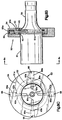
- the transducer 47 consists of a crystal stack, indicated generally at 50, and a horn 51 which are coupled together by a stud bolt (not shown).
- the stack 50 and horn 51 are mounted within the transducer housing 48 by a suspension assembly, indicated generally at 53, which insulates the housing from the ultrasonic energy.
- the suspension assembly 53 for example, includes an outer ring 54, an inner ring 52 and two O-rings 45, disposed between the inner ring and opposite sides of flange 51a on the horn.
- the outer ring has four tapped bores 65A (Fig. 8C) therein spaced 90° apart from one another.
- the four tapped bores 65A are respectively in radial alignment with four circumferentially spaced bores 65B in inner ring 52 and four circumferentially spaced bores 65C in the horn 51.
- pins As shown in Fig. 8C, four pins, indicated generally at 66, disposed 90° apart from each other, extend radially inward in aligned bores 65A-C from the outer ring 54 into the horn 51.
- the pins 66 have threaded heads 66A at their radially outer ends to allow the pins to be held in position by the threaded connection between the heads 66A and the tapped bores 65A. This threaded connection on the pins secures the suspension assembly 53 to the horn 51 and prevents the horn 51 from rotating within the suspension assembly 53.
- the outer ends of the heads 66A of pins 66 are received within the confines of bores 65A to help prevent ultrasonic energy loss through the pins to the suspension assembly 53. Further, the suspension assembly 53 is located at a position along the transducer 47 that corresponds to an ultrasonic energy nodal point, such that a minimum amount of energy is lost by transmission through the suspension assembly 53.
- the horn 51 of the transducer 47 extends forwardly from its coupling with the stack and narrows down to a forward necked end, shown generally at 55 in Fig. 8A, a portion of which protrudes from the transducer housing.
- a holder 55a is mechanically coupled to the necked end 55 by a stud bolt (not shown).
- the holder 55a has a blind end bore (not shown) in the forward end which is adapted to receive the rear end of blade 46.
- the blade 46 is mechanically soldered within the blind end bore by conventional processes.
- the crystal stack 50 is ultrasonically driven by a set of piezo-electric crystals, shown generally at 56, which are located at the end of the crystal stack 50 and which are mechanically coupled thereto by compression bolt 56a.
- the crystals 56 are typically formed from PZT8 material.
- the crystal stack 50 is of the type commercially available, such as that available from Branson Ultrasonics.
- the crystals 56 are driven with square waves and are adapted to produce oscillations in the 40 Khz range in the crystal stack.
- the oscillations produce ultrasonic compressive energy waves axially down the crystal stack 50, horn 51 and holder 55a, and subsequently down the blade 46.
- the horn 51 can be tuned so that the ultrasonic energy produces standing waves along the blade 46 having a maximum near the point that the blade is adapted to enter the stock material 13. Accordingly, when the blade 46 contacts the stock material, the oscillating blade cleanly cuts through the material.
- the ultrasonic cutting tool 4 is fixedly mounted to the carriage assembly 3 by bracket 57.
- Bracket 57 has a collar, which extends circumferentially around and supports the housing of the transducer.
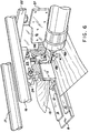
- the ultrasonic tool 4 is mounted to the carriage assembly 3 such that the blade 46 extends outwardly from the horn 51 (Fig. 8) at a low angle, preferably at angle of about 5° to 10° with respect to the horizontal, as represented by angle A in Fig. 6. It has been found that, for stock material having thicknesses of up to 0.28 cm, mounting the cutting tool 4 on the carriage assembly 3 at an angle A of about 5° to 8° results in a preferred cut of the stock material 13.
- an angle A of about 8° to 10° is preferable.
- the angle A should be set so that the width of the cut surface of the stock material is between about 1.00 cm and 2.88 cm.
- the blade 46 extends at an angle offset from an axis normal to the anvil by about 0° to 15°, and preferably at an angle of about 15°, to achieve an enhanced cutting system for most stock materials. This angle is illustrated at B in Fig. 3.
- the low angle of the blade 46 relative to the horizontal creates a beveled cut having a width of between about 1.00 cm and 2.88 cm.
- the wide cut is extremely tacky which allows the freshly cut end portion to be applied to another cut end portion to create a high strength bevel lap splice without end ply overlap.
- Conventional splicing techniques result in a tire having an inner ply wherein the two end portions have an overlapped portion, as shown indicated generally at "C" in Fig. 1A, or a crush-cut portion, as indicated generally at "D” in Fig. 1B.
- the bevelled cut provided by the present invention provides for a tire having an inner ply wherein the two portions of the material substantially seamlessly bonded together to provide a circumferentially continuous ply of stock material, as indicated generally at "E" in Fig. 1C.
- the carriage assembly 3 further includes an L-shaped shoe, indicated generally at 58, extending downwardly therefrom.
- the shoe 58 is mounted transversely behind blade 46 and thus travels immediately behind the blade 46 when the carriage assembly 3 is moving across the anvil 7.
- the shoe 58 has a substantially wedge-shaped upper surface 59 with rearwardly tapered and flared edges 60.
- Shoe surface 59 is adapted to slide between the stock material 13 and the anvil 7, thereby lifting and separating the material from the table as will be described in more detail below.
- the shoe 58 is mounted from a suspension arm 61 extending downwardly from support plate 24.
- a generally L-shape bracket 62 can be selectively longitudinally adjusted relative to the arm 61.
- the bracket 62 has a slot 63 in one leg thereof to receive bolt 64 on arm 61.
- Nut 65 on bolt 64 may be selectively drawn down against the bracket to secure the bracket in the selected longitudinal position relative to the arm 61 and carriage body 22.
- the shoe 58 is bolted to the other leg of bracket 62.
- the bottom portion 67 of the shoe 58 forms a flat surface that is adapted to slide along the top surfaces of strips 9 and 10 on anvil 7.
- the bottom portion 67 of the shoe 58 includes a generally centrally positioned guide projection 68 fixedly attached to and extending downwardly therefrom.
- the projection 68 is slidingly received in the guide channel 12 defined in the anvil 7.
- the guide projection 68 sliding in guide channel 12 maintains the alignment of the shoe and carriage assembly 3 with respect to the anvil 7 and stock material 13.
- the forward end of the guide projection 68 has a blade rest 69 mounted thereon and extending upwardly therefrom.
- the blade rest is preferably formed from a Teflon (Registered Trade Mark) material and has a pocket formed therein. As best shown in Fig. 3, the free end of the blade is received in the pocket portion of the blade rest 69.
- Both the blade 46 and the blade rest 69 are designed to move in unison across the processing table with the carriage assembly. Anchoring the end of blade 46 in the blade rest 69 prevents damaging oscillations of the free end of the blade that could result in cracking or breakage.
- the stock material 13 is brought along the processing table 2 until the desired amount of material stretches over, and is downstream of, the anvil 7.
- High frequency energy is then applied to the cutting tool 4 to produce ultrasonic waves within the crystal stack 50, horn 51 and holder 51a, (Fig. 8A), and consequently compression forces axially along the length of the blade 46.
- the carriage assembly 3 is moved across the stock material 13 with the two rollers 36, 43 leading the blade 46.
- the downward pressure of the rollers 36, 43 on the stock material 13 causes the material to be temporarily adhesively bonded to the anvil 7, particularly in the area immediately in front of the blade.
- the angle of the blade creates a bevelled cut having a width of approximately 1 cm from the edge of the cut.
- the carriage assembly 3 traverses the stock material 13 until the blade finishes its cut and reaches the opposite end.
- the blade 46 takes longer to traverse the thicker portions of the stock material than the thinner portions of the material.
- the upper surface 59 of trailing shoe 58 lifts the back portion of the cut stock material 13 away from its adhesive bond with the anvil 7.
- the surface 59 and the flared edge 60 also peels or bends the material away from the cut, as schematically illustrated in Fig. 6.
- the forward, cut length of the stock material 13 is either manually or automatically removed from the table and processed into the finished tire, while the uncut portion of the material 13 is moved down the processing table to be positioned for another cut.
- the number of stitching rollers may be increased.
- the additional rollers may, for example, extend downwardly from additional holes in support plate 24 (Fig. 1) and be located at selected positions along the strip 10 of the anvil 7.
- a series of up to seven rollers can be used, with four of the rollers positioned ahead of the blade.
- a fifth roller can be located substantially on top of the blade, and a sixth and seventh roller can be positioned behind the blade.
- At least two of the rollers, one in front of the blade and one in back of the blade, are vertically aligned with the inside edge of the back strip of the anvil.
- the leading two rollers may be toed-in, and the last two rollers may be toed-out, to stretch the stock material during the cutting process and further enhance the cutting efficiency.
- both the front and rear strips of the anvil 7 may include a number of holes (not shown) spaced therealong which are adapted to draw a vacuum therethrough.
- the holes are spaced uniformly over the length of either (or both) the front and back strips 9, 10 on the anvil 7.
- the anvil comprises a substantially T-shaped member 72 located immediately adjacent the end of the feed table 6.
- the T-shaped member 72 is adapted to be moved vertically relative to the processing table.
- the T-shaped member 72 has a channel 73 formed in the top side thereof and extending thereacross. This channel 73 receives a Lexan (Registered Trade Mark) plastic strip 74 along the cutting axis.
- channel 73 may be used as a guide channel cooperating with the projection on the carriage assembly shoe.
- the T-shape member 72 includes a stepped slot 75 in its top surface parallel to and closely spaced from channel 73.
- the stepped slot 75 extends from adjacent one end of the upper web of member 72 to adjacent its other end. The slot 75 passes entirely through the upper web of T-shaped member 72.
- Stepped slot 75 receives a T-shape stripper bar 77 therein, with the stripper bar being supported by its shoulders resting on the step of slot 75, as best shown in Fig. 10.
- Pins 78 extend downwardly from the bottom of stripper bar 77.
- the pins 78 engage a fixed stop bar 80 positioned therebelow.
- the stripper bar 77 is "elevated" relative to the upper surface of the base to strip the stock material thereon from the base.
- a spacer 100 is connected to and extends downwardly from the upstream end of the carriage body 22.
- Hanger 105 is connected to and extends downwardly from spacer 100.
- a support plate 110 is secured to and extends downwardly from the bottom of hanger 105.
- the support plate 110 can be selectively transversely adjusted relative to hanger 105.
- the hanger 105 has elongated slots 115 therein respectively receiving bolts 117 to allow selective transverse adjustment of the support plate 110 relative to the hanger 105.
- Bolts 117 have nuts (not shown) which may be selectively drawn up against the bottom of support plate 110 to secure the horizontally extending support plate 110 in the selected transverse position relative to the hanger 105.
- a horizontally and transversely extending roller support flange 120 is secured to the top surface of the carriage body 22.
- the support flange 120 may be transversely adjusted relative to the carriage body 22.
- spaced bolts 125 are received in elongated slots 127 through support flange 120.
- Bolts 125 may be selectively drawn down against flange 120 to secure the roller support flange 120 in the selected transverse position relative to the carriage body 22.
- the support flange 120 has a downwardly extending first threaded shaft 130 received in a bore at one end of the support flange.
- a nut 135 can be threaded onto the threaded shaft 130 and bears against the upper surface of support flange 120. The position of the nut controls the vertical position of the shaft 130 relative to support flange 120.
- Shaft 130 extends downwardly and has a roller support bracket, shown generally at 140, mounted to its lower end.
- a spring 145 may be located on shaft 130 between support flange 120 and roller support bracket 140. Spring 145 biases the roller support bracket away from support flange 120 to bring nut 135 into engagement with support bracket 120.
- Roller support bracket 140 further includes two downwardly extending parallel arms 147, 148 as shown in Figs. 11 and 13, respectively, having a roller shaft, indicated generally at 150, extending therebetween.
- Roller shaft 150 extends through aligned mounting holes in the arms of roller support bracket 140.
- Shaft 150 is secured to the respective arms by nuts 154 threaded onto the opposite free ends of shaft 150.
- the shaft is above and in parallel relationship to strip 10 of anvil 7.
- a wide roller 155 is rotatably mounted on shaft 150 and provides downward pressure to the stock material.
- roller support bracket 140 is vertically guided to maintain proper alignment with the anvil 7.
- guide stud 168a extends longitudinally through support plate 110.
- the outer ends of the guide stud are received in a vertically extending slot 165, 166, respectively, in arms 147 or 148.
- a spacer washer 170 is received on one end of guide stud 168a between the outside edge of downwardly extending arm 148 and the one head of stud 168a.
- spacer washer 169 is received on the other end of stud 168a between the outside edge of downwardly extending arm 147, and a second head of stud 168a.
- spacer 171 is received on stud 168a and extends between the support plate 110 and the inside edge of downwardly extending arm 147.
- the roller support bracket 140 is biased downwardly toward anvil 7 by spring 145.
- the spring is adapted to maintain a predetermined downward pressure on the anvil 7, yet be flexible enough to allow the roller support bracket, and hence shaft 130 and nut 135, to be raised to insert the stock material between the roller and the anvil.
- a second roller 43 is mounted to and extends downwardly from the support plate 110.
- the construction of second roller assembly in this embodiment is substantially the same as the construction described in connection with the first embodiment.
- an L-shaped shoe is mounted from a suspension arm 185 by a plate 190 (Fig. 13).
- Suspension arm 185 is received in groove 186 of hanger 105, extends downwardly therefrom and may be adjusted longitudinally relative to hanger 105.
- Plate 190 can be fastened to the suspension arm 185 by conventional fasteners, such as by nuts and bolts.
- spaced bolts 192 pass through bores in plate 190 into tapped holes in suspension arm 185 in alignment therewith.
- the shoe 180 can be mounted to the bottom of plate 190.
- plate 190 has a plurality of elongated slots 194 passing therethrough.
- Bolts 193 pass through slots 194 into tapped holes in the vertical arm of shoe 180.
- the slots 194 allow the shoe to be vertically adjusted relative to the plate 190. This vertical adjustment may be closely controlled by an eccentric adjustment mechanism.
- the eccentric adjustment mechanism includes an elliptical drive shaft 195 that extends through an oversized bore in plate 190 into a circular opening 198 in the vertical leg of shoe 180. As the elliptical drive shaft is turned, the surface thereof cammingly engages the opening 198 to raise or lower the shoe 180. When the proper shoe position is obtained (preferably providing a clearance of approximately 0.08mm (3/1000 of an inch) between the bottom of the shoe and the anvil), the shoe-is tightly secured.
- the elliptical drive shaft 195 has a threaded shank 196 on its downstream end.
- a washer 197 is positioned on shank 196.
- the washer is drawn against the plate 190 by nuts 199.
- the bolts 193 are then tightened against the plate to complete the rigid mounting of shoe 180 to plate 190 in its selected vertical position.
- the shoe 180 includes a bottom portion, indicated generally at 200 and shown in Fig. 11. This shoe is substantially the same in design and function as the bottom portion 67 of shoe 58 in the first embodiment as described herein.
- the bottom portion 200 of shoe 180 includes a wedge shape surface 59, a blade rest 69 and a guide projection 68 extending therebetween and connected thereto.
- the bottom portion has a roller assembly 205 attached thereto.
- Roller assembly 205 preferably includes, for example, three rollers 205a, 205b, 205c, mounted within a bracket 207. Rollers 205a-205c extend in a co-planar relationship along the side of the bottom portion 200 of shoe 180. The rollers increase in diameter as they get closer to the wedge shape surface 59.
- Each roller has an axle extending therethrough which is rotatably attached to opposing sides of bracket 207.
- the bracket 207 in turn is attached to the side of the bottom portion 200.
- the three rollers are adapted to facilitate the removal of the stock material from its adhesive bond with the anvil.
- the stock material tends to removably adhere to the rollers and consequently "ride up” the rollers and onto the shoe during rotation of the rollers.
- the material 13 is easily removed by the shoe passing between the anvil and the material.
- a blade stabilization assembly shown generally at 209, having spring-loaded teflon button 210 can be included with the carriage assembly to minimize the possibility of the blade either cracking or breaking.
- the teflon button 210 is adapted to engage the top surface of blade 46 to damp out potentially damaging vertical vibrations of the blade.
- the teflon button 210 extends through a bore in bracket 215 and is secured thereto, as shown at 217.
- Bracket 215 is pivotally connected to holder 219, which in turn is removably attached to shoe 180 by bolts 220.
- Holder 219 includes an outwardly extending tongue member 225.
- Bracket 215 has a yoke comprising two arms 226, 227, which extend along opposite sides of tongue member 225.
- the arms 226, 227 are pivotally connected to the outwardly extending tongue member 225 by a horizontally extending pivot bolt 230.
- Bolt 230 is received in a fist set of cooperating and aligned holes in arms 226, 227 and member 225.
- a second set of cooperating holes are provided in arms 226, 227 and member 225 to maintain the horizontal alignment of the bracket 215 with respect to the anvil, and to maintain a predetermined downwardly directed pressure on the blade.
- a key pin 232 is adapted to be received in the second set of holes when bracket 215 and member 225 are horizontally aligned.
- bolt 230 and pin 232 maintain the horizontal alignment of the bracket 215 with the member 225, and hence the anvil 7.
- Pin 232 is adapted to be removed to allow the bracket 215 to be pivoted around pivot bolt 230.
- the button 210 can thus be pivoted away from its engagement with the blade 46 to facilitate repairs to the blade or to the teflon button. Accordingly, when key pin 232 is inserted within the second set of holes in arms 226, 227 and member 225, the spring-loaded teflon button 210 is adapted to contact blade 46 and limit the vertical vibrations of the oscillating blade, to thereby increase the precision of the cut. Moreover, the button 210 increases the life of the blade by minimizing vibrations that can cause metal fatigue.
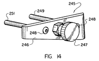
- the ultrasonic cutting tool may include a quick connect system, indicated generally at 240, wherein a failed transducer can be quickly replaced, or an operating transducer can be accurately adjusted to a selected angle at a location separate from the cutting system, and then quickly fitted into place on the carriage body 22.
- the quick connect system includes a disconnect member, indicated generally at 245.
- the disconnect member 245 includes plate 246, knob 247 and shafts 249, 251.
- Knob 247 extends outwardly from the front side of plate 246 and is used to turn a threaded bolt on the other side of the plate 246.
- Shafts 249, 251 are attached to the back side of plate 246 with bolts 248 and extend outwardly therefrom.
- a modified bracket 255 having a substantially I-beam shape, is secured to carriage body 22 by bolts 260, and extends downwardly therefrom. Further, mounting flange 261 is secured to the bottom web of modified bracket 255 by bolts 262. Mounting flange 261 extends downwardly from bracket 255. Mounting flange 261 includes an inverted groove, indicated generally at 263, extending along the length of the flange. Groove 263 is adapted to receive a tongue 264 on support collar 265.
- the transducer housing 48 is fitted within collar 265 and the tongue 264 of the collar 265 is received within the groove in flange 261.
- the knob 247 is turned to advance the threaded bolt into a tapped hole in the mounting flange 261 to hold the plate 246 in mounted position on mounting flange 261.
- the shafts 249, 251 of disconnect member 245 are received in cooperating bores in mounting flange 261 and tongue 264 to thereby support the transducer housing.
- Disconnect member 245 may be removed from flange 261 by reverse rotating knob 247 to remove shafts 249, 251 from the aligned bores in the tongue and mounting member. Once disconnect member 245 is removed, collar 265 can be removed from the carriage and a new collar and transducer attached. Consequently, disconnect member 245 allows the quick change of transducers for use with the ultrasonic cutting system.
- a low angle cut of the stock material can be achieved.
- the blade traverses the material without the material moving or vibrating, thereby decreasing the cutting time and increasing the quality of the cut.
- the material can be cut at a low angle to increase the surface area of the cut portion and to allow the cut surface to be substantially seamlessly bevel lap spliced to the cut surface at the other end of the stock material in the tyre building process.
- the substantially seamless splice reduces the radial forces on the splice, improves the balance of the tyre, and reduces tyre cure time. Additionally, the material savings in eliminating the end ply overlap reduces the overall cost of the tyre.
Landscapes
- Engineering & Computer Science (AREA)
- Mechanical Engineering (AREA)
- Textile Engineering (AREA)
- Life Sciences & Earth Sciences (AREA)
- Forests & Forestry (AREA)
- Perforating, Stamping-Out Or Severing By Means Other Than Cutting (AREA)
- Nonmetal Cutting Devices (AREA)
- Tyre Moulding (AREA)
Claims (7)
- Ultraschallschneidvorrichtung (1) für Lagermaterial, mit einem Amboß (7), Einrichtungen (36. 43), um das Lagermaterial (13) zeitweise an dem Amboß zu sichern, einem Laufwagenaufbau (3), der quer über die Breite des Amboßes hinweg bewegbar ist, ein Ultraschallschneidwerkzeug (4) welches an dem Laufwagen montiert ist, wobei das Schneidwerkzeug ein mechanisch angekoppeltes Blatt (46) hat, wobei das Blatt unter Absprechen auf Ultraschallenergie, welche in Längsrichtung durch das Blatt hindurchläuft, mitschwingt,
wobei das Ultraschallschneidwerkzeug (4) bezüglich des Ambosses (7) derart montiert ist, daß sich das Blatt (46) für Lager- bzw. Bahnmaterial unter 0,49 cm Dicke unter einem Winkel von 5 - 10 ° bezüglich der Horizontalen erstreckt oder, für Lager- bzw. Bahnmaterial mit einer Dicke von mehr als 0,49 cm, unter einem solchen Winkel erstreckt, daß die Schneidfläche des Lager- bzw. Bahnmaterials eine Breite zwischen etwa 1,00 und etwa 2,88 cm hat, und
wobei dann, wenn der Laufwagenaufbahn (3) quer über den Amboß hinwegläuft, das Blatt (6) quer durch das Lager- bzw. Bahnmaterial (13) hindurchschneidet,
dadurch gekennzeichnet, daß die Vorrichtung eine Einrichtung (58) aufweist, die relativ zu dem Amboß gleitbar und in der Lage ist, mit dem Bahnmaterial, welches an einer Stelle hinter dem Blatt (46) angeordnet ist, in Eingriff zu treten, um das Bahnmaterial (13) von dem Amboß (7) zu trennen, nach dem das Blatt das Bahn-material durchschnitten hat. - Ultraschallschneidvorrichtung für Bahnmaterial nach Anspruch 1, wobei die Einrichtung (36, 43) für das zeitweise adhäsive Sichern des Bahnmaterials zumindest eine Andruckrolle (36, 43) aufweist, die auf dem Laufwagenaufbau (3) montiert ist, um das Bahnmaterial (13) an dem Amboß (7) an einer Stelle vor dem Blatt (46) zu sichern bzw. zu befestigen.
- Ultraschallschneidvorrichtung für Bahnmaterial nach einem der vorstehenden Ansprüche, wobei der Amboß (7) ein Vakuum einschließt, um zeitweise das Bahnmaterial (13) an dem Amboß (7) zu sichern.
- Utraschallschneidvorrichtung für Bahnmaterial nach einem der vorstehenden Ansprüche, wobei das Blatt (46) um einem Winkel von etwa 0° bis 15° relativ zu einer senkrecht zu dem Amboß (7) verlaufenden Achse versetzt ist.
- Verfahren zum Ultraschallschneiden von Lager- bzw. Bahnmaterial mit den Schritten:zeitweises Sichern des Lager- bzw. Bahnmaterials an einem Amboß (7),mechanisches Ankoppeln eines Blattes bzw. einer Schneide (46) an einen Ultraschallwandler (47), um ein Ultraschallschneidwerkzeug (4) zu bilden,Montieren des Ultraschallschneidwerkzeuges an einem Laufwagenaufbau (3), in Resonanz Versetzen des Blattes (46) mit Ultraschallenergie, welche in Längsrichtung durch dieses hindurchläuft,Bewegen des Laufwagenaufbaus (3) quer über die Breite des Bahnmaterials (13), undSchneiden des Bahnmaterials (13) mit dem Blatt (46), während der Laufwagenaufbau sich quer über die Breite des Bahnmaterials (13) hinwegbewegt,wobei der Schritt des Schneidens des Bahnmaterials (13) mit einem Messer (46) das Schneiden des Bahnmaterials (13) für ein Bahnmaterial unter 0,49 cm Dicke unter einem Winkel von 5 - 10° relativ zu der Horizontalen oder, für Material einer Dicke von mehr als 0,49 cm, unter einem solchen Winkel aufweist, daß die Schneidfläche des Bahnmaterials eine Breite zwischen etwa 1,0 cm und 2,8 cm hat,
gekennzeichnet durch Einschließen des Schrittes, daß eine Einrichtung (58), welche relativ zu dem Amboß (7) gleitbar ist, mit dem Bahnmaterial, welches an einer Stelle hinter dem Blatt angeordnet ist, in Eingriff tritt, um das Bahnmaterial von dem Amboß (7) zu trennen, nachdem das Blatt das Bahnmaterial geschnitten hat. - Verfahren zum Ultraschallschneiden von Bahnmaterial nach Anspruch 5, wobei der Schritt des Schneidens des Bahnmaterials (13) mit einem Blatt (46) das Schneiden des Bahnmaterials (13) unter einem Versatzwinkel von etwa 0 - 15 ° relativ zu einer Achse senkrecht zu dem Amboß (7) einschließt.
- Verfahren zum Ultraschallschneiden von Bahnmaterial nach Anspruch 5 oder 6, einschließlich eines weiteren Schrittes des Dämpfens von vertikalen Schwingungen des Blattes (46).
Applications Claiming Priority (2)
| Application Number | Priority Date | Filing Date | Title |
|---|---|---|---|
| US07/606,715 US5265508A (en) | 1990-10-31 | 1990-10-31 | Ultrasonic cutting system for stock material |
| US606715 | 1990-10-31 |
Publications (3)
| Publication Number | Publication Date |
|---|---|
| EP0483973A2 EP0483973A2 (de) | 1992-05-06 |
| EP0483973A3 EP0483973A3 (en) | 1992-10-28 |
| EP0483973B1 true EP0483973B1 (de) | 1996-11-20 |
Family
ID=24429162
Family Applications (1)
| Application Number | Title | Priority Date | Filing Date |
|---|---|---|---|
| EP91308908A Expired - Lifetime EP0483973B1 (de) | 1990-10-31 | 1991-09-27 | Ultrasonisches Schneidverfahren |
Country Status (6)
| Country | Link |
|---|---|
| US (1) | US5265508A (de) |
| EP (1) | EP0483973B1 (de) |
| JP (1) | JP2622447B2 (de) |
| CA (1) | CA2049659C (de) |
| DE (1) | DE69123222T2 (de) |
| MX (1) | MX9101849A (de) |
Families Citing this family (35)
| Publication number | Priority date | Publication date | Assignee | Title |
|---|---|---|---|---|
| FR2689436B1 (fr) * | 1992-04-07 | 1996-05-24 | Linder Ets | Procede et dispositif pour la coupe de materiaux textiles par ultrasons. |
| JP2645798B2 (ja) * | 1993-07-16 | 1997-08-25 | 三ツ星ベルト株式会社 | ゴム成形体の切断装置およびその切断方法 |
| EP0865882A3 (de) * | 1997-03-20 | 1999-05-06 | Cooper Tire & Rubber Company | Ultraschallvorrichtung zum gehrungsgerechten Schneiden von unvulkanisiertem Kautschuk |
| US6510773B1 (en) | 1998-10-20 | 2003-01-28 | The Goodyear Tire And Rubber Company | Method and apparatus for cutting elastomeric materials |
| AU2800799A (en) * | 1999-03-03 | 2000-09-21 | Goodyear Tire And Rubber Company, The | Forming splice joints for elastomeric materials |
| US6592704B1 (en) | 1999-03-03 | 2003-07-15 | The Goodyear Tire & Rubber Company | Forming splice joints for elastomeric materials |
| US6755105B2 (en) * | 2001-06-01 | 2004-06-29 | The Goodyear Tire & Rubber Company | Method and apparatus for cutting elastomeric materials and the article made by the method |
| US6790301B2 (en) | 2001-10-15 | 2004-09-14 | The Goodyear Tire And Rubber Company | Method and apparatus for making a tread-belt assembly |
| DE10210075B4 (de) * | 2002-03-08 | 2008-04-30 | Stapla Ultraschall-Technik Gmbh | Vorrichtung zum Abdichten und Trennen eines Rohrabschnitts |
| US20050081692A1 (en) * | 2003-10-20 | 2005-04-21 | Kraft Foods Holdings, Inc. | Ultrasonic slitter |
| US8495943B2 (en) | 2004-04-22 | 2013-07-30 | The Boeing Company | Anvil for supporting cuts in sheet and roll stock |
| DE102004022313B3 (de) * | 2004-05-04 | 2005-10-20 | Stapla Ultraschalltechnik Gmbh | Vorrichtung und Verfahren zum fluiddichten Dichtschweißen eines Rohrabschnittes |
| US20060070504A1 (en) * | 2004-10-01 | 2006-04-06 | Downing Daniel R | Apparatus for cutting elastomeric materials |
| EP1799408B1 (de) * | 2004-10-08 | 2012-11-14 | Compagnie Generale Des Etablissements Michelin | Vormontierte kautschukschneideprodukte |
| US7524398B2 (en) * | 2004-12-23 | 2009-04-28 | The Goodyear Tire & Rubber Company | Apparatus for making tire components, and a tire |
| US20060137814A1 (en) * | 2004-12-23 | 2006-06-29 | Downing Daniel R | Method for making reinforced elastomeric materials |
| US20060137804A1 (en) * | 2004-12-23 | 2006-06-29 | Downing Daniel R | Method for making tire ply |
| US7455002B2 (en) * | 2004-12-23 | 2008-11-25 | The Goodyear Tire & Rubber Company | Method for cutting elastomeric materials and the article made by the method |
| US8561511B2 (en) * | 2004-12-23 | 2013-10-22 | The Goodyear Tire & Rubber Company | Anvil with vacuum width adjustment |
| US20060229184A1 (en) * | 2005-04-07 | 2006-10-12 | Hewlett-Packard Development Company, L.P. | Creaser |
| US8166857B2 (en) | 2005-07-01 | 2012-05-01 | Hewlett-Packard Development Company, L.P. | Perforator |
| JP2007038367A (ja) * | 2005-08-04 | 2007-02-15 | Seiko Instruments Inc | シート材切断ユニット、および印刷装置 |
| JP5020962B2 (ja) * | 2006-10-17 | 2012-09-05 | 一正 大西 | 円盤状の切削工具及び切削装置 |
| DE102008056372A1 (de) * | 2008-10-27 | 2010-04-29 | Harburg-Freudenberger Maschinenbau Gmbh | Verfahren und Vorrichtung zum Schneiden |
| US20150007704A1 (en) * | 2013-07-08 | 2015-01-08 | Branson Ultrasonics Corporation | Ultrasonic steel horn for tire cutting and method of manufacturing |
| CN106541434B (zh) * | 2016-11-30 | 2018-06-22 | 上海荣南科技有限公司 | 一种天窗密封条精切机机械装置 |
| JP6490135B2 (ja) * | 2017-04-07 | 2019-03-27 | 株式会社島精機製作所 | 切断装置及びこれを備えた延反機 |
| US11186004B2 (en) | 2017-10-30 | 2021-11-30 | The Boeing Company | Stabilizing shoe, manufacturing apparatus, and manufacturing method |
| JP7218056B2 (ja) * | 2019-02-20 | 2023-02-06 | 株式会社ディスコ | チップ及び枠体の少なくともいずれかを製造する方法 |
| CN110126006A (zh) * | 2019-04-30 | 2019-08-16 | 爱西卡(广州)科技有限公司 | 一种基于云服务管理的嵌入式智能切割系统 |
| US11052494B1 (en) | 2020-01-07 | 2021-07-06 | The Boeing Company | Methods and apparatus for semi-automated tack welding of plies of a thermoplastic composite layup |
| CN111390590A (zh) * | 2020-04-16 | 2020-07-10 | 江苏长风海洋装备制造有限公司 | 风电塔筒钢板坡口切割装置 |
| US11858160B2 (en) | 2021-09-09 | 2024-01-02 | Lockheed Martin Corporation | Ultrasonic cutting system and method |
| NL2031212B1 (en) * | 2022-03-09 | 2023-09-18 | Vmi Holland Bv | Cutting device and method for cutting a tire component |
| US20240181725A1 (en) * | 2022-12-02 | 2024-06-06 | The Boeing Company | Trimming and Scrap Removal System for Composite Structures |
Family Cites Families (17)
| Publication number | Priority date | Publication date | Assignee | Title |
|---|---|---|---|---|
| US3246551A (en) * | 1964-02-27 | 1966-04-19 | Goodyear Tire & Rubber | Bias-cutting machine |
| JPS583850A (ja) * | 1981-06-30 | 1983-01-10 | Toyo Tire & Rubber Co Ltd | タイヤバンドの成形方法 |
| JPS58203033A (ja) * | 1982-05-24 | 1983-11-26 | Bridgestone Corp | 未加硫ゴムシ−ト切断装置 |
| US4858505A (en) * | 1983-05-09 | 1989-08-22 | The Firestone Tire & Rubber Company | Pivotable knife |
| US4567797A (en) * | 1984-01-30 | 1986-02-04 | Folk Donald C | Ultrasonic cutting apparatus and methods |
| DE3403710C1 (de) * | 1984-02-03 | 1985-07-18 | Carl Schmale GmbH & Co KG, 4434 Ochtrup | Vorrichtung zum fortlaufenden Laengstrennen von Gewebebahnen |
| US4623420A (en) * | 1985-06-06 | 1986-11-18 | Branson Ultrasonics Corporation | Anvil for ultrasonic slitting apparatus |
| IT1189649B (it) * | 1986-04-08 | 1988-02-04 | Firestone Int Dev Spa | Dispositivo per il taglio trasversale di strisce di materiale deformabile |
| US4711693A (en) * | 1986-07-07 | 1987-12-08 | Branson Ultrasonics Corp. | Anvil for ultrasonic slitting apparatus |
| US4813319A (en) * | 1987-04-01 | 1989-03-21 | The Firestone Tire & Rubber Company | Method and apparatus for transversely cutting strips of deformable material |
| US4792372A (en) * | 1987-07-24 | 1988-12-20 | General Tire, Inc. | Automatic sidewall servicer |
| US5007315A (en) * | 1987-07-24 | 1991-04-16 | General Tire, Inc. | Automatic sidewall servicer |
| JPH07115426B2 (ja) * | 1987-07-27 | 1995-12-13 | 株式会社ブリヂストン | 帯状部材の貼付け方法および装置 |
| NL8800077A (nl) * | 1988-01-14 | 1989-08-01 | Vmi Epe Holland | Inrichting voor het doorsnijden van een strook ongevulcaniseerde rubber. |
| IT1230916B (it) * | 1988-06-27 | 1991-11-08 | Central Glass Co Ltd | Dispositivo e metodo per tagliare parte di bordo superfluo di interstrato di vetro laminato |
| DE8812461U1 (de) * | 1988-10-03 | 1990-02-01 | ETS - Elektro-thermische Schneidwerkzeug GmbH, 8050 Freising | Vorrichtung zum gehrungsgerechten Schneiden von Stoßkanten an Gummiplatten |
| DE9003873U1 (de) * | 1990-04-03 | 1990-07-05 | Post, Gerhard, 2106 Bendestorf | Holzhaus im Blockhausstil |
-
1990
- 1990-10-31 US US07/606,715 patent/US5265508A/en not_active Expired - Fee Related
-
1991
- 1991-08-21 CA CA002049659A patent/CA2049659C/en not_active Expired - Fee Related
- 1991-09-27 DE DE69123222T patent/DE69123222T2/de not_active Expired - Fee Related
- 1991-09-27 EP EP91308908A patent/EP0483973B1/de not_active Expired - Lifetime
- 1991-10-30 MX MX9101849A patent/MX9101849A/es not_active IP Right Cessation
- 1991-10-31 JP JP3286335A patent/JP2622447B2/ja not_active Expired - Fee Related
Also Published As
| Publication number | Publication date |
|---|---|
| CA2049659C (en) | 1996-05-07 |
| DE69123222D1 (de) | 1997-01-02 |
| EP0483973A2 (de) | 1992-05-06 |
| DE69123222T2 (de) | 1997-04-30 |
| EP0483973A3 (en) | 1992-10-28 |
| CA2049659A1 (en) | 1992-05-01 |
| US5265508A (en) | 1993-11-30 |
| JPH04300199A (ja) | 1992-10-23 |
| MX9101849A (es) | 1992-09-01 |
| JP2622447B2 (ja) | 1997-06-18 |
Similar Documents
| Publication | Publication Date | Title |
|---|---|---|
| EP0483973B1 (de) | Ultrasonisches Schneidverfahren | |
| US7526986B2 (en) | Method for cutting elastomeric materials | |
| US4572046A (en) | Pivot mounted cutting knife | |
| EP1674252A1 (de) | Verfahren zum Schneiden von elastomeren Materialien und damit hergestelltes Segment | |
| PL179313B1 (pl) | S p o só b ciecia laminatu i urzadzenie do ciecia laminatu PL PL | |
| US5632831A (en) | System and method for cutting and splicing polymeric webs | |
| US6575064B2 (en) | Method and apparatus for cutting elastomeric materials | |
| EP0125882A2 (de) | Vorrichtung zum Aufbringen von Lagen | |
| US7431786B2 (en) | Apparatus and method for affixing tire component member | |
| US3607576A (en) | Wire overhead machine | |
| JP2572196B2 (ja) | ゴムシートのジョイント方法及びその装置 | |
| EP0436065B1 (de) | Verfahren und Vorrichtung zum automatischen Verkleben zwischen einer Folie und einem Substrat, und zum Schneiden der Folie | |
| JP4493163B2 (ja) | シート状未加硫ゴム材料の接合システム | |
| CN117381900A (zh) | 裁切装置 | |
| JPH10156965A (ja) | 未加硫ゴムシートの貼付け方法及びその装置 | |
| EP0125146B1 (de) | Zentriervorrichtung mit Rollen | |
| JPS6319356Y2 (de) | ||
| US6062552A (en) | Preassembly cutter clamp for use during tire production | |
| JP2624606B2 (ja) | ラバーコンポーネントカッター | |
| CN221439916U (zh) | 一种断料带输送装置及断料带制片设备 | |
| KR102189706B1 (ko) | 지관 분리를 위한 테이프 절단장치 | |
| JP3353996B2 (ja) | 帯状部材の供給装置 | |
| JPH09183158A (ja) | 円筒状ゴムシートの製造方法およびその装置 | |
| CN118514372A (zh) | 一种二次法轮胎成型机带束输送裁断装置 | |
| JPH10309693A (ja) | 未加硫ゴム材料用の超音波式切削具 |
Legal Events
| Date | Code | Title | Description |
|---|---|---|---|
| PUAI | Public reference made under article 153(3) epc to a published international application that has entered the european phase |
Free format text: ORIGINAL CODE: 0009012 |
|
| AK | Designated contracting states |
Kind code of ref document: A2 Designated state(s): BE DE FR GB IT LU NL |
|
| PUAL | Search report despatched |
Free format text: ORIGINAL CODE: 0009013 |
|
| AK | Designated contracting states |
Kind code of ref document: A3 Designated state(s): BE DE FR GB IT LU NL |
|
| 17P | Request for examination filed |
Effective date: 19930408 |
|
| 17Q | First examination report despatched |
Effective date: 19940518 |
|
| GRAG | Despatch of communication of intention to grant |
Free format text: ORIGINAL CODE: EPIDOS AGRA |
|
| GRAH | Despatch of communication of intention to grant a patent |
Free format text: ORIGINAL CODE: EPIDOS IGRA |
|
| GRAH | Despatch of communication of intention to grant a patent |
Free format text: ORIGINAL CODE: EPIDOS IGRA |
|
| GRAA | (expected) grant |
Free format text: ORIGINAL CODE: 0009210 |
|
| AK | Designated contracting states |
Kind code of ref document: B1 Designated state(s): BE DE FR GB IT LU NL |
|
| ITF | It: translation for a ep patent filed | ||
| ET | Fr: translation filed | ||
| REF | Corresponds to: |
Ref document number: 69123222 Country of ref document: DE Date of ref document: 19970102 |
|
| PLBE | No opposition filed within time limit |
Free format text: ORIGINAL CODE: 0009261 |
|
| STAA | Information on the status of an ep patent application or granted ep patent |
Free format text: STATUS: NO OPPOSITION FILED WITHIN TIME LIMIT |
|
| 26N | No opposition filed | ||
| PGFP | Annual fee paid to national office [announced via postgrant information from national office to epo] |
Ref country code: BE Payment date: 19981012 Year of fee payment: 8 |
|
| PG25 | Lapsed in a contracting state [announced via postgrant information from national office to epo] |
Ref country code: BE Free format text: LAPSE BECAUSE OF NON-PAYMENT OF DUE FEES Effective date: 19990930 |
|
| BERE | Be: lapsed |
Owner name: GENERAL TIRE INC. Effective date: 19990930 |
|
| REG | Reference to a national code |
Ref country code: GB Ref legal event code: IF02 |
|
| PGFP | Annual fee paid to national office [announced via postgrant information from national office to epo] |
Ref country code: NL Payment date: 20040829 Year of fee payment: 14 |
|
| PGFP | Annual fee paid to national office [announced via postgrant information from national office to epo] |
Ref country code: FR Payment date: 20040920 Year of fee payment: 14 |
|
| PGFP | Annual fee paid to national office [announced via postgrant information from national office to epo] |
Ref country code: GB Payment date: 20040922 Year of fee payment: 14 |
|
| PGFP | Annual fee paid to national office [announced via postgrant information from national office to epo] |
Ref country code: LU Payment date: 20041004 Year of fee payment: 14 |
|
| PGFP | Annual fee paid to national office [announced via postgrant information from national office to epo] |
Ref country code: DE Payment date: 20041102 Year of fee payment: 14 |
|
| PG25 | Lapsed in a contracting state [announced via postgrant information from national office to epo] |
Ref country code: IT Free format text: LAPSE BECAUSE OF NON-PAYMENT OF DUE FEES Effective date: 20050927 Ref country code: GB Free format text: LAPSE BECAUSE OF NON-PAYMENT OF DUE FEES Effective date: 20050927 |
|
| PG25 | Lapsed in a contracting state [announced via postgrant information from national office to epo] |
Ref country code: LU Free format text: LAPSE BECAUSE OF NON-PAYMENT OF DUE FEES Effective date: 20050930 |
|
| PG25 | Lapsed in a contracting state [announced via postgrant information from national office to epo] |
Ref country code: NL Free format text: LAPSE BECAUSE OF NON-PAYMENT OF DUE FEES Effective date: 20060401 Ref country code: DE Free format text: LAPSE BECAUSE OF NON-PAYMENT OF DUE FEES Effective date: 20060401 |
|
| GBPC | Gb: european patent ceased through non-payment of renewal fee |
Effective date: 20050927 |
|
| PG25 | Lapsed in a contracting state [announced via postgrant information from national office to epo] |
Ref country code: FR Free format text: LAPSE BECAUSE OF NON-PAYMENT OF DUE FEES Effective date: 20060531 |
|
| NLV4 | Nl: lapsed or anulled due to non-payment of the annual fee |
Effective date: 20060401 |
|
| REG | Reference to a national code |
Ref country code: FR Ref legal event code: ST Effective date: 20060531 |