EP0484035B1 - Verfahren und Vorrichtung zur Änderung des Querschnittes eines Körpers - Google Patents
Verfahren und Vorrichtung zur Änderung des Querschnittes eines Körpers Download PDFInfo
- Publication number
- EP0484035B1 EP0484035B1 EP91309752A EP91309752A EP0484035B1 EP 0484035 B1 EP0484035 B1 EP 0484035B1 EP 91309752 A EP91309752 A EP 91309752A EP 91309752 A EP91309752 A EP 91309752A EP 0484035 B1 EP0484035 B1 EP 0484035B1
- Authority
- EP
- European Patent Office
- Prior art keywords
- regions
- torch
- excess
- speed
- source
- Prior art date
- Legal status (The legal status is an assumption and is not a legal conclusion. Google has not performed a legal analysis and makes no representation as to the accuracy of the status listed.)
- Expired - Lifetime
Links
Images

Classifications
-
- C—CHEMISTRY; METALLURGY
- C03—GLASS; MINERAL OR SLAG WOOL
- C03B—MANUFACTURE, SHAPING, OR SUPPLEMENTARY PROCESSES
- C03B37/00—Manufacture or treatment of flakes, fibres, or filaments from softened glass, minerals, or slags
- C03B37/01—Manufacture of glass fibres or filaments
- C03B37/012—Manufacture of preforms for drawing fibres or filaments
- C03B37/01205—Manufacture of preforms for drawing fibres or filaments starting from tubes, rods, fibres or filaments
- C03B37/01225—Means for changing or stabilising the shape, e.g. diameter, of tubes or rods in general, e.g. collapsing
- C03B37/01228—Removal of preform material
-
- C—CHEMISTRY; METALLURGY
- C03—GLASS; MINERAL OR SLAG WOOL
- C03B—MANUFACTURE, SHAPING, OR SUPPLEMENTARY PROCESSES
- C03B23/00—Re-forming shaped glass
- C03B23/04—Re-forming tubes or rods
- C03B23/043—Heating devices specially adapted for re-forming tubes or rods in general, e.g. burners
-
- C—CHEMISTRY; METALLURGY
- C03—GLASS; MINERAL OR SLAG WOOL
- C03B—MANUFACTURE, SHAPING, OR SUPPLEMENTARY PROCESSES
- C03B23/00—Re-forming shaped glass
- C03B23/04—Re-forming tubes or rods
- C03B23/057—Re-forming tubes or rods by fusing, e.g. for flame sealing
-
- C—CHEMISTRY; METALLURGY
- C03—GLASS; MINERAL OR SLAG WOOL
- C03B—MANUFACTURE, SHAPING, OR SUPPLEMENTARY PROCESSES
- C03B29/00—Reheating glass products for softening or fusing their surfaces; Fire-polishing; Fusing of margins
- C03B29/02—Reheating glass products for softening or fusing their surfaces; Fire-polishing; Fusing of margins in a discontinuous way
-
- C—CHEMISTRY; METALLURGY
- C03—GLASS; MINERAL OR SLAG WOOL
- C03B—MANUFACTURE, SHAPING, OR SUPPLEMENTARY PROCESSES
- C03B37/00—Manufacture or treatment of flakes, fibres, or filaments from softened glass, minerals, or slags
- C03B37/01—Manufacture of glass fibres or filaments
- C03B37/012—Manufacture of preforms for drawing fibres or filaments
- C03B37/01205—Manufacture of preforms for drawing fibres or filaments starting from tubes, rods, fibres or filaments
- C03B37/01225—Means for changing or stabilising the shape, e.g. diameter, of tubes or rods in general, e.g. collapsing
- C03B37/01257—Heating devices therefor
-
- C—CHEMISTRY; METALLURGY
- C03—GLASS; MINERAL OR SLAG WOOL
- C03B—MANUFACTURE, SHAPING, OR SUPPLEMENTARY PROCESSES
- C03B37/00—Manufacture or treatment of flakes, fibres, or filaments from softened glass, minerals, or slags
- C03B37/01—Manufacture of glass fibres or filaments
- C03B37/012—Manufacture of preforms for drawing fibres or filaments
- C03B37/014—Manufacture of preforms for drawing fibres or filaments made entirely or partially by chemical means, e.g. vapour phase deposition of bulk porous glass either by outside vapour deposition [OVD], or by outside vapour phase oxidation [OVPO] or by vapour axial deposition [VAD]
- C03B37/01446—Thermal after-treatment of preforms, e.g. dehydrating, consolidating, sintering
-
- C—CHEMISTRY; METALLURGY
- C03—GLASS; MINERAL OR SLAG WOOL
- C03B—MANUFACTURE, SHAPING, OR SUPPLEMENTARY PROCESSES
- C03B37/00—Manufacture or treatment of flakes, fibres, or filaments from softened glass, minerals, or slags
- C03B37/01—Manufacture of glass fibres or filaments
- C03B37/012—Manufacture of preforms for drawing fibres or filaments
- C03B37/014—Manufacture of preforms for drawing fibres or filaments made entirely or partially by chemical means, e.g. vapour phase deposition of bulk porous glass either by outside vapour deposition [OVD], or by outside vapour phase oxidation [OVPO] or by vapour axial deposition [VAD]
- C03B37/01466—Means for changing or stabilising the diameter or form of tubes or rods
-
- C—CHEMISTRY; METALLURGY
- C03—GLASS; MINERAL OR SLAG WOOL
- C03B—MANUFACTURE, SHAPING, OR SUPPLEMENTARY PROCESSES
- C03B37/00—Manufacture or treatment of flakes, fibres, or filaments from softened glass, minerals, or slags
- C03B37/01—Manufacture of glass fibres or filaments
- C03B37/012—Manufacture of preforms for drawing fibres or filaments
- C03B37/014—Manufacture of preforms for drawing fibres or filaments made entirely or partially by chemical means, e.g. vapour phase deposition of bulk porous glass either by outside vapour deposition [OVD], or by outside vapour phase oxidation [OVPO] or by vapour axial deposition [VAD]
- C03B37/0148—Means for heating preforms during or immediately prior to deposition
-
- C—CHEMISTRY; METALLURGY
- C03—GLASS; MINERAL OR SLAG WOOL
- C03B—MANUFACTURE, SHAPING, OR SUPPLEMENTARY PROCESSES
- C03B37/00—Manufacture or treatment of flakes, fibres, or filaments from softened glass, minerals, or slags
- C03B37/01—Manufacture of glass fibres or filaments
- C03B37/012—Manufacture of preforms for drawing fibres or filaments
- C03B37/014—Manufacture of preforms for drawing fibres or filaments made entirely or partially by chemical means, e.g. vapour phase deposition of bulk porous glass either by outside vapour deposition [OVD], or by outside vapour phase oxidation [OVPO] or by vapour axial deposition [VAD]
- C03B37/018—Manufacture of preforms for drawing fibres or filaments made entirely or partially by chemical means, e.g. vapour phase deposition of bulk porous glass either by outside vapour deposition [OVD], or by outside vapour phase oxidation [OVPO] or by vapour axial deposition [VAD] by glass deposition on a glass substrate, e.g. by inside-, modified-, plasma- or plasma modified- chemical vapour deposition [ICVD, MCVD, PCVD, PMCVD], i.e. by thin layer coating on the inside or outside of a glass tube or on a glass rod
- C03B37/01861—Means for changing or stabilising the diameter or form of tubes or rods
-
- C—CHEMISTRY; METALLURGY
- C03—GLASS; MINERAL OR SLAG WOOL
- C03B—MANUFACTURE, SHAPING, OR SUPPLEMENTARY PROCESSES
- C03B37/00—Manufacture or treatment of flakes, fibres, or filaments from softened glass, minerals, or slags
- C03B37/01—Manufacture of glass fibres or filaments
- C03B37/012—Manufacture of preforms for drawing fibres or filaments
- C03B37/014—Manufacture of preforms for drawing fibres or filaments made entirely or partially by chemical means, e.g. vapour phase deposition of bulk porous glass either by outside vapour deposition [OVD], or by outside vapour phase oxidation [OVPO] or by vapour axial deposition [VAD]
- C03B37/018—Manufacture of preforms for drawing fibres or filaments made entirely or partially by chemical means, e.g. vapour phase deposition of bulk porous glass either by outside vapour deposition [OVD], or by outside vapour phase oxidation [OVPO] or by vapour axial deposition [VAD] by glass deposition on a glass substrate, e.g. by inside-, modified-, plasma- or plasma modified- chemical vapour deposition [ICVD, MCVD, PCVD, PMCVD], i.e. by thin layer coating on the inside or outside of a glass tube or on a glass rod
- C03B37/01884—Means for supporting, rotating and translating tubes or rods being formed, e.g. lathes
-
- Y—GENERAL TAGGING OF NEW TECHNOLOGICAL DEVELOPMENTS; GENERAL TAGGING OF CROSS-SECTIONAL TECHNOLOGIES SPANNING OVER SEVERAL SECTIONS OF THE IPC; TECHNICAL SUBJECTS COVERED BY FORMER USPC CROSS-REFERENCE ART COLLECTIONS [XRACs] AND DIGESTS
- Y02—TECHNOLOGIES OR APPLICATIONS FOR MITIGATION OR ADAPTATION AGAINST CLIMATE CHANGE
- Y02P—CLIMATE CHANGE MITIGATION TECHNOLOGIES IN THE PRODUCTION OR PROCESSING OF GOODS
- Y02P40/00—Technologies relating to the processing of minerals
- Y02P40/50—Glass production, e.g. reusing waste heat during processing or shaping
- Y02P40/57—Improving the yield, e-g- reduction of reject rates
-
- Y—GENERAL TAGGING OF NEW TECHNOLOGICAL DEVELOPMENTS; GENERAL TAGGING OF CROSS-SECTIONAL TECHNOLOGIES SPANNING OVER SEVERAL SECTIONS OF THE IPC; TECHNICAL SUBJECTS COVERED BY FORMER USPC CROSS-REFERENCE ART COLLECTIONS [XRACs] AND DIGESTS
- Y10—TECHNICAL SUBJECTS COVERED BY FORMER USPC
- Y10T—TECHNICAL SUBJECTS COVERED BY FORMER US CLASSIFICATION
- Y10T82/00—Turning
- Y10T82/10—Process of turning
-
- Y—GENERAL TAGGING OF NEW TECHNOLOGICAL DEVELOPMENTS; GENERAL TAGGING OF CROSS-SECTIONAL TECHNOLOGIES SPANNING OVER SEVERAL SECTIONS OF THE IPC; TECHNICAL SUBJECTS COVERED BY FORMER USPC CROSS-REFERENCE ART COLLECTIONS [XRACs] AND DIGESTS
- Y10—TECHNICAL SUBJECTS COVERED BY FORMER USPC
- Y10T—TECHNICAL SUBJECTS COVERED BY FORMER US CLASSIFICATION
- Y10T82/00—Turning
- Y10T82/25—Lathe
- Y10T82/2502—Lathe with program control
Definitions
- the present invention relates to a method and apparatus for modifying the transverse cross section of a body such as a rod, disk or cylinder and, in a preferred embodiment, relates to a method and apparatus for modifying the cross section of refractory rods, such as optical fiber preforms.
- Optical fibers are thin strands of glass capable of transmitting an optical signal containing a large amount of information over long distances with very low loss.
- Optical fibers are typically manufactured by constructing an optical fiber preform of appropriate composition and drawing fiber from the preform.
- a typical preform is in the form of a concentric glass rod having a length of about one meter and an outer diameter of about 20 mm.
- the inner core of the rod is a high purity, low loss glass such as germanium silicate glass having a diameter of about 1-2 mm.
- the concentric outer cylinder, referred to as cladding provides protection to the inner core.
- the cladding is a layer of glass with a lower index of refraction than the inner core.
- European Patent Appliciation 440,130 falling within the terms of Article 54(3)EPC, describes a method for reducing optogeometrical defects in a cylindrical glass part by placing the part on a glassmaker's lathe, identifying and measuring defects, and correcting the defects by machining with an oxygen-hydrogen torch.
- an oxygen-hydrogen torch takes sufficient time to evaporate portions of the surface that interior portions of the glass cylinder can soften, requiring complex and precise control.
- the approach is also time consuming using the lathe both in the measuring step and the correction step.
- the same considerations apply to the method disclosed in Japanese Patent Abstracts, Vol. 12, No. 450 (C-547) (3297) November 25, 1988 (which is also J.P.A. 63-176324).
- European Patent Application 439,918 also falling within the terms of Article 54(3)EPC, describes a method for manufacturing a dielectric body (including glass fiber preforms) using a plasma fireball generated by a plasma torch to remove material but does not describe how to optimally use the plassma torch in an automated system for correcting eccentricity.
- FIG. 1 is a schematic transverse cross section of an elongated body having a shape to be modified.
- the illustrative body is an optical fiber preform having in transverse cross section, a core 1 with core perimeter 3 and surrounding the core, a cladding 2 having a preform perimeter 4.
- the distances (d1,d2,...,d n ) between the preform perimeter and the core perimeter are shown for angular increments of 20° from a reference point r. These distances desirably are all equal, but in practice they are unequal.
- the set of distances (d i ) termed an eccentricity profile, provides a measure of the amount of material to be removed in order to produce a concentric preform.
- FIG. 2 is a flow diagram showing the process steps used to shape or modify the transverse cross section of an elongated body such as that shown in FIG. 1.
- a preliminary step for the process is to determine, for a plurality of locations on the lateral surface of the body, the thickness of the material that should be removed in order to achieve the desired shape.
- this determination can be made by mathematical algorithm. In most applications, however, it is desired to modify an irregular shape to more closely approximate a regular shape.
- the determination is preferably made by making a set of measurements--an eccentricity profile--sufficient to reasonably characterize the geometry of the body.
- This set of measurements is made at each of several longitudinal locations along the body.
- an eccentricity profile is measured for each of several values of Z along the length.
- This set of measurements has been found sufficient to characterize the body in that for typical preforms, the distances at unmeasured points on the periphery are close to the values linearly interpolated from the measured points.
- the next step shown in FIG. 2B is to expose the lateral surface of the body to a local source of high temperature heat and, at the same time, to move the body and the heat source relative to one another in such a fashion that the relative speed is slower in those regions in which more material is to be removed.
- a local source of high temperature heat is the plasma fireball of a plasma torch.
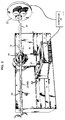
- FIG. 3 Apparatus for moving the body in relation to the heat source is illustrated in FIG. 3 wherein an elongated body 20, such as an optical fiber preform, is shown mounted on a controllable speed lathe 21.
- the lateral surface of body 20 is exposed to the plasma fireball 12 of a plasma torch 10.
- the plasma torch 10 is mounted on a three-axis positioning stage 30 based on the same bed (not shown) as lathe 21 lathe so that the torch position can be precisely controlled during operation.
- a computer 40 is provided to coordinate and control the rotation of body 20 via lathe 21 and the movement of the torch 10 via positioning stage 30. As will be described, the computer controls the rotational speed of the body 20 about the Z-axis and the speed of torch 10 along the Z-axis in such a fashion that the relative speed of the torch over the body is slower over regions with greater amounts of material to be removed.
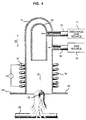
- torch 10 comprises a fused silica mantle 11 connected to a gas source 17 by tube 15 and to a second gas source 18 by tube 16.
- Gas source 17 delivers gas used for the plasma discharge, such as O2, into mantle 11 and through shield 22.
- the plasma fireball 12 is excited by RF power applied by RF generator 14 to RF coil 19.
- Gas source 18 supplies a high ionization threshold gas, such as N2,confined to the outer region of the torch by shield 22. This additional gas creates an area in the upper portion of the confinement region where high RF energy is needed to form a plasma. Since the plasma tends to form in regions where resistance to formation is lowest, the presence of the high threshold gas moves a portion of the fireball outside the torch where it can contact optical fiber preform 20.
- a high ionization threshold gas such as N2
- This additional gas creates an area in the upper portion of the confinement region where high RF energy is needed to form a plasma. Since the plasma tends to form in regions where resistance to formation is lowest, the presence of the high threshold gas moves a portion of the fireball outside the torch where it can contact optical fiber preform 20.
- lathe 21 is preferably a glass lathe having simultaneously rotating chucks at both ends of body 20, such as a Litton Glass Lathe marketed by Litton Engineering Co.
- the standard chuck rotation motor was replaced by a stepmotor, such as a Model M106-205 stepmotor marketed by Compu Motor Division of Parker Hannifin Corp., Petaluma, Califomia.
- the lathe chuck orientation and instantaneous velocity can be controlled in increments of 1° and varied between zero and 200 rpm.
- Additional stepmotors are provided to drive the three axes of the positioning stage 30 controlling the location and traverse speed of torch 10.
- Operation of the preform rotation and torch traverse stepmotors is accomplished under control of computer 40 which can be an AT&T PC6300 computer equiped with a Compu Motor PC-23 Motor Indexer.
- computer 40 which can be an AT&T PC6300 computer equiped with a Compu Motor PC-23 Motor Indexer.
- the instantaneous rotational velocity of body 20 can be continuously adjusted to match a desired residence time under the torch for a particular angular position and longitudinal distance along body 20.
- the working distance between the torch and the surface of body 20 is preferably fixed for each etch pass.
- the preferred working distance is 5-10 mm.
- the control algorithm is generated as follows. First, the etch rate E for the type of material comprising body 20 is determined empirically for a desired rotation rate, torch working distance and torch traverse velocity. Next, the amount of material to be removed at each incremental location i on the body is determined, and third, a set of desired residence times for etching at each location--termed a residence time profile (t i )-- is calculated and used to control the relative speed between the heat source and the surface of the body.
- etching rate E is valid only for the experimental conditions under which E was determined. For example, depending on the rate of rotation of the body relative to the transverse speed of the torch, some turn-to-turn overlap of the etching region will result from the finite width of the plasma fireball. Thus a given location on the body surface might experience preheating and etching over some multiple of turns due to the overlap, interspersed with cooling periods while the location is out of the fireball. Thus in the absence of complex mathematical modeling of the etch rate, it is preferred to duplicate as nearly as possible, the conditions under which E was determined. This can be accomplished by maintaining the average rotation rate and torch traverse speed equal to those used in the test to determine E.
- the rotation rate varies symmetrically about the test RPM and the average rotation rate equals the test RPM.
- the traverse speed of the torch is preferably fixed during the etch run at the same constant value used in the etch rate determination test.
- the etch zone follows a distorted helical path of constant pitch down body 20.
- the speed is chosen to be sufficiently slow that the swath of each etch zone overlaps at each rotation. It is preferably also slower than the average surface speed due to rotation.
- the pulses needed to drive the lathe and torch stepmotors are generated under the command of the PC-23.
- the rotation stepmotor requires an exact number of pulses to effect exactly one revolution of the body 20 if it is not to lose positional accuracy. Preferably this is accomplished by iteratively adjusting the rate information provided by the calculated residence time profile, so that the integrated total equals the number of pulses required for one full turn, while the motor is gradually ramped up and down to the desired speeds.
- the body 20 is an optical fiber preform
- the body is preferably subjected to constant-heating pass to anneal any thermal stress caused by the etching process.
- the eccentricity of the core of a 23.8 mm diameter optical fiber preform was determined by optical scanning at five positions along the preform and interpolated for positions in between.
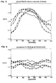
- the measured profile is shown in FIG. 5, which plots the distance d, between core periphery and preform periphery for 20° increments.
- the five plots are for five positions, designated 0 to 4, along the preform length.
- the preform is eccentric with a maximum eccentricity at about 150°.
- the measured eccentricity profile (FIG. 5), was used to calculate the residence profile for the controllable speed lathe in accordance with the algorithm described above.
- the preform was mounted on the lathe so that the orientation of the eccentricity with respect to the torch was known.
- the RF plasma torch set to operate at 28 KW plate power was turned on, and the preform was rotated using the calculated residence profile while the torch was moved along the length of the preform at a constant rate of 5 cm per min. After etching, the preform was annealed and remeasured.
- FIG. 6 shows the eccentricity profile at five locations designated 0 to 4 along the preform after the single etch pass. As can be observed the degree of eccentricity is markedky reduced.
Landscapes
- Chemical & Material Sciences (AREA)
- Engineering & Computer Science (AREA)
- Organic Chemistry (AREA)
- Materials Engineering (AREA)
- Life Sciences & Earth Sciences (AREA)
- General Life Sciences & Earth Sciences (AREA)
- Geochemistry & Mineralogy (AREA)
- Manufacturing & Machinery (AREA)
- General Chemical & Material Sciences (AREA)
- Chemical Kinetics & Catalysis (AREA)
- Physics & Mathematics (AREA)
- Thermal Sciences (AREA)
- Manufacture, Treatment Of Glass Fibers (AREA)
Claims (8)
- Verfahren zur Änderung des Querschnittes eines Materialkörpers, das folgende Schritte umfaßt:a) man bestimmt für jeden von mehreren Bereichen auf der seitlichen Oberfläche des Körpers, in welchem Ausmaß der Körper in diesen Bereichen überschüssiges Material gegenüber einer gewünschten Form aufweist, mißt dabei die Radialabmessungen des Körpers an mehreren verschiedenen Stellen und ermittelt die Radialabmessung des Körpers an nicht gemessenen Stellen durch Interpolation;b) man setzt den Körper einer lokalen Wärmequelle aus, die eine ausreichend hohe Temperatur besitzt, um Material von der Oberfläche des Körpers zu entfernen; undc) man bewegt die Körperoberfläche im Verhältnis zu der Quelle mit einer Geschwindigkeit, die in Bereichen abnimmt, in denen der Körper überschüssiges Material gegenüber einer gewünschten Form aufweist, um so in diesen Überschußbereichen mehr Material als in anderen Bereichen des Körpers zu entfernen.
- Verfahren zur Änderung des Querschnittes eines Materialkörpers, das folgende Schritte aufweist:a) man bestimmt für jeden von mehreren Bereichen auf der seitlichen Oberfläche des Körpers, in welchem Ausmaß der Körper in diesen Bereichen überschüssiges Material gegenüber einer gewünschten Form aufweist;b) man setzt den Körper einem Plasmabrenner zur Erzeugung einer Plasmafeuerkugel aus, die eine ausreichend hohe Temperatur besitzt, um Material von der Oberfläche des Körpers zu entfernen; undc) man bewegt die Körperoberfläche im Verhältnis zu dem Plasmabrenner mit einer Geschwindigkeit, die in Bereichen abnimmt, in denen der Körper überschüssiges Material gegenüber einer gewünschten Form aufweist, um so in diesen Überschußbereichen mehr Material als in anderen Bereichen des Körpers zu entfernen.
- Verfahren nach Anspruch 1 oder 2, bei dem man den Körper im Verhältnis zu der Quelle oder dem Plasmabrenner durch Drehung des Körpers um eine in Längsrichtung verlaufende Achse bewegt und gleichzeitig die Quelle oder den Plasmabrenner parallel zu der Achse verschiebt.
- Verfahren nach Anspruch 3, bei dem man den Körper in einer für jede Umdrehung festgelegten konstanten Zeitspanne mit variabler Drehgeschwindigkeit um die Achse dreht.
- Verfahren nach Anspruch 3, bei dem man die Quelle oder den Brenner mit konstanter Geschwindigkeit parallel zu der Achse verschiebt.
- Verfahren nach Anspruch 1 oder 2, bei dem der Körper feuerfestes Material enthält.
- Verfahren nach Anspruch 1 oder 2, bei dem der Körper einen Lichtleitfaserrohling enthält.
- Vorrichtung zur Veränderung des Querschnittes eines Körpers (20 nach FIG. 3), die folgende Teile aufweist: (a) Drehbankmittel (21), um den Körper mit regelbarer Drehgeschwindigkeit um eine in Längsrichtung verlaufende Achse zu drehen; (b) eine lokale Wärmequelle zur Erzeugung ausreichender Wärme, um Material von dem Körper zu entfernen; (c) Verschiebungsmittel (30), um die lokale Wärmequelle in der Nähe des Körpers parallel zu der Achse zu bewegen; dabei weist
die lokale Wärmequelle einen Plasmabrenner (10) zur Erzeugung einer Plasmafeuerkugel (12) und die Vorrichtung Regelungsmittel (40) zur Regelung der Drehgeschwindigkeit des Drehbankmittels auf, so daß die Geschwindigkeit der Körperoberfläche im Verhältnis zu dem Brenner in Bereichen abnimmt, in denen der Körper überschüssiges Material gegenüber einer gewünschten Form aufweist.
Applications Claiming Priority (2)
| Application Number | Priority Date | Filing Date | Title |
|---|---|---|---|
| US607020 | 1990-10-31 | ||
| US07/607,020 US5221306A (en) | 1989-12-29 | 1990-10-31 | Method and apparatus for modifying the transverse cross section of a body |
Publications (2)
| Publication Number | Publication Date |
|---|---|
| EP0484035A1 EP0484035A1 (de) | 1992-05-06 |
| EP0484035B1 true EP0484035B1 (de) | 1996-02-28 |
Family
ID=24430460
Family Applications (1)
| Application Number | Title | Priority Date | Filing Date |
|---|---|---|---|
| EP91309752A Expired - Lifetime EP0484035B1 (de) | 1990-10-31 | 1991-10-22 | Verfahren und Vorrichtung zur Änderung des Querschnittes eines Körpers |
Country Status (4)
| Country | Link |
|---|---|
| US (1) | US5221306A (de) |
| EP (1) | EP0484035B1 (de) |
| JP (1) | JP2648409B2 (de) |
| DE (1) | DE69117434T2 (de) |
Families Citing this family (28)
| Publication number | Priority date | Publication date | Assignee | Title |
|---|---|---|---|---|
| US5320660A (en) * | 1991-09-03 | 1994-06-14 | U.S. Philips Corporation | Method of manufacturing an optical fibre |
| USD344963S (en) | 1992-09-02 | 1994-03-08 | Lawhorn Jeffrey W | Laser lathe |
| EP0656325B1 (de) * | 1993-11-29 | 1999-09-22 | AT&T Corp. | Verfahren zum Herstellen von Vorformen für optische Fasern |
| US5558692A (en) * | 1994-07-25 | 1996-09-24 | Corning Incorporated | Optical waveguide preform measurement during manufacture |
| FR2725712B1 (fr) * | 1994-10-18 | 1996-12-13 | Alcatel Fibres Optiques | Procede d'amelioration geometrique d'un tube pour realisation de preforme |
| FR2728888B1 (fr) * | 1994-12-29 | 1997-01-31 | Alcatel Cable | Procede d'obtention de preforme de fibre optique employant la recharge plasma |
| US5672192A (en) * | 1996-05-30 | 1997-09-30 | Lucent Technologies Inc. | Method of making optical fiber using a plasma torch fiber-drawing furnace |
| DE19629169C1 (de) * | 1996-07-19 | 1997-12-11 | Heraeus Quarzglas | Verfahren und Vorrichtung zur Herstellung eines zylinderförmigen Bauteils aus Glas |
| US5868815A (en) * | 1997-02-20 | 1999-02-09 | Lucent Technologies Inc. | Method of making an optical fiber by blowing on a preform tube to enhance collapse |
| JP4159247B2 (ja) | 1997-08-19 | 2008-10-01 | ピレリー・カビ・エ・システミ・ソチエタ・ペル・アツィオーニ | 光ファイバの予成形体の製造方法及びその装置 |
| US5979190A (en) * | 1997-09-29 | 1999-11-09 | Lucent Technologies Inc. | Method for manufacturing an article comprising a refractory a dielectric body |
| US5861047A (en) * | 1997-09-29 | 1999-01-19 | Lucent Technologies Inc. | Method for manufacturing an article comprising a refractory dielectric body |
| FR2777273B1 (fr) * | 1998-04-09 | 2000-05-12 | Alsthom Cge Alcatel | Soudage bout a bout de preformes de fibres optiques a l'aide d'une torche a plasma |
| JP2000047039A (ja) * | 1998-07-29 | 2000-02-18 | Shin Etsu Chem Co Ltd | 光ファイバ母材インゴット、及びその製造方法 |
| US6041623A (en) * | 1998-08-27 | 2000-03-28 | Lucent Technologies Inc. | Process for fabricating article comprising refractory dielectric body |
| US6314765B1 (en) * | 1998-10-06 | 2001-11-13 | Alcatel | Method and apparatus for controlling the shape and position of a deformable object |
| DE60019029T2 (de) | 1999-07-02 | 2006-02-16 | Shin-Etsu Chemical Co., Ltd. | Verfahren und Vorrichtung zum herstellen einer Vorform aus Glas für optische Fasern mittels des Aussenabscheidungsverfahrens |
| US6481721B1 (en) | 1999-07-15 | 2002-11-19 | Lucent Technologies Inc. | Method and apparatus for overcladding a glass rod |
| US7574875B2 (en) * | 1999-09-29 | 2009-08-18 | Fibre Ottiche Sud - F.O.S. S.P.A. | Method for vapour deposition on an elongated substrate |
| EP1894898B1 (de) * | 1999-12-01 | 2013-02-13 | Shin-Etsu Chemical Co., Ltd. | Verfahren zur Änderung eines Basismaterials für Lichtwellenleiter |
| US6532773B1 (en) | 2000-06-30 | 2003-03-18 | Fitel Usa Corp. | Method of modifying the index profile of an optical fiber preform in the longitudinal direction |
| US6732549B1 (en) * | 2000-08-01 | 2004-05-11 | Lucent Technologies Inc. | Multi-pass sintering of a sol-gel body through a hot zone |
| JP2002154838A (ja) * | 2000-11-16 | 2002-05-28 | Shin Etsu Chem Co Ltd | 光ファイバ用ガラス母材の製造方法 |
| US6769275B2 (en) * | 2002-03-15 | 2004-08-03 | Fibercore, Inc. | Method for making optical fiber preform using simultaneous inside and outside deposition |
| DE50204852D1 (de) * | 2002-03-28 | 2005-12-15 | Plasma Treat Gmbh | Verfahren und Vorrichtung zum Schliessen von Glasampullen |
| US20040221617A1 (en) * | 2003-05-05 | 2004-11-11 | Fleming James William | Methods for modifying ovality of optical fiber preforms |
| JP2005060148A (ja) * | 2003-08-08 | 2005-03-10 | Sumitomo Electric Ind Ltd | 光ファイバ用母材の製造方法及び光ファイバ用母材並びに光ファイバの製造方法及び光ファイバ |
| WO2008046447A1 (en) * | 2006-10-17 | 2008-04-24 | Prysmian S.P.A. | Process for manufacturing a low-attenuation optical fiber |
Family Cites Families (16)
| Publication number | Priority date | Publication date | Assignee | Title |
|---|---|---|---|---|
| US3492467A (en) * | 1967-04-07 | 1970-01-27 | Westinghouse Electric Corp | Tool offset control for digital numerically controlled point-to-point machine tools |
| US3698268A (en) * | 1970-08-07 | 1972-10-17 | Bendix Corp | Numerical control system for interrupted cutting conditions |
| US3671839A (en) * | 1970-09-23 | 1972-06-20 | Siemens Ag | Method and apparatus for automatic programmed control of a machine tool |
| US3684474A (en) * | 1970-11-12 | 1972-08-15 | Dow Chemical Co | Conveying and forming methods and apparatus for fibers having bulbous ends |
| DE2824624C3 (de) * | 1978-06-05 | 1981-10-15 | Goetze Ag, 5093 Burscheid | Drehmaschine zum Bearbeiten der Umfangsflächen von unrunden Werkstücken |
| NL7812246A (nl) * | 1978-12-18 | 1980-06-20 | Philips Nv | Werkwijze en inrichting voor het verspanend bewerken van glas en glasachtige materialen alsmede werkstuk van glas of glasachtig materiaal bewerkt volgens de werkwijze. |
| JPS601956A (ja) * | 1983-06-17 | 1985-01-08 | Sony Corp | デイジタルデ−タの変調方法 |
| US4498917A (en) * | 1983-07-26 | 1985-02-12 | Olin Corporation | Method and apparatus for laser sizing of optical fibers |
| US4491463A (en) * | 1983-07-26 | 1985-01-01 | Olin Corporation | Laser sizing method and apparatus for fiber optic buffers |
| JPS6195770A (ja) * | 1984-10-17 | 1986-05-14 | Sumitomo Electric Ind Ltd | セラミツク焼結体の加工法 |
| FR2589461B1 (fr) * | 1985-10-31 | 1992-07-24 | Fibres Optiques Ind | Procede de fabrication d'elements etires a base de silice et elements obtenus |
| JPS62226831A (ja) * | 1986-03-27 | 1987-10-05 | Mitsubishi Cable Ind Ltd | 光フアイバ母材の自動外径調整方法 |
| US4759243A (en) * | 1986-12-19 | 1988-07-26 | General Electric Company | Method and apparatus for optimizing single point machining operations |
| JPH03187944A (ja) * | 1989-12-15 | 1991-08-15 | Sumitomo Electric Ind Ltd | ガラス体の加熱処理方法 |
| US5000771A (en) * | 1989-12-29 | 1991-03-19 | At&T Bell Laboratories | Method for manufacturing an article comprising a refractory dielectric body |
| FR2657864B1 (fr) * | 1990-02-02 | 1992-04-10 | Alsthom Cge Alcatel | Procede de fabrication de preformes pour fibres optiques de caracteristiques regulieres. |
-
1990
- 1990-10-31 US US07/607,020 patent/US5221306A/en not_active Expired - Lifetime
-
1991
- 1991-09-27 JP JP3274908A patent/JP2648409B2/ja not_active Expired - Lifetime
- 1991-10-22 EP EP91309752A patent/EP0484035B1/de not_active Expired - Lifetime
- 1991-10-22 DE DE69117434T patent/DE69117434T2/de not_active Expired - Lifetime
Also Published As
| Publication number | Publication date |
|---|---|
| DE69117434D1 (de) | 1996-04-04 |
| US5221306A (en) | 1993-06-22 |
| EP0484035A1 (de) | 1992-05-06 |
| JPH04349134A (ja) | 1992-12-03 |
| JP2648409B2 (ja) | 1997-08-27 |
| DE69117434T2 (de) | 1996-10-24 |
Similar Documents
| Publication | Publication Date | Title |
|---|---|---|
| EP0484035B1 (de) | Verfahren und Vorrichtung zur Änderung des Querschnittes eines Körpers | |
| EP0845441B1 (de) | Verfahren und Vorrichtung zum Herstellen einer Vorform für optische Fasern | |
| US4596589A (en) | Method for producing a single mode fiber preform | |
| EP0138512B1 (de) | Verfahren zur Herstellung einer beschichteten Einfachpolarisationsfaser | |
| US9720264B2 (en) | Polarization-maintaining optical fibre and preform and method for producing the same | |
| US6091500A (en) | Method and apparatus for measuring overclad tubes | |
| KR20010081941A (ko) | 광섬유 프리폼의 제작 방법 | |
| US7062941B2 (en) | Manufacturing method of optical fiber preform | |
| US6532773B1 (en) | Method of modifying the index profile of an optical fiber preform in the longitudinal direction | |
| CA1129727A (en) | Method of fabricating large optical preforms | |
| JP3188403B2 (ja) | 光ファイバ母材の延伸方法および延伸装置 | |
| GB2118165A (en) | Improved manufacture of optical fibers | |
| US7734135B2 (en) | Method and device for manufacturing optical preforms, as well as the optical fibres obtained therewith | |
| EP4105185B1 (de) | Verfahren zum herstellen einer vorform für eine optische mehrkernfaser sowie einer mehrkernfaser. | |
| EP1110919B1 (de) | Verfahren zum Herstellen einer Vorform für optische Fasern mittels chemischer Abscheidung aus der Dampfphase | |
| EP0089560B1 (de) | Verfahren zum Herstellen von Vorformen für optische Fasern | |
| WO2000027767A1 (en) | Quartz glass tube for use in the production of optical fiber preforms | |
| US9475729B2 (en) | Method for the unidirectional and or bidirectional removal of a cladding layer of an optical preform | |
| JP3151386B2 (ja) | 光ファイバ母材の製造方法 | |
| JP4056778B2 (ja) | 光ファイバ母材の製造方法 | |
| WO2003004426A1 (fr) | Procede de fabrication d'une preforme de fibre optique | |
| CN117865454A (zh) | 纤芯数值孔径可调一体化特种光纤的制备方法及特种光纤 | |
| JPS5899129A (ja) | ロツドレンズの製造方法 | |
| WO2000009455A1 (en) | Method making a fiber preform using cooled spindle | |
| JPS6256092B2 (de) |
Legal Events
| Date | Code | Title | Description |
|---|---|---|---|
| PUAI | Public reference made under article 153(3) epc to a published international application that has entered the european phase |
Free format text: ORIGINAL CODE: 0009012 |
|
| AK | Designated contracting states |
Kind code of ref document: A1 Designated state(s): DE FR GB IT |
|
| 17P | Request for examination filed |
Effective date: 19921023 |
|
| 17Q | First examination report despatched |
Effective date: 19940303 |
|
| RAP3 | Party data changed (applicant data changed or rights of an application transferred) |
Owner name: AT&T CORP. |
|
| GRAA | (expected) grant |
Free format text: ORIGINAL CODE: 0009210 |
|
| AK | Designated contracting states |
Kind code of ref document: B1 Designated state(s): DE FR GB IT |
|
| ITF | It: translation for a ep patent filed | ||
| ET | Fr: translation filed | ||
| REF | Corresponds to: |
Ref document number: 69117434 Country of ref document: DE Date of ref document: 19960404 |
|
| PLBE | No opposition filed within time limit |
Free format text: ORIGINAL CODE: 0009261 |
|
| STAA | Information on the status of an ep patent application or granted ep patent |
Free format text: STATUS: NO OPPOSITION FILED WITHIN TIME LIMIT |
|
| 26N | No opposition filed | ||
| REG | Reference to a national code |
Ref country code: GB Ref legal event code: IF02 |
|
| PG25 | Lapsed in a contracting state [announced via postgrant information from national office to epo] |
Ref country code: IT Free format text: LAPSE BECAUSE OF NON-PAYMENT OF DUE FEES;WARNING: LAPSES OF ITALIAN PATENTS WITH EFFECTIVE DATE BEFORE 2007 MAY HAVE OCCURRED AT ANY TIME BEFORE 2007. THE CORRECT EFFECTIVE DATE MAY BE DIFFERENT FROM THE ONE RECORDED. Effective date: 20051022 |
|
| PGFP | Annual fee paid to national office [announced via postgrant information from national office to epo] |
Ref country code: DE Payment date: 20091028 Year of fee payment: 19 |
|
| PGFP | Annual fee paid to national office [announced via postgrant information from national office to epo] |
Ref country code: FR Payment date: 20091029 Year of fee payment: 19 Ref country code: GB Payment date: 20091026 Year of fee payment: 19 |
|
| GBPC | Gb: european patent ceased through non-payment of renewal fee |
Effective date: 20101022 |
|
| PG25 | Lapsed in a contracting state [announced via postgrant information from national office to epo] |
Ref country code: FR Free format text: LAPSE BECAUSE OF NON-PAYMENT OF DUE FEES Effective date: 20101102 |
|
| REG | Reference to a national code |
Ref country code: FR Ref legal event code: ST Effective date: 20110630 |
|
| PG25 | Lapsed in a contracting state [announced via postgrant information from national office to epo] |
Ref country code: GB Free format text: LAPSE BECAUSE OF NON-PAYMENT OF DUE FEES Effective date: 20101022 |
|
| REG | Reference to a national code |
Ref country code: DE Ref legal event code: R119 Ref document number: 69117434 Country of ref document: DE Effective date: 20110502 |
|
| PG25 | Lapsed in a contracting state [announced via postgrant information from national office to epo] |
Ref country code: DE Free format text: LAPSE BECAUSE OF NON-PAYMENT OF DUE FEES Effective date: 20110502 |