EP0484535A1 - Dispositif de fermeture de portes - Google Patents
Dispositif de fermeture de portes Download PDFInfo
- Publication number
- EP0484535A1 EP0484535A1 EP91904320A EP91904320A EP0484535A1 EP 0484535 A1 EP0484535 A1 EP 0484535A1 EP 91904320 A EP91904320 A EP 91904320A EP 91904320 A EP91904320 A EP 91904320A EP 0484535 A1 EP0484535 A1 EP 0484535A1
- Authority
- EP
- European Patent Office
- Prior art keywords
- door
- closer
- arm
- damper
- adjusting arm
- Prior art date
- Legal status (The legal status is an assumption and is not a legal conclusion. Google has not performed a legal analysis and makes no representation as to the accuracy of the status listed.)
- Granted
Links
- 230000008878 coupling Effects 0.000 claims description 11
- 238000010168 coupling process Methods 0.000 claims description 11
- 238000005859 coupling reaction Methods 0.000 claims description 11
- 230000007246 mechanism Effects 0.000 claims description 9
- 238000012423 maintenance Methods 0.000 abstract description 4
- 230000003247 decreasing effect Effects 0.000 abstract description 3
- 238000013016 damping Methods 0.000 abstract 3
- 239000002184 metal Substances 0.000 abstract 2
- 230000001747 exhibiting effect Effects 0.000 abstract 1
- 239000011521 glass Substances 0.000 description 4
- 239000012530 fluid Substances 0.000 description 3
- 238000007689 inspection Methods 0.000 description 3
- 230000008439 repair process Effects 0.000 description 3
- 230000000694 effects Effects 0.000 description 2
- 230000004075 alteration Effects 0.000 description 1
- 230000002950 deficient Effects 0.000 description 1
- 230000001105 regulatory effect Effects 0.000 description 1
Images


Classifications
-
- E—FIXED CONSTRUCTIONS
- E05—LOCKS; KEYS; WINDOW OR DOOR FITTINGS; SAFES
- E05F—DEVICES FOR MOVING WINGS INTO OPEN OR CLOSED POSITION; CHECKS FOR WINGS; WING FITTINGS NOT OTHERWISE PROVIDED FOR, CONCERNED WITH THE FUNCTIONING OF THE WING
- E05F3/00—Closers or openers with braking devices, e.g. checks; Construction of pneumatic or liquid braking devices
- E05F3/14—Closers or openers with braking devices, e.g. checks; Construction of pneumatic or liquid braking devices with fluid brakes of the rotary type
-
- E—FIXED CONSTRUCTIONS
- E05—LOCKS; KEYS; WINDOW OR DOOR FITTINGS; SAFES
- E05F—DEVICES FOR MOVING WINGS INTO OPEN OR CLOSED POSITION; CHECKS FOR WINGS; WING FITTINGS NOT OTHERWISE PROVIDED FOR, CONCERNED WITH THE FUNCTIONING OF THE WING
- E05F3/00—Closers or openers with braking devices, e.g. checks; Construction of pneumatic or liquid braking devices
- E05F3/22—Additional arrangements for closers, e.g. for holding the wing in opened or other position
-
- E—FIXED CONSTRUCTIONS
- E05—LOCKS; KEYS; WINDOW OR DOOR FITTINGS; SAFES
- E05F—DEVICES FOR MOVING WINGS INTO OPEN OR CLOSED POSITION; CHECKS FOR WINGS; WING FITTINGS NOT OTHERWISE PROVIDED FOR, CONCERNED WITH THE FUNCTIONING OF THE WING
- E05F3/00—Closers or openers with braking devices, e.g. checks; Construction of pneumatic or liquid braking devices
-
- E—FIXED CONSTRUCTIONS
- E05—LOCKS; KEYS; WINDOW OR DOOR FITTINGS; SAFES
- E05Y—INDEXING SCHEME ASSOCIATED WITH SUBCLASSES E05D AND E05F, RELATING TO CONSTRUCTION ELEMENTS, ELECTRIC CONTROL, POWER SUPPLY, POWER SIGNAL OR TRANSMISSION, USER INTERFACES, MOUNTING OR COUPLING, DETAILS, ACCESSORIES, AUXILIARY OPERATIONS NOT OTHERWISE PROVIDED FOR, APPLICATION THEREOF
- E05Y2900/00—Application of doors, windows, wings or fittings thereof
- E05Y2900/10—Application of doors, windows, wings or fittings thereof for buildings or parts thereof
- E05Y2900/13—Type of wing
- E05Y2900/132—Doors
Definitions
- This invention relates to a door closer in which a recovering force is accumulated in a door closing direction at the time of opening a door and a braking force of a damper is performed at the time of closing the door and, more particularly, to a device for automatically closing a door by mounting a closer body having a function of a damper at the door and an upper frame through arms.
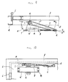
- a conventional door closer consists, as shown in Figs. 9 and 10 showing the using state of a door closer, of a closer body a, an arm c fixed at one end thereof to a piston driving shaft b of the door closer body a, and an adjusting arm g pivotally secured at one end thereof to the end of the arm c via a screw d, etc., and pivotally secured at the other end thereof to a mounting plate e via a screw f, etc.,
- the door closer body a has a hydraulic cylinder (not shown) in a body case a', and a piston (not shown) telescopically inserted into the hydraulic cylinder through a return spring.
- the closer body a is clamped at the upper portion of a door j openably pivotally secured via a hinge i at the hanging side to a vertical frame h through one or more clamping screws k, and the mounting plate e is clamped at an upper frame l via one or more clamping screws (not shown).
- the piston is telescopically driven against the return spring by the piston driving shaft b rotated by both the arms by the door opening operation, the recovering force is accumulated at the return spring, and the door j is so mounted as to be automatically closed by the accumulated recovering force accumulated at the return spring.
- the closer body a and the mounting plate e are respectively mounted at the door j and the upper frame l in a door closing state.
- the door closer is so mounted that a recovering force of certain degree is accumulated at the return spring even at the time of closing the door by considering a latching in the door closing state.
- the piston driving shaft b in order to fully open the door in a direction of an arrow m from the door closing state in Fig. 9, the piston driving shaft b must be rotated at a considerably large rotating angle by the arm c. Accordingly, the internal structure of the door closer body a must be so composed as to be allowed to be rotatable at the large angle. This considerably restricts the degree of freedoms of the door closer body a in design.
- the conventional door closer further has the following disadvantage.
- a closer body a and a mounting plate e are fixed directly to a door j and an upper frame l in a state that all components are assembled completely.
- arms c an g are rotatably energized in a direction of an arrow m in Fig. 9 by the recovering force accumulated at a return spring, the mounting positioning and the mounting works of the closer body a and the mounting plate e are not so easy, but long time and labor are wasted.
- a primary object of the present invention is to provide a door closer which can eliminate the problems of the conventional door closer and can obviate a concept of mounting a closer body at a door to eliminate necessity of mounting a large closer body at the door by disposing a closer body as a damper at the pivotally securing position of an arm and an adjusting arm, thereby deleting impossibility of mounting the door closer even at a glass engaging door.
- Another object of the present invention is to provide a door closer which can improve the degree of freedoms of a closer body in design thereof by reducing a large rotating angle of a damper driving shaft of the closer body to a relatively small value to open a door from a door closing state to a door fully opening state.
- Still another object of the present invention is to provide a door closer which can gradually reduce an arm crossing angle between an arm and an adjusting arm immediately before a door fully opening state by establishing the arranging position of a closer body as described above thereby to decrease a recovering force of a return spring in a door closing direction, thereby holding the door in the door fully opening state even without stopper mechanism.
- the arm and the adjusting arm of the door closer are disposed at the upper and lower surfaces thereof in the same plane.
- a stepwise difference between the upper surfaces of the arm and the adjusting arm is equal to the stepwise difference between the lower surfaces of the arm and the adjusting arm of the door closer.
- one type of door closer may be used in both a right-hand side openable door and a left-hand side openable door.
- a speed adjusting screw of the door is exposed on both the upper surface and the lower surface of the closer body of the door closer.
- the speed of the door closer of both the right-hand side openable type and the left-hand side openable type can be regulated by using a screwdriver from below.
- a pivotally securing position of an adjusting arm as a joint is provided with respect to the door closer, and the door closer can thus be extremely easily and rapidly fixed at a predetermined position to the door and the upper frame. Further, while door mounting fittings and an upper frame mounting plate remain removably attached to the door and the upper frame, only the closer body and both the arm and the adjusting arm can be easily detached, thereby facilitating an inspection, a maintenance and a repair, etc., of the closer body.
- a door closer having a return spring for accumulating a recovering force in a door closing direction at the time of opening a door for performing a braking force by a damper at the time of closing the door
- a closer body internally containing a mechanism for performing an operation as said damper in a body case
- an adjusting arm coupled perpendicularly to a driving shaft for the damper of said closer body to be projected laterally rotatably
- a coupling bracket for pivotally securing an upper frame mounting plate directly or indirectly to the end of said adjusting arm via step screws to be horizontally rotatable
- a door mounting arm projected laterally from said closer body for pivotally securing a door mounting bracket to the end of said arm via a step screw to be horizontally rotatable.
- a door closer having a return spring for accumulating a recovering force in a door closing direction at the time of opening a door for performing a braking force by a damper at the time of closing the door
- a closer body internally containing a mechanism for performing an operation as said damper in a body case
- an adjusting arm coupled perpendicularly to a driving shaft for the damper of said closer body to be projected laterally rotatably
- a coupling bracket for pivotally securing an upper frame mounting plate directly or indirectly to the end of said adjusting arm via step screws to be horizontally rotatable
- a door mounting arm projected laterally from said closer body for pivotally securing a door mounting bracket to the end of said arm via a step screw to be horizontally rotatable
- a door closer having a return spring for accumulating a recovering force in a door closing direction at the time of opening a door for performing a braking force by a damper at the time of closing the door
- a closer body internally containing a mechanism for performing an operation as said damper in a body case
- an adjusting arm coupled perpendicularly to a driving shaft for the damper of said closer body to be projected laterally rotatably, said adjusting arm is pivotally secured at a base end thereof to be vertically rotatable longitudinally of said driving shaft, an upper frame mounting plate pivotally secured to a coupling bracket vertically rotatably provided at the end of said adjusting arm via a step screw to be horizontally rotatable and removable, and a door mounting arm projected laterally from said closer body for pivotally securing a door mounting bracket to the end of said arm via a step screw to be horizontally rotatable.
- the door mounting bracket is clamped at the upper portion of the door at the handing side to be pivotally secured to the vertical frame to be openably via the hinges.
- the upper frame mounting plate is mounted at the position corresponding to the door mounting bracket on the rear surface of the upper frame via the screw.
- the end of the arm fixed to the body case is pivotally secured to the door mounting bracket via the step screw to be horizontally rotatable.
- the adjusting arm rotatably coupled perpendicularly to the driving shaft is pivotally secured at the end thereof to the upper frame mounting plate via a step screw to be horizontally rotatable, thereby completing the mounting of the closer body.
- the adjusting arm When the door mounted by the door closer is opened by rotation, the adjusting arm is rotated in the same direction as the door opening direction, while the arm fixed to the body case is rotated reversely. As a result, the driving shaft of the damper of the closer body is rotated in a predetermined direction, and driven against the return spring, thereby accumulating a recovering force at the return spring.
- the door mounting bracket can be sufficiently reduced in size in case of the above-described mounting work, even if the door closer mounting portion of the door is narrow, the door closer can be easily mounted.
- the closer body is arranged at the pivotally securing position of the arm and the adjusting arm in case of opening and closing the door, it is not necessary to rotate the driving shaft of the closer body over a considerably large rotating angle.
- the degree of freedoms in design of the closer body is increased, and the door closer can be reduced in size, and manufactured in a light weight.
- the upper and lower surfaces of the arm and the adjusting arm are formed in the same plane, or the stepwise differences of the upper and lower surfaces of the arm and the adjusting arm are equal to each other. Therefore, when the door closer used in the right-hand side door opening type is used to the left-hand side door opening type, the door closer is inverted upside down, and the door mounting bracket pivotally secured to the arm and the adjusting arm and the upper frame mounting plate is attached to the upper surface of the inverted door closer, thereby mounting the door closer on the door and the upper frame without trouble.
- the speed adjusting screw at the time of closing the door can be adjusted by a screwdriver from below even after the door closer is inverted upside down.
- the adjusting arm is vertically rotatable longitudinally of the driving shaft at the base end side thereof, and the upper frame mounting plate is provided at the end of the adjusting arm through the coupling bracket vertically rotatable. Therefore, the closer body can be integrally removed with both the arm and the adjusting arm by releasing the pivotal securing of the coupling bracket at the end of the adjusting arm, the upper frame mounting plate and the arm of the body case, the door mounting bracket in the door closing state.
- a closer body 1 is filled with high viscosity fluid between a rotor (not shown) disposed therein and a stator (not shown) known per se, and liquidtightly sealed with a cover plate, and a driving shaft for a damper (not shown) projecting upward from a central axial hole (not shown) of the cover plate is fixed with a cylindrical cover 3 via a clamping screw 4.
- the closer body 1 has, as shown in Fig. 4, a speed adjusting screw 5 and a door opening angle adjusting screw 6, etc., known per se.
- a speed adjusting screw 5 When the rotor (not shown) is rotated by a driving shaft, and damper effect is performed by the resistance force of the high viscosity fluid between the rotor and the stator.
- any members may be employed if the damper effect is performed.
- An arm 7 substantially perpendicular to the axial center of the body case 2 of the closer body 1 is projected laterally from the body case 2, and a door mounting bracket 8 of substantially planely T shape is so detachably pivotally secured to the end of the arm 7 via a step screw 9 engaged into the threaded hole 8a of the bracket 8 as to be inserted into the through hole 7a of the arm 7 to be horizontally rotatable.
- An adjusting screw 10 is laterally projected from the cover 3, and so pivotally secured at a shaft pin 11 as to be vertically upwardly or downwardly rotatable as indicated by arrows O and O' in Fig. 1.
- the adjusting arm 10 is formed of an arm body 10a pivotally secured at a base end thereof to the cover 3, a threaded lever 10b rotatably around an axis thereof and slidable in a longitudinal direction to be inserted into a long hole (not shown) formed longitudinally of the arm body 10a, and adjusting threads 10c rotatably supported at a home position thereof to the arm body 10a and formed threadedly on the threaded lever 10b.
- the threaded lever 10b is longitudinally slid with respect to the arm body 10a, and the adjusting arm 10 is so constructed that the entire length of the adjusting arm 10 is telescopically adjusted to be elongated or contracted.
- a coupling bracket 12 is so pivotally secured to the end of the adjusting arm 10, i.e., the end of the threaded lever 10b via a shaft pin 13 as to be vertically rotatable as indicated by arrows O and O' in Fig. 1.
- An upper frame mounting plate 14 is so pivotally secured to the end of the adjusting arm 10 as to be inserted into the through hole 12a of the coupling bracket 12 and horizontally rotatable and detachable via a step screw 15 engaged within the threaded hole 14a of the upper frame mounting plate 14.
- the door mounting bracket 8 and the upper frame mounting plate 14 are clamped with clamping screws (not shown) at the upper portion of the door 18 and the lower surface of an upper frame 19 at the hanging side pivotally secured openably via hinges 17,.., to a vertical frame 16, and the door 18 can be so mounted as to be able to be automatically closed.
- the door mounting bracket 8 and the upper frame mounting plate 14 are respectively so secured to the door 18 and the upper frame 19 in a state as to be separated in advance from the arm 7 and the adjusting arm 10 as described above, and the arm 7 and the adjusting arm 10 are thereafter coupled via the step screws 9 and 15, thereby mounting the door closer.
- a closer body 1 is not mounted at a door 18, but evidently arranged at a pivotally securing position of an arm 7 and an adjusting arm 10. Further, the adjusting arm 10 is pivotally secured at an end thereof directly to an upper frame mounting plate 14. Therefore, the coupling bracket 12 and the shaft pin 11 provided in the third aspect of the embodiment are not necessarily provided.
- the return spring can be provided in the closer body 1 known per se, or provided in the adjusting arm 10.
- the rotating angle of the conventional door (18) is large (180°), but since the crossing angle between the arm 7 and the adjusting arm 10 of the door closer according to the present invention is relatively small, it is not necessary to rotate the damper driving shaft of the closer body 1 at considerably large rotating angle.
- the closer body 1 is composed as the damper, as compared with the case that it is required to be rotated up to 180°, the degree of freedoms in design of the door closer according to the present invention can be largely raised.
- Figs. 7 and 8 show in explanatory side views a second aspect of an embodiment of a door closer of the invention for the convenience of description, in which an arm 7 and an adjusting arm 10 are illustrated in a longitudinal section, wherein Fig. 8(a) shows an embodiment different from that in Figs. 1 to 5, in which the upper surface 7a of the arm 7 and the upper surface 10d of the adjusting arm 10 are formed in the same height (in the same plane), and the lower surface 7b of the arm 7 and the lower surface 10e of the adjusting arm 10 are also formed in the same plane.
- a stepwise difference D1 between the upper surface 7a of the arm 7 and the upper surface 10d of the adjusting arm 10 is formed to be substantially equal to a stepwise difference D2 between the lower surface 7b of the arm 7 and the lower surface 10e of the adjusting arm 10.
- a speed adjusting screw 5 at the lower surface of a body case 2 is exposed externally.
- resistance force of viscous fluid as a damper is controlled not only to adjust the door closing speed, but the adjusting end 5a of the speed adjusting screw 5 is exposed on the upper surface of a cover 3.
- the door closer can be used in both a left-hand side door opening type and a right-hand side door opening type.
- the door closer when the door closer is desired to be used in an alternate side door opening type, the door closer may be inverted upside down.
- the door closer when the door closer is inverted upside down, the upper surface 7a and the lower surface 7b of the arm 7 as well as the upper surface 10d and the lower surface 10e of the adjusting arm 10 are merely inverted upside down, but the heights of the surfaces are invariable. Therefore, the door 18 can be mounted at the upper frame 19 without trouble by switching the door mounting bracket 9 of the arm 7 and the upper frame mounting plate 14 of the adjusting arm 10 at the upper surface side after they are inverted, and the door closer can be used as it is. Further, when the adjusting end 5a of the speed adjusting screw 5 is turned by a screwdriver from below, the door closing speed of the door 18 can be simply adjusted even after the door closer is inverted upside down.
- the degree of freedoms in design of the damper of the door closer can be improved by reducing the rotating angle of the driving shaft of the closer body of the door closer.
- the crossing angle between the arm and the adjusting arm can be reduced in the fully opening state of the door as compared with that of the conventional door closer, it is not necessary to provide a special stopper to maintain the door in the fully opening state.
- the dimensional arrangement of the arm and the adjusting arm of the door closer is provided, and the speed adjusting screw is exposed on both the upper and lower surfaces of the closer body. Therefore, the door closer can be used in both the right-hand side door opening type and the left-hand side door opening type. In both cases, the door closing speed of the door can be adjusted from below.
- the door mounting bracket and the upper frame mounting plate are removed from the arm and the adjusting arm, and respectively secured directly to the door and the upper frame, and thereafter clamped with the step screws, thereby mounting the door closer. Therefore, since the arm and the adjusting arm are held, rotated against the recovering force of the return spring, and the door mounting bracket and the upper frame mounting plate can be simply coupled in the state that the recovering force is accumulated at the return spring to close the door and to latch it, the door closer can be easily and rapidly mounted reliably at a predetermined mounting position in a short period of time by an easy operation.
Landscapes
- Closing And Opening Devices For Wings, And Checks For Wings (AREA)
- Freezers Or Refrigerated Showcases (AREA)
Abstract
Applications Claiming Priority (3)
| Application Number | Priority Date | Filing Date | Title |
|---|---|---|---|
| JP133134/90 | 1990-05-23 | ||
| JP13313490 | 1990-05-23 | ||
| PCT/JP1991/000227 WO1991018174A1 (fr) | 1990-05-23 | 1991-02-22 | Dispositif de fermeture de portes |
Publications (3)
| Publication Number | Publication Date |
|---|---|
| EP0484535A1 true EP0484535A1 (fr) | 1992-05-13 |
| EP0484535A4 EP0484535A4 (en) | 1992-10-28 |
| EP0484535B1 EP0484535B1 (fr) | 1995-05-10 |
Family
ID=15097568
Family Applications (1)
| Application Number | Title | Priority Date | Filing Date |
|---|---|---|---|
| EP91904320A Expired - Lifetime EP0484535B1 (fr) | 1990-05-23 | 1991-02-22 | Dispositif de fermeture de portes |
Country Status (9)
| Country | Link |
|---|---|
| US (1) | US5274880A (fr) |
| EP (1) | EP0484535B1 (fr) |
| KR (1) | KR950007729B1 (fr) |
| AU (1) | AU638312B2 (fr) |
| CA (1) | CA2058965C (fr) |
| DE (1) | DE69109620D1 (fr) |
| IE (1) | IE62399B1 (fr) |
| MX (1) | MX174172B (fr) |
| WO (1) | WO1991018174A1 (fr) |
Families Citing this family (3)
| Publication number | Priority date | Publication date | Assignee | Title |
|---|---|---|---|---|
| KR100202260B1 (ko) * | 1997-03-04 | 1999-06-15 | 우생윤 | 자동도어 클로우저 유니트 |
| DE102011056961A1 (de) * | 2011-07-13 | 2013-01-17 | Dorma Gmbh + Co. Kg | Drehflügelbetätiger-Gestängearm |
| CN106379212B (zh) * | 2016-11-03 | 2019-02-01 | 北京汽车股份有限公司 | 车辆、用于车辆的扶手及扶手的控制方法 |
Family Cites Families (13)
| Publication number | Priority date | Publication date | Assignee | Title |
|---|---|---|---|---|
| AT98293B (de) * | 1923-05-03 | 1924-10-25 | Stanitz & Co | Türschließer. |
| US2472508A (en) * | 1946-09-09 | 1949-06-07 | James G Allen | Door check and closer |
| US2479835A (en) * | 1948-11-05 | 1949-08-23 | Albert E Hill | Check and closer for inner and outer closures |
| SE302262B (fr) * | 1967-06-30 | 1968-07-08 | Optimus Ab | |
| US3579709A (en) * | 1969-12-24 | 1971-05-25 | Charles G Pierie | Door return and check mechanism |
| JPS525486Y2 (fr) * | 1971-05-08 | 1977-02-04 | ||
| JPS5039621Y2 (fr) * | 1971-09-14 | 1975-11-13 | ||
| JPS5523245A (en) * | 1978-08-04 | 1980-02-19 | Chiriyuu Kagaku Kogyo Kk | Checking device for door |
| DE3033496C2 (de) * | 1980-09-05 | 1985-07-25 | Casma di V. Marinoni & Figli, Magenta | In Offenstellung verrastbares Türschließergestänge |
| DE3239062A1 (de) * | 1982-10-22 | 1984-04-26 | Dorma-Baubeschlag Gmbh & Co Kg, 5828 Ennepetal | Tuerschliessergestaenge |
| DE3867160D1 (de) * | 1987-07-15 | 1992-02-06 | Scharwaechter Gmbh Co Kg | Tuerfeststeller, insbesondere fuer kraftwagentueren. |
| JPH0681873B2 (ja) * | 1990-05-23 | 1994-10-19 | スガツネ工業株式会社 | ドアクローザー |
| JPH0539621A (ja) * | 1991-08-07 | 1993-02-19 | Yoshikazu Iwamoto | 携帯掘削機 |
-
1991
- 1991-02-22 AU AU72580/91A patent/AU638312B2/en not_active Ceased
- 1991-02-22 KR KR1019920700082A patent/KR950007729B1/ko not_active Expired - Fee Related
- 1991-02-22 WO PCT/JP1991/000227 patent/WO1991018174A1/fr not_active Ceased
- 1991-02-22 DE DE69109620T patent/DE69109620D1/de not_active Expired - Lifetime
- 1991-02-22 CA CA002058965A patent/CA2058965C/fr not_active Expired - Fee Related
- 1991-02-22 EP EP91904320A patent/EP0484535B1/fr not_active Expired - Lifetime
- 1991-02-22 US US07/778,102 patent/US5274880A/en not_active Expired - Fee Related
- 1991-05-22 IE IE174591A patent/IE62399B1/en not_active IP Right Cessation
- 1991-05-22 MX MX025882A patent/MX174172B/es unknown
Also Published As
| Publication number | Publication date |
|---|---|
| EP0484535B1 (fr) | 1995-05-10 |
| IE62399B1 (en) | 1995-01-25 |
| IE911745A1 (en) | 1991-12-04 |
| US5274880A (en) | 1994-01-04 |
| MX174172B (es) | 1994-04-26 |
| EP0484535A4 (en) | 1992-10-28 |
| CA2058965A1 (fr) | 1991-11-24 |
| AU7258091A (en) | 1991-12-10 |
| AU638312B2 (en) | 1993-06-24 |
| DE69109620D1 (de) | 1995-06-14 |
| WO1991018174A1 (fr) | 1991-11-28 |
| KR920703952A (ko) | 1992-12-18 |
| CA2058965C (fr) | 1995-04-04 |
| KR950007729B1 (ko) | 1995-07-14 |
Similar Documents
| Publication | Publication Date | Title |
|---|---|---|
| CA2560394C (fr) | Dispositif amortisseur pour des charnieres de meubles | |
| CA2080181C (fr) | Placard suspendu a porte tournante | |
| US6922872B2 (en) | Automotive door hinge with structurally integrated pivot | |
| CA2423923C (fr) | Charniere de portiere d'automobile a pivot integre au plan structural | |
| AU4238302A (en) | Automatic door hinge with removable component adapted for structural reassembly | |
| CN113195906A (zh) | 家具驱动装置 | |
| AU2002322234A1 (en) | Automotive door hinge with structurally integrated pivot | |
| EP0484535A1 (fr) | Dispositif de fermeture de portes | |
| US7497532B2 (en) | Carcass member with flap | |
| EP1474581B9 (fr) | Articulation pour meuble | |
| JP2620732B2 (ja) | ドアクローザ | |
| CN220133753U (zh) | 一种双轴暗合页 | |
| JPH03271477A (ja) | 扉、窓等の揺動式開き戸用折りたたみ腕支え具 | |
| CA3020835C (fr) | Bras de chargement d'extremite | |
| CN216841102U (zh) | 一种铝框安装铰链 | |
| US20040261320A1 (en) | Casement window operator system | |
| CN219925879U (zh) | 可伸缩阀门开关f扳手 | |
| KR100770425B1 (ko) | 가구 힌지용 댐핑 장치 | |
| EP1533439B1 (fr) | Dispositif de levage servo-assisté | |
| CN217681285U (zh) | 一种具有稳定结构的转动窗框 | |
| BE1032034B1 (nl) | Een poortactuator | |
| GB2031059A (en) | Spring Biassed Link Hinge | |
| CN210052697U (zh) | 一种船用小型断路器的手柄自动装配装置 | |
| JPH10220101A (ja) | 門扉用ドアクローザ | |
| WO1990001097A1 (fr) | Dispositif servant a eliminer les contraintes causees par des actuateurs lineaires sur les charnieres de grilles d'entrees a actionnement automatique |
Legal Events
| Date | Code | Title | Description |
|---|---|---|---|
| PUAI | Public reference made under article 153(3) epc to a published international application that has entered the european phase |
Free format text: ORIGINAL CODE: 0009012 |
|
| AK | Designated contracting states |
Kind code of ref document: A1 Designated state(s): DE ES FR GB IT |
|
| 17P | Request for examination filed |
Effective date: 19920512 |
|
| A4 | Supplementary search report drawn up and despatched |
Effective date: 19920904 |
|
| AK | Designated contracting states |
Kind code of ref document: A4 Designated state(s): DE ES FR GB IT |
|
| 17Q | First examination report despatched |
Effective date: 19921126 |
|
| GRAA | (expected) grant |
Free format text: ORIGINAL CODE: 0009210 |
|
| AK | Designated contracting states |
Kind code of ref document: B1 Designated state(s): DE ES FR GB IT |
|
| PG25 | Lapsed in a contracting state [announced via postgrant information from national office to epo] |
Ref country code: IT Free format text: LAPSE BECAUSE OF FAILURE TO SUBMIT A TRANSLATION OF THE DESCRIPTION OR TO PAY THE FEE WITHIN THE PRE;WARNING: LAPSES OF ITALIAN PATENTS WITH EFFECTIVE DATE BEFORE 2007 MAY HAVE OCCURRED AT ANY TIME BEFORE 2007. THE CORRECT EFFECTIVE DATE MAY BE DIFFERENT FROM THE ONE RECORDED.SCRIBED TIME-LIMIT Effective date: 19950510 Ref country code: FR Effective date: 19950510 Ref country code: ES Free format text: THE PATENT HAS BEEN ANNULLED BY A DECISION OF A NATIONAL AUTHORITY Effective date: 19950510 |
|
| REF | Corresponds to: |
Ref document number: 69109620 Country of ref document: DE Date of ref document: 19950614 |
|
| PG25 | Lapsed in a contracting state [announced via postgrant information from national office to epo] |
Ref country code: DE Effective date: 19950811 |
|
| EN | Fr: translation not filed | ||
| PLBE | No opposition filed within time limit |
Free format text: ORIGINAL CODE: 0009261 |
|
| STAA | Information on the status of an ep patent application or granted ep patent |
Free format text: STATUS: NO OPPOSITION FILED WITHIN TIME LIMIT |
|
| 26N | No opposition filed | ||
| REG | Reference to a national code |
Ref country code: GB Ref legal event code: IF02 |
|
| PGFP | Annual fee paid to national office [announced via postgrant information from national office to epo] |
Ref country code: GB Payment date: 20030219 Year of fee payment: 13 |
|
| PG25 | Lapsed in a contracting state [announced via postgrant information from national office to epo] |
Ref country code: GB Free format text: LAPSE BECAUSE OF NON-PAYMENT OF DUE FEES Effective date: 20040222 |
|
| GBPC | Gb: european patent ceased through non-payment of renewal fee |
Effective date: 20040222 |