EP0484551B1 - Steuersystem für Roboter mit Beschleunigungs- und Verzögerungszeitkonstanten - Google Patents
Steuersystem für Roboter mit Beschleunigungs- und Verzögerungszeitkonstanten Download PDFInfo
- Publication number
- EP0484551B1 EP0484551B1 EP91909370A EP91909370A EP0484551B1 EP 0484551 B1 EP0484551 B1 EP 0484551B1 EP 91909370 A EP91909370 A EP 91909370A EP 91909370 A EP91909370 A EP 91909370A EP 0484551 B1 EP0484551 B1 EP 0484551B1
- Authority
- EP
- European Patent Office
- Prior art keywords
- acceleration
- time constant
- deceleration time
- robot
- torque
- Prior art date
- Legal status (The legal status is an assumption and is not a legal conclusion. Google has not performed a legal analysis and makes no representation as to the accuracy of the status listed.)
- Expired - Lifetime
Links
Images


Classifications
-
- G—PHYSICS
- G05—CONTROLLING; REGULATING
- G05B—CONTROL OR REGULATING SYSTEMS IN GENERAL; FUNCTIONAL ELEMENTS OF SUCH SYSTEMS; MONITORING OR TESTING ARRANGEMENTS FOR SUCH SYSTEMS OR ELEMENTS
- G05B19/00—Program-control systems
- G05B19/02—Program-control systems electric
- G05B19/18—Numerical control [NC], i.e. automatically operating machines, in particular machine tools, e.g. in a manufacturing environment, so as to execute positioning, movement or co-ordinated operations by means of program data in numerical form
- G05B19/416—Numerical control [NC], i.e. automatically operating machines, in particular machine tools, e.g. in a manufacturing environment, so as to execute positioning, movement or co-ordinated operations by means of program data in numerical form characterised by control of velocity, acceleration or deceleration
-
- B—PERFORMING OPERATIONS; TRANSPORTING
- B25—HAND TOOLS; PORTABLE POWER-DRIVEN TOOLS; MANIPULATORS
- B25J—MANIPULATORS; CHAMBERS PROVIDED WITH MANIPULATION DEVICES
- B25J9/00—Program-controlled manipulators
- B25J9/16—Program controls
- B25J9/1628—Program controls characterised by the control loop
- B25J9/1651—Program controls characterised by the control loop acceleration, rate control
-
- G—PHYSICS
- G05—CONTROLLING; REGULATING
- G05B—CONTROL OR REGULATING SYSTEMS IN GENERAL; FUNCTIONAL ELEMENTS OF SUCH SYSTEMS; MONITORING OR TESTING ARRANGEMENTS FOR SUCH SYSTEMS OR ELEMENTS
- G05B2219/00—Program-control systems
- G05B2219/30—Nc systems
- G05B2219/37—Measurements
- G05B2219/37391—Null, initial load, no load torque detection or other parameter at no load
-
- G—PHYSICS
- G05—CONTROLLING; REGULATING
- G05B—CONTROL OR REGULATING SYSTEMS IN GENERAL; FUNCTIONAL ELEMENTS OF SUCH SYSTEMS; MONITORING OR TESTING ARRANGEMENTS FOR SUCH SYSTEMS OR ELEMENTS
- G05B2219/00—Program-control systems
- G05B2219/30—Nc systems
- G05B2219/43—Speed, acceleration, deceleration control ADC
- G05B2219/43009—Acceleration deceleration for each block of data, segment
-
- G—PHYSICS
- G05—CONTROLLING; REGULATING
- G05B—CONTROL OR REGULATING SYSTEMS IN GENERAL; FUNCTIONAL ELEMENTS OF SUCH SYSTEMS; MONITORING OR TESTING ARRANGEMENTS FOR SUCH SYSTEMS OR ELEMENTS
- G05B2219/00—Program-control systems
- G05B2219/30—Nc systems
- G05B2219/43—Speed, acceleration, deceleration control ADC
- G05B2219/43023—Switch from acceleration to deceleration if mid stroke speed not reached
-
- G—PHYSICS
- G05—CONTROLLING; REGULATING
- G05B—CONTROL OR REGULATING SYSTEMS IN GENERAL; FUNCTIONAL ELEMENTS OF SUCH SYSTEMS; MONITORING OR TESTING ARRANGEMENTS FOR SUCH SYSTEMS OR ELEMENTS
- G05B2219/00—Program-control systems
- G05B2219/30—Nc systems
- G05B2219/43—Speed, acceleration, deceleration control ADC
- G05B2219/43046—Determine time constant from command speed and needed max acceleration torque
-
- G—PHYSICS
- G05—CONTROLLING; REGULATING
- G05B—CONTROL OR REGULATING SYSTEMS IN GENERAL; FUNCTIONAL ELEMENTS OF SUCH SYSTEMS; MONITORING OR TESTING ARRANGEMENTS FOR SUCH SYSTEMS OR ELEMENTS
- G05B2219/00—Program-control systems
- G05B2219/30—Nc systems
- G05B2219/43—Speed, acceleration, deceleration control ADC
- G05B2219/43059—Accelerate, decelerate all axis as function of max, min, average speed axis
-
- G—PHYSICS
- G05—CONTROLLING; REGULATING
- G05B—CONTROL OR REGULATING SYSTEMS IN GENERAL; FUNCTIONAL ELEMENTS OF SUCH SYSTEMS; MONITORING OR TESTING ARRANGEMENTS FOR SUCH SYSTEMS OR ELEMENTS
- G05B2219/00—Program-control systems
- G05B2219/30—Nc systems
- G05B2219/43—Speed, acceleration, deceleration control ADC
- G05B2219/43099—Select acceleration deceleration time constants as function of weight, load, position
Definitions
- the present invention relates to a robot control method based on an acceleration/deceleration time constant, by which the operation of the robot is controlled by deciding the acceleration/deceleration time constant of a servomotor, and more particularly, to a robot control method based on an acceleration/deceleration time constant in which an optimum acceleration/deceleration time constant is determined for each block to thereby control the operation of the robot.
- an acceleration time constant and a deceleration time constant are set for each servomotor which drives each arm of the robot. These acceleration time constant and the deceleration time constant are combined, and thus are referred to as an acceleration/deceleration time constant.
- the acceleration/deceleration time constant depends significantly on the operating conditions of the robot, and therefore, it is difficult to establish a particular time constant to be applied to all cases. Accordingly, it must be decided by empirical judgments and trial operations, and the like.
- time constants With such allowances, however, prolongs the cycle times, and setting them to smaller values tends to cause vibration and the like, which has an adverse affect on the positioning accuracy. Accordingly, the time constants must be set to exact values, but it is difficult to determine a standard on which quickly made objective judgments can be based, and accordingly, it is difficult to increase the operating speed when the robot is controlled with acceleration/deceleration time constants having large allowances, even when allowances are given to the torques of the servomotors.
- EP-A1-0 333 867 discloses a robot controller in which different acceleration/deceleration time constants are stored in a table. Optimum time constants may be selected according to motion conditions.
- the present invention is intended to solve the above-mentioned problem, and the object of the present invention is to provide a robot control method based on exact acceleration/deceleration time constants, whereby optimum acceleration/deceleration time constants of servomotors are established in accordance with an amount of movement and a load, and the like.
- a robot control method based on an acceleration/deceleration time constant in which the acceleration/deceleration time constant of a servomotor is determined for each block, to thereby control the operation of the robot, and wherein a reaching speed is determined from the amount of movement of the block, the output torque of the servomotor is determined from the reaching speed, a static load torque is subtracted from the output torque to determine an acceleration torque, an acceleration is determined from a load inertia of the acceleration torque and the servomotor, and an acceleration/deceleration time constant is determined from the obtained acceleration.
- the reaching speed is determined from the amount of movement of a block to be implemented. For example, if the amount of movement is small, then the reaching speed is also small, and if the amount of movement exceeds a certain value, then the reaching speed becomes a teaching speed.
- the speed of the servomotor is obtained from the reaching speed, and an output torque of the servomotor can be determined from the torque curve. A viscosity loss is subtracted beforehand to obtain the speed and torque curve.
- the accelerating torque for accelerating a load is obtained by subtracting the static load torque consisting of a friction torque and a torque from gravity, and the like, from the output torque, and the acceleration/deceleration time constant is determined from the accelerating torque, to thereby control the acceleration and deceleration of the robot.
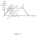
- FIG. 2 is the graph which shows the relationship between the amount of movement and reaching speed of each axis of the robot.
- the abscissa shown in FIG. 2 indicates time and the ordinate indicates speed.
- the resulting line passes through all points, 0, a, b and c as shown by a line 2. More specifically, an axis accelerates until point "a", at a time constant ⁇ 0 moves at a teaching speed Vt, deceleration, and stops at point "c.”
- the area enclosed by the lines formed by points 0, a, b, c , and 0 corresponds to the moving distance.
- the time during which the speed is constant between "a” and "b" becomes shorter.
- the acceleration changes up to a straight line "0d" defined by the time constant ⁇ 0 and a maximum speed Vmax, to form a line 4 containing 0, a1 and c2.
- the locus is indicated by a line 5 containing 0, a2 and c3.
- the maximum speed is Vu; this is referred to as the reaching speed.
- FIG. 3 shows the relationship between the speed of a servomotor and the torque.
- the abscissa indicates a speed (V) and the ordinate indicates a torque (T). Accordingly, when a certain speed V is determined, the corresponding maximum torque Tmax is determined, and the relationship is stored in the robot control device as data for each servomotor of the robot.
- FIG. 4 is the skeleton diagram of the robot.
- the angle at which the robot is set is denoted as ⁇ 0
- the angles of the 1st through 6th axes are denoted as ⁇ 1 through ⁇ 6
- a load weight is denoted as W
- the offset amounts at the centroid of a load are denoted as L1 and L2 .
- the inertia of each axis and a static load torque can be expressed by the following formulae, where the static load torque includes a friction torque and centroid torque.
- the inertia of the 1st axis is denoted as I1, the inertia of the 2nd axis as I2, and inertias of the remaining axes as I3, I4, I5 and I6, respectively, in the same way.
- the static load torque of the 1st axis is denoted as T w1
- the static load torque of the 2nd axis is denoted as T w2
- the static load torques of the remaining axes as T w3 , T w4 , T w5 and T w6 , respectively.
- I1 F1 ( ⁇ 2, ⁇ 3, ⁇ 4, ⁇ 5, ⁇ 6, L1, L2, W)
- I2 F2 ( ⁇ 3, ⁇ 4, ⁇ 5, ⁇ 6, L1, L2, W)
- I3 F3 ( ⁇ 4, ⁇ 5, ⁇ 6, L1, L2, W)
- I4 F4 ( ⁇ 5, ⁇ 6, L1, L2, W)
- I5 F5 ( ⁇ 6, L1, L2, W)
- I6 F6 (L1, L2, W)
- T w1 G1 ( ⁇ 0, ⁇ 1, ⁇ 2, ⁇ 3, ⁇ 4, ⁇ 5, ⁇ 6, L1, L2, W)
- T w2 G2 ( ⁇ 0, ⁇ 1, ⁇ 2, ⁇ 3, ⁇ 4, ⁇ 5, ⁇ 6, L1, L2, W)
- T w3 G3 ( ⁇ 0, ⁇ 1, ⁇ 2, ⁇ 3, ⁇ 4, ⁇ 5, ⁇ 6, L1, L2, W)
- T w4 G4 ( ⁇ 0, ⁇ 1, ⁇ 2, ⁇ 3, ⁇ 4, ⁇ 5, ⁇ 6,
- the functions F1 through F6, and G1 through G6 can be calculated from the structure and posture of the robot. Therefore, when the robot is placed under a particular condition, the inertias I1 through I6 and the static load torques T w1 through T w6 can be determined by an arithmetic operation carried out by the robot control device.
- FIG. 5 is a block diagram showing an outline of the robot control device for implementing the present invention.
- a robot control device 30 is provided with a processor board 31 including a processor 31a, ROM 31b, and RAM 31c, and the processor 31a controls the whole robot control device 30 in accordance with the system program stored in the ROM 31b.
- Data such as the aforementioned L1, L2, and W, an operating program and the like are stored in the RAM 31c.
- a part of the RAM 31c consists of a nonvolatile memory, and the data, the operating program and the like mentioned above are stored in the nonvolatile memory.
- the processor board 31 is connected to a bus 39.
- a digital servo control circuit 32 is connected to the bus 39, and drives servomotors 51, 52, 53, 54, 55 or 56 via a servoamplifier 33 in response to commands issued by the processor board 31.
- the servomotors are incorporated in, and operate the individual axes of, a robot 1.
- a serial port 34 is connected to the bus 39, a teaching console 57 with a display unit, and other RS232C equipment 58.
- the teaching console with the display unit is used to enter an operating program or the like.
- a CRT 36a is connected to the serial port 34.
- a control panel 36b is connected to a digital I/O 35, and signals are output to the outside via the digital I/O 35 and an analog I/O 37. Also, teaching data and operating programs not being used are stored in a large-capacity memory 38.
- the servo control circuit 32 uses a digital servo control circuit, but the above also applies when an analog servo control circuit is used.
- FIG. 1 is a flowchart of the robot control method based on an acceleration/deceleration time constant obtained according to the present invention, as described below.
- the numerals following "S" indicate the step numbers.
- acceleration/deceleration time constant may be determined for each axis.
- the acceleration/deceleration time constant for each axis can be determined from the reaching speed, inertia and the like, which allows an optimum acceleration/deceleration time constant to be determined and the operation time to be reduced.
Landscapes
- Engineering & Computer Science (AREA)
- Human Computer Interaction (AREA)
- Manufacturing & Machinery (AREA)
- Physics & Mathematics (AREA)
- General Physics & Mathematics (AREA)
- Automation & Control Theory (AREA)
- Robotics (AREA)
- Mechanical Engineering (AREA)
- Numerical Control (AREA)
- Manipulator (AREA)
- Control Of Position Or Direction (AREA)
Claims (5)
- Robotersteuerverfahren auf Basis einer Beschleunigungs-/Verzögerungs-Zeitkonstante (τ), dadurch gekennzeichnet, daß die Beschleunigungs-/Verzögerungs-Zeitkonstanten (τ) der Servomotoren auf optimale Werte in jedem Block eingestellt werden, um so den Roboterbetrieb zu steuern, wobei das Einstellen auf optimale Werte folgende Schritte umfaßt:
ein Schritt (S1-S4), in dem eine erreichbare Geschwindigkeit (Vu) aus einer Wegstrecke (X) eines Blockes bestimmt wird;
ein Schritt (S5), bei dem ein Ausgangsmoment (Tmax) eines Servomotors aus der erreichbaren Geschwindigkeit (Vu) bestimmt wird;
ein Schritt (S6), mit dem ein statisches Lastmoment (Twn) von dem Ausgangsmoment (Tmax) abgezogen wird, um ein Beschleunigungsmoment (Tan) zu bestimmen;
ein Schritt (S7), bei dem eine Beschleunigung (an) aus dem Beschleunigungsmoment (Tan) und eine Lastträgheit (In) des Servomotors bestimmt werden; und
ein Schritt (S8), bei dem eine Beschleunigungs/Verzögerungs-Zeitkonstante (τ) aus der Beschleunigung (an) bestimmt wird. - Robotersteuerverfahren mit einer Beschleunigungs/Verzögerungs-Zeitkonstante (τ) gemäß Anspruch 1, bei dem das statische Lastmoment (Twn) als löschbarer Parameter zur Programmierzeit verwendet wird, so daß die Beschleunigungs/Verzögerungs-Zeitkonstante (τ) gemäß der Last des Roboters veränderbar ist.
- Robotersteuerverfahren mit einer Beschleunigungs/Verzögerungs-Zeitkonstante (τ) nach Anspruch 1, bei dem der Beschleunigungswert (an) der Beschleunigungs-/Verzögerungs-Zeitkonstante (τ) mit einer spezifischen Konstante in jedem Programmierpunkt eines Betriebsprogramms eingestellt werden kann.
- Robotersteuerverfahren mit einer Beschleunigungs/Verzögerungs-Zeitkonstante (τ) nach Anspruch 1, bei dem der größte Wert der Beschleunigungs-/Verzögerungs-Zeitkonstanten (τ) der einzelnen Servomotoren zur Steuerung aller Servomotoren ausgewählt wird (S9).
- Robotersteuerverfahren mit einer Beschleunigungs/Verzögerungs-Zeitkonstante (τ) nach Anspruch 1, bei dem die Beschleunigungs-Verzögerungs-Zeitkonstante (τ) für jeden Servomotor getrennt bestimmt wird.
Applications Claiming Priority (3)
| Application Number | Priority Date | Filing Date | Title |
|---|---|---|---|
| JP136007/90 | 1990-05-25 | ||
| JP2136007A JPH0430203A (ja) | 1990-05-25 | 1990-05-25 | ロボットの加減速時定数制御方法 |
| PCT/JP1991/000645 WO1991018717A1 (fr) | 1990-05-25 | 1991-05-15 | Systeme de commande de la constante de temps d'acceleration/deceleration pour robot |
Publications (3)
| Publication Number | Publication Date |
|---|---|
| EP0484551A1 EP0484551A1 (de) | 1992-05-13 |
| EP0484551A4 EP0484551A4 (en) | 1993-03-17 |
| EP0484551B1 true EP0484551B1 (de) | 1995-11-08 |
Family
ID=15165010
Family Applications (1)
| Application Number | Title | Priority Date | Filing Date |
|---|---|---|---|
| EP91909370A Expired - Lifetime EP0484551B1 (de) | 1990-05-25 | 1991-05-15 | Steuersystem für Roboter mit Beschleunigungs- und Verzögerungszeitkonstanten |
Country Status (5)
| Country | Link |
|---|---|
| US (1) | US5325467A (de) |
| EP (1) | EP0484551B1 (de) |
| JP (1) | JPH0430203A (de) |
| DE (1) | DE69114444T2 (de) |
| WO (1) | WO1991018717A1 (de) |
Families Citing this family (16)
| Publication number | Priority date | Publication date | Assignee | Title |
|---|---|---|---|---|
| JP3083870B2 (ja) * | 1991-05-10 | 2000-09-04 | ファナック株式会社 | 数値制御装置 |
| US5708342A (en) * | 1993-05-27 | 1998-01-13 | Fanuc Ltd. | Method of controlling acceleration/deceleration time constants for robot |
| JPH06337708A (ja) * | 1993-05-27 | 1994-12-06 | Fanuc Ltd | ロボットの加減速時定数制御方式 |
| JPH08137524A (ja) * | 1994-11-09 | 1996-05-31 | Fanuc Ltd | ロボットの軌道計画時における時定数の設定方法 |
| US5740327A (en) * | 1994-12-27 | 1998-04-14 | Nec Corporation | Method of and apparatus for robot tip trajectory control |
| JPH0916241A (ja) * | 1995-06-29 | 1997-01-17 | Fanuc Ltd | ロボットの加減速動作の設定方法 |
| WO1997008597A1 (en) * | 1995-08-23 | 1997-03-06 | Fanuc Ltd | Cnc acceleration/deceleration controller and method |
| SE505981C2 (sv) * | 1996-02-14 | 1997-10-27 | Asea Brown Boveri | Förfarande för styrning av en industrirobot med hänsyn till moment och belastning |
| JP3235535B2 (ja) * | 1997-09-26 | 2001-12-04 | 松下電器産業株式会社 | ロボット制御装置とその制御方法 |
| US6900608B2 (en) * | 2003-04-17 | 2005-05-31 | Automated Assemblies Corporation | Apparatus for controlling a motor |
| DE102011010505A1 (de) * | 2011-02-07 | 2012-08-09 | Dürr Systems GmbH | Anpassung der Dynamik zumindest eines Roboters |
| EP2816199B1 (de) * | 2013-06-17 | 2021-09-01 | General Electric Technology GmbH | Steuerung von Instabilitäten aufgrund eines geringen Volumenflusses in Dampfturbinen |
| JP2017052016A (ja) * | 2015-09-07 | 2017-03-16 | セイコーエプソン株式会社 | ロボット、制御装置およびロボットシステム |
| JP6457441B2 (ja) * | 2016-07-12 | 2019-01-23 | ファナック株式会社 | ロボットの重心表示装置、ロボット制御装置およびロボットシミュレーション装置 |
| JP2023050637A (ja) * | 2021-09-30 | 2023-04-11 | ミネベアミツミ株式会社 | ロボットアーム制御装置、ロボットアーム制御システム、及びプログラム |
| CN119974013B (zh) * | 2025-04-01 | 2025-11-25 | 大湾区大学(筹) | 工业机器人速度精准规划方法与控制系统 |
Family Cites Families (14)
| Publication number | Priority date | Publication date | Assignee | Title |
|---|---|---|---|---|
| JPS54123673A (en) * | 1978-03-16 | 1979-09-26 | Fanuc Ltd | Positioning control system |
| JPS57189789A (en) * | 1981-05-16 | 1982-11-22 | Toyama Machine Works | Controller for speed of industrial robot |
| JPS58149188A (ja) * | 1982-02-26 | 1983-09-05 | 神鋼電機株式会社 | 搬送ロボツト |
| JPS5962909A (ja) * | 1982-10-01 | 1984-04-10 | Fanuc Ltd | 加減速装置 |
| JPS59168513A (ja) * | 1983-03-16 | 1984-09-22 | Fanuc Ltd | 加減速制御方式 |
| JPH0632914B2 (ja) * | 1983-06-29 | 1994-05-02 | 新明和工業株式会社 | 産業用ロボツト |
| JPS6231406A (ja) * | 1985-08-02 | 1987-02-10 | Matsushita Electric Ind Co Ltd | 多関節ロボツトの位置決め制御装置 |
| JPS6261104A (ja) * | 1985-09-11 | 1987-03-17 | Fanuc Ltd | 水平関節型ロボツトの加減速制御方式 |
| EP0262600B1 (de) * | 1986-09-29 | 1992-11-25 | Asea Ab | Verfahren und Vorrichtung zur optimalen Parameterregelung von Reglern, die rotierende und/oder lineare Bewegungen eines Industrieroboters steuern |
| US4908556A (en) * | 1986-11-20 | 1990-03-13 | Unimation Inc. | Modular robot control system |
| JPS63273108A (ja) * | 1987-04-30 | 1988-11-10 | Fanuc Ltd | 速度制御装置 |
| JP2707087B2 (ja) * | 1987-09-09 | 1998-01-28 | ファナック株式会社 | ロボット制御装置 |
| JPH0212407A (ja) * | 1988-06-30 | 1990-01-17 | Okuma Mach Works Ltd | 数値制御装置 |
| US5166872A (en) * | 1989-07-17 | 1992-11-24 | Ability Technologies Corporation | System and method for controlling devices through communication processors and pluralities of address-associated device controllers sharing each communication processor |
-
1990
- 1990-05-25 JP JP2136007A patent/JPH0430203A/ja active Pending
-
1991
- 1991-05-15 DE DE69114444T patent/DE69114444T2/de not_active Expired - Fee Related
- 1991-05-15 EP EP91909370A patent/EP0484551B1/de not_active Expired - Lifetime
- 1991-05-15 WO PCT/JP1991/000645 patent/WO1991018717A1/ja not_active Ceased
- 1991-05-15 US US07/820,881 patent/US5325467A/en not_active Expired - Lifetime
Also Published As
| Publication number | Publication date |
|---|---|
| JPH0430203A (ja) | 1992-02-03 |
| WO1991018717A1 (fr) | 1991-12-12 |
| EP0484551A4 (en) | 1993-03-17 |
| US5325467A (en) | 1994-06-28 |
| EP0484551A1 (de) | 1992-05-13 |
| DE69114444D1 (de) | 1995-12-14 |
| DE69114444T2 (de) | 1996-03-21 |
Similar Documents
| Publication | Publication Date | Title |
|---|---|---|
| EP0484551B1 (de) | Steuersystem für Roboter mit Beschleunigungs- und Verzögerungszeitkonstanten | |
| EP0086950B1 (de) | Methode zur Steuerung eines Industrieroboters | |
| EP0881044B1 (de) | Robotersteuerung | |
| US6127792A (en) | Control apparatus for robot | |
| US4873476A (en) | Robot control apparatus for controlling a manipulator through a robot arm having a plurality of axes | |
| EP0766161B1 (de) | Servsystemsteuermethode zum einstellen der flexibilität in einem rechtwinkligen koordinatensystem | |
| EP0519081B1 (de) | Verfahren zum korrigieren der abbiegung eines roboters | |
| EP0538483A1 (de) | Steuerungssystem mit beschleunigungs-/verzögerungszeitkonstante für einen servomotor | |
| US5708342A (en) | Method of controlling acceleration/deceleration time constants for robot | |
| EP0380678B1 (de) | Verfahren zur steuerung der werkzeuglage eines roboters | |
| EP0357778B1 (de) | Verfahren zur regelung der geschwindigkeit für servomotoren | |
| EP0476381B1 (de) | Weginterpolationsverfahren für Roboter | |
| US5314722A (en) | Method of applying a material to a rotating object by using a robot | |
| JPH0991025A (ja) | 動作デューティを考慮したロボットの最短時間制御方法 | |
| EP0240570A1 (de) | Beschleunigungs- und geschwindigkeitsabnahmesteuerungssystem für roboter mit waagerechtem gelenk | |
| EP0271590B1 (de) | Robotersteuerungsanordnung | |
| EP0433461A1 (de) | Nullsetzungsverfahren das einen störungsabschätzungsbeobachter verwendet | |
| JPH06337708A (ja) | ロボットの加減速時定数制御方式 | |
| JPH07244520A (ja) | 干渉トルクを考慮した自動機械の加減速制御方法 | |
| US5751130A (en) | Time constant setting method for a track program of a robot | |
| EP0507980B1 (de) | Regelungsverfahren zur Geschwindigkeitsveränderungsminimierung eines Roboters | |
| JPH08190433A (ja) | 負荷重量推定方法 | |
| JP3588956B2 (ja) | ロボット制御装置 | |
| JP3242190B2 (ja) | 数値制御装置 | |
| JPH07194157A (ja) | サーボモータ制御装置 |
Legal Events
| Date | Code | Title | Description |
|---|---|---|---|
| PUAI | Public reference made under article 153(3) epc to a published international application that has entered the european phase |
Free format text: ORIGINAL CODE: 0009012 |
|
| 17P | Request for examination filed |
Effective date: 19920220 |
|
| AK | Designated contracting states |
Kind code of ref document: A1 Designated state(s): DE IT SE |
|
| A4 | Supplementary search report drawn up and despatched |
Effective date: 19930122 |
|
| AK | Designated contracting states |
Kind code of ref document: A4 Designated state(s): DE IT SE |
|
| 17Q | First examination report despatched |
Effective date: 19950109 |
|
| GRAA | (expected) grant |
Free format text: ORIGINAL CODE: 0009210 |
|
| AK | Designated contracting states |
Kind code of ref document: B1 Designated state(s): DE IT SE |
|
| REF | Corresponds to: |
Ref document number: 69114444 Country of ref document: DE Date of ref document: 19951214 |
|
| ITF | It: translation for a ep patent filed | ||
| PLBE | No opposition filed within time limit |
Free format text: ORIGINAL CODE: 0009261 |
|
| STAA | Information on the status of an ep patent application or granted ep patent |
Free format text: STATUS: NO OPPOSITION FILED WITHIN TIME LIMIT |
|
| 26N | No opposition filed | ||
| PGFP | Annual fee paid to national office [announced via postgrant information from national office to epo] |
Ref country code: DE Payment date: 20080522 Year of fee payment: 18 |
|
| PGFP | Annual fee paid to national office [announced via postgrant information from national office to epo] |
Ref country code: SE Payment date: 20080509 Year of fee payment: 18 |
|
| PGFP | Annual fee paid to national office [announced via postgrant information from national office to epo] |
Ref country code: IT Payment date: 20080527 Year of fee payment: 18 |
|
| PG25 | Lapsed in a contracting state [announced via postgrant information from national office to epo] |
Ref country code: DE Free format text: LAPSE BECAUSE OF NON-PAYMENT OF DUE FEES Effective date: 20091201 |
|
| PG25 | Lapsed in a contracting state [announced via postgrant information from national office to epo] |
Ref country code: IT Free format text: LAPSE BECAUSE OF NON-PAYMENT OF DUE FEES Effective date: 20090515 |
|
| PG25 | Lapsed in a contracting state [announced via postgrant information from national office to epo] |
Ref country code: SE Free format text: LAPSE BECAUSE OF NON-PAYMENT OF DUE FEES Effective date: 20090516 |