EP0484560A1 - Maskierungsmaterial - Google Patents
Maskierungsmaterial Download PDFInfo
- Publication number
- EP0484560A1 EP0484560A1 EP91909837A EP91909837A EP0484560A1 EP 0484560 A1 EP0484560 A1 EP 0484560A1 EP 91909837 A EP91909837 A EP 91909837A EP 91909837 A EP91909837 A EP 91909837A EP 0484560 A1 EP0484560 A1 EP 0484560A1
- Authority
- EP
- European Patent Office
- Prior art keywords
- masking member
- masking
- place
- magnet
- attached
- Prior art date
- Legal status (The legal status is an assumption and is not a legal conclusion. Google has not performed a legal analysis and makes no representation as to the accuracy of the status listed.)
- Withdrawn
Links
Images


Classifications
-
- B—PERFORMING OPERATIONS; TRANSPORTING
- B05—SPRAYING OR ATOMISING IN GENERAL; APPLYING FLUENT MATERIALS TO SURFACES, IN GENERAL
- B05B—SPRAYING APPARATUS; ATOMISING APPARATUS; NOZZLES
- B05B12/00—Arrangements for controlling delivery; Arrangements for controlling the spray area
- B05B12/16—Arrangements for controlling delivery; Arrangements for controlling the spray area for controlling the spray area
- B05B12/20—Masking elements, i.e. elements defining uncoated areas on an object to be coated
- B05B12/26—Masking elements, i.e. elements defining uncoated areas on an object to be coated for masking cavities
Definitions
- the present invention relates to a masking member used to protect a part of the surface of an article from a surface treatment.
- adhesive tape or paper has been used as said masking member used in said two-color coating. Nevertheless, in the case of said adhesive tape, said adhesive tape should be repeatedly attached to cover a masking place having a large area and in the case of said paper, other adhesive tape should be used to attach said paper, and further, said adhesive tape and paper should be cut to fit the size and shape of the masking place and said adhesive tape and paper are apt to easily wrinkle and as a result, the workability to attach said adhesive tape and paper is very inferior. Further, since said adhesive tape and paper are thin and are buried in the coating film after coating, a problem occurs where said adhesive tape or paper is very difficult to remove from the masking place.
- said masking members may be attached to places where said coating should not be effected, for instance, holes such as bolt holes, cable holes, drainage holes, shaft holes and the like, places to which parts are attached such as brackets and the like on said underside of said car-body.
- said adhesive tape or paper has also been used as the masking member in said coating process of the underside of a car-body, and the same problems as above mentioned have arisen.
- a masking member consisting of a plastic sheet molded to correspond with the size and shape of the masking place and an adhesive layer has been provided for the coating of a car-body, bumper and the like (For instance, Jikkai Hei 2-12479).
- said masking member Since said masking member is already molded to correspond with the size and shape of the masking place, said masking member can be attached to said place by said adhesive layer without cutting and since said masking member is rigid, said masking member may not wrinkle when said masking member is attached and as a result, the workability to attach said masking member may be much improved. Further, since said masking member is thick enough, said masking member may not be buried in the coating film and can be easily removed from the masking place.
- a molded plastic foam and a vacuum formed plastic foam sheet has been provided as masking members for the coating of the underside of a car-body (For instance, Jikkai Sho 62-5852).
- Said masking members may be molded in a panel shape, plug shape, clip shape, cap shape, and the like and said panel type masking member is attached to a flat masking place by an adhesive layer, said plug type masking member is attached in a hole, said clip type masking member is attached to a panel masking place by pinching, and said cap type masking member is attached on a projecting masking place.
- Said masking members are also easily attached to and removed from said masking places. Nevertheless, since said masking member consisting of a vacuum formed sheet and said panel type masking member are attached to said masking places by said adhesive layer, when said masking members are once attached to said masking member, it is difficult to move them to adjust the attaching position and to increase the attaching strength to prevent the moving or disconnecting of said masking members during the surface treatment, the bonding strength of said adhesive layer shoud be increased. Nevertheless, when the bonding strength of said adhesive layer is increased, and a large disconnecting force may be necessary when said masking members are removed and a problem that said adhesive layer transfers to the masking place may arise. Especially, in a surface treatment applying high temperature heating, a serious problem that said adhesive layer of said masking members is annealed so as to transfer to said masking place may arise.
- the present invention provides a masking member having (a) magnetic layer (s) to solve said prior problems.
- the magnet (s) is (are) arranged on the back of said masking place and then said masking member is attached to the surface of said masking place to fix said masking member by the magnetic force intermediating said magnetic layer.
- said masking member is attached to said masking place without an adhesive layer.
- said masking member may be attached/removed to/from said masking place by a magnet (s) equipped to a robot intermediating said magnetic layer.
- said masking member is very easily attached/removed to/from said masking place, and automatic attaching and removing can be easily attained, the attaching position of said masking member is easily adjusted and further, said problem of transfer of the adhesive layer is solved.
- Figs. 1 to 4 each show a first embodiment of the present invention and,
- Figs. 5 to 11 each show a second embodiment of the present invention.
- Figs. 12 and 13 each show a third embodiment of the present invention.
- Figs. 14 and 15 each show a fourth embodiment of the present invention.
- Figs. 16 and 17 each show a fifth embodiment of the present invention.
- Figs. 18 and 19 each show a sixth embodiment of the present invention.
- Figs. 20 and 21 each show a seventh embodiment of the present invention.
- Figs. 22 and 23 each show an eighth embodiment of the present invention.
- Figs. 1 to 4 each show a first embodiment of the present invention.
- (11) is a masking member and said masking member is used to protect the air-inlet (21)A of a bumper (21) of a car and has a shape corresponding to the front shape of said air-inlet (21)A and inserting grooves (11)B, (11)C in which crosspieces (21)B and a side piece (21)C of said air-inlet (21)A are respectively inserted are formed in said masking member (11).
- magnetic layers (11)A, (11)A are formed on the upper edge and the lower edge of the back of said masking member by coating a magnetic paint in which a magnetic material such as iron powder and the like is mixed.
- a masking member of the present invention is made of a plastic such as polystyrene, polyethylene, polypropylene, polyvinyl-chloride, polyurethane, melamine resin, urea resin, phenol resin and the like, a reinforced plastic wherein an inorganic filler such as calcium carbonate, talc, bentonite and the like is mixed in said plastic, a foamed plastic of said plastic, a synthetic rubber such as styrene-butadiene rubber, a crylonitrile-butadiene rubber and the like, a natural rubber, a molded fiber material wherein wood fiber, synthetic fiber, natural fiber, inorganic fiber etc. is bound by a binder to mold wood, paper, reclaimed paper, corrugated card-board, metal, and a complex or a laminate of two or more of said materials.
- a plastic such as polystyrene, polyethylene, polypropylene, polyvinyl-chloride, polyurethane, melamine resin,
- (31) is a plastic magnet and said plastic magnet (31) has a shape corresponding to the back shape of said air-inlet (21)A of said bumper (21) and inserting grooves (31)B, (31)C in which said crosspieces (21)B and a side piece (21)C of said air-inlet (21)A are respectively inserted are formed in said plastic magnet (31).
- Said plastic magnet (31) consists of a plastic such as polyethlene, polypropylene, polyvinyl-chloride, acrylonitrile-butadiene-styrene copolymer and the like in whcih a magnet powder such as Sm-Co magnet powder, Nd-Fe magnet powder, ferrite magnet powder, and the like is mixed, and for instance, said plastic mixed with said magnet powder is formed into a sheet and said sheet is molded by a press, vacuum forming and the like to produce said plastic magnet (31) or the pellets of said plastic are mixed with said magnet powder and injection-molded to produce said plastic magnet (31).
- a magnet powder such as Sm-Co magnet powder, Nd-Fe magnet powder, ferrite magnet powder, and the like is mixed, and for instance, said plastic mixed with said magnet powder is formed into a sheet and said sheet is molded by a press, vacuum forming and the like to produce said plastic magnet (31) or the pellets of said plastic are mixed with said magnet powder and injection-molded to produce
- said plastic magnet (31) Prior to coating, said plastic magnet (31) is attached in said air-inlet (21)A of said bumper (21) from the back and said masking member (11) is attached in said air-inlet (21)A from the front.
- said magnetic layer (11)A, (11)A are magnetically attracted to said plastic magnet (31) and said masking member (11) is firmly fixed in said air-inlet (21)A.
- a coating is performed to form a coating film (41) on said bumper (21) excepting said air-inlet (21)A as shown in Fig. 4.
- siad plastic magnet (31) is removed from the back of said air-inlet (21)A and said masking member (11) is removed from the front of said air-inlet (21)A.
- FIGs. 5 to 11 each show a second embodiment of the present invention.
- a masking member (12) of this embodiment has a panel shape and a magnetic layer (12)A is formed on the upper side of said masking member (12) by attaching a foil of a magnetic material such as iron to said upper surface by an adhesive, and an adhesive layer (12)B is formed on the lower side of said masking member (12) and a lacking part (12)C is formed around the circumference of said lower side.
- Said masking member (12) is magnetically attracted to an electro magnet (32) equipped to a robot by saidmagnetic layer (12)A wherein electricity is transmitted to the coil (32)A of said electro magnet (32) as shown in Fig. 6, and said masking member (12) is transported to a flat masking place (22)A of an article (22) and said masking member (12) is attached to said masking place (22)A by said adhesive layer (12)B as shown in Fig. 7. And then, the electricity to said coil (32)A of said electro magnet (32) is cut off to release said masking member (12) from said electro magnet (32) and after then, a coating is performed on the surface of said article (22) to form a coating film (42) as shown in Fig.
- said coating film (42) around the circumference of said masking member (12) is cut by said lacking part (12)C of said masking member (12), said masking member (12) is easily removed without any obstruction of said coating film (42).
- the width W of said lacking part(12)C is more than 1 mm and the height h of said lacking part(12)C is between 0.2 to 10 mm, more preferably 0.5 to 5 mm as shown in Fig. 8.
- said masking member (12) is magnetically attracted by said electro magnet (32) intermediating said magnetic layer (12)A wherein electricity is transmitted to said coil (32)A again as shown in Fig.
- said masking member (12) is magnetically attracted by said electro magnet (32) without any obstruction of said coating film (42) covering said magnitic layer (12)A. Said masking member (12) is transported to the scrapping position and then the electricity to said coil (32)A of said electro magnet (32) is cut off to release said masking member (12) from said electro magnet (32) as shown in Fig. 11.
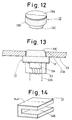
- FIGs. 12 and 13 each show a third embodiment of the present invention.
- a masking member (13) of the present invention has a plug shape consisting of a flange part (13)B and a tapering inserting part (13)C, and a magnetic layer (13)A is formed on the upper side of said flange part (13)B by scattering a magnetic powder such as iron powder and the like after an adhesive is coated on said upper side of said flange part (13)B.
- Said masking member (13) is magnetically attracted by an electro magnet (33) intermediating said magnetic layer (13)A wherein electricity is transmitted to the coil (33)A of said electro magnet (33), the same as in the prior embodiment to insert said masking member (13) into a hole (23)A as a masking place of an article (23) as shown in Fig. 13, and after the surface treatment, said masking member (13) is removed from said hole (23)A by the magnetic attraction of said electro magnet (32), the same as in the prior embodiment.
- FIGs. 14 and 15 each show a fourth embodiment of the present invention.
- a masking member (14) of this embodiment has a clip shape having an inserting groove (14)B, and a magnetic layer (14)A is formed on the outside of said masking member (14) by attaching a foil of a magnetic material to said outside.
- Said masking member (14) is magnetically attracted by a permanent magnet (34) intermediating said magnetic layer (14)A wherein electricity is transmitted to attach said masking member (14) to a masking place (24)A having a panel shape of an article (24) by inserting said masking place (24)A into said insertin g groove (14)B as shown in Fig. 15, and after the surfacetreatment, said masking member (14) is removed from said masking place (24)A by the magnetic attraction of said permanent magnet (34), the same as in the prior embodiments.
- FIGs. 16 and 17 each show a fifth embodiment of the present invention.
- a masking member (15) of this embodiment has a cylinderical shape and an inserting hole (15)B is formed in said masking member (15) and a magnetic layer (15)A is formed on the upper side of said masking member (15) by attaching a foil of a magnetic material such as iron and the like on said upper side.
- Said masking member (15) is magnetically attracted by an electro magnet (35) intermediating said magnetic layer (15)A wherein electricity is transmitted to the coil (35)A of said electro magnet (35), the same as in the second and third embodiments to attach said masking member (15) on a projecting masking place (25)A of an article (25) by inserting said masking place (25)A into said inserting hole (15)B as shown in Fig. 17, and said masking member (15) is removed from said masking place (25)A by the magnetic attraction of said electro magnet (35), the same as in the second and third embodiments.
- FIGs. 18 and 19 each show a sixth embodiment of the present invention.
- a masking member (16) of this embodiment has a vessel shape and a magnetic layer (16) A is formed on the inside of the bottom of said masking member (16) by coating a magnetic paint, the same as in the first embodiment, and an adhesive layer (16)B is formed on the outside of said bottom and a flange part (16)C is formed outwardly from the upper edge of said masking member (16).
- Said masking member (16) is magnetically attracted by an electro magnet (36) intermediating said magnetic layer (16)A wherein electricity is transmitted to the coil (36)A of said electro magnet (36), the same as in the prior embodiments to attach said masking member (16) to a flat masking place (26)A of an article (26) by said adhesive layer (16)B as shown in Fig. 19, and after the surface treatment, said masking member (16) is removed from said masking place (26)A by the magnetic attraction of said electro magnet (36), the same as in the prior embodiments.
- FIGs. 20 and 21 each show a seventh embodiment of the present invention.
- a masking member (17) of this embodiment has a vessel shape forming an inserting hole (17)B on the inside of said masking member (17) and a magnetic layer (17)A is formed on the outside of the bottom of said masking member (17) by attaching a foil of a magnetic material, the same as in the second embodiment to said outside of said bottom by an adhesive, and a flange part (17)C is formed outwardly from the upper edge of said masking memgber (17).
- Said masking member (17) is magnetically attracted by an electro magnet (37) intermediating said magnetic layer (17)A wherein electricity is transmitted to the coil (37)A of said electro magnet (37), the same as in the prior embodiments to attach said masking member (17) to a projecting masking place (27)A of an article (27) by inserting said masking place (27)A into said inserting hole (17)B as shown in Fig. 21, and after the sufrace treatment, said masking member (17) is removed from said masking place (27)A by the magnetic attraction of said electro magnet (37) the same as the prior embodiment.
- FIGs. 22 and 23 each show a eigth embodiment of the present invention.
- a masking member (18) of this embodiment consists of an inserting part (18)B having a vessel shape and a flange part (18)C formed from the upper edge of said inserting part (18)B having a vessel shape and a magnetic layer (18)A is formed on the upper side of said flange part (18)C, the same as in the prior embodiments.
- Said masking member (18) is magnetically attracted by an electro magnet (38) intermediating said magnetic layer (18)A wherein electricity is transmitted to the coil (38)A of said electro magnet (38), the same as in the prior embodiments to attach said masking member (18) in a hole (28)A of an article (28) as shown in Fig. 23, and after the sufrace treatment, said masking member (18) is removed from said masking place (28)A by the magnetic attraction of said electro magnet (38), the same as in the prior embodiments.
Landscapes
- Details Or Accessories Of Spraying Plant Or Apparatus (AREA)
Applications Claiming Priority (2)
| Application Number | Priority Date | Filing Date | Title |
|---|---|---|---|
| JP137505/90 | 1990-05-28 | ||
| JP2137505A JPH0429771A (ja) | 1990-05-28 | 1990-05-28 | マスキング材 |
Publications (2)
| Publication Number | Publication Date |
|---|---|
| EP0484560A1 true EP0484560A1 (de) | 1992-05-13 |
| EP0484560A4 EP0484560A4 (en) | 1992-08-12 |
Family
ID=15200237
Family Applications (1)
| Application Number | Title | Priority Date | Filing Date |
|---|---|---|---|
| EP19910909837 Withdrawn EP0484560A4 (en) | 1990-05-28 | 1991-05-23 | Masking material |
Country Status (4)
| Country | Link |
|---|---|
| EP (1) | EP0484560A4 (de) |
| JP (1) | JPH0429771A (de) |
| CA (1) | CA2059664A1 (de) |
| WO (1) | WO1991018678A1 (de) |
Cited By (2)
| Publication number | Priority date | Publication date | Assignee | Title |
|---|---|---|---|---|
| FR2751567A1 (fr) * | 1996-07-26 | 1998-01-30 | Manducher Sa | Dispositif de masquage d'une piece pour l'application electrostatique d'un appret poudre sur sa bordure |
| CN105018991A (zh) * | 2014-04-30 | 2015-11-04 | 梅西耶-布加蒂-道提公司 | 保护装置及实施这种装置的方法 |
Families Citing this family (1)
| Publication number | Priority date | Publication date | Assignee | Title |
|---|---|---|---|---|
| CN114733665A (zh) * | 2022-03-07 | 2022-07-12 | 昆山和能五金塑胶科技有限公司 | 一种喷涂用治具及喷涂设备和喷涂方法 |
Family Cites Families (2)
| Publication number | Priority date | Publication date | Assignee | Title |
|---|---|---|---|---|
| JPS60140673U (ja) * | 1984-02-27 | 1985-09-18 | 住友金属工業株式会社 | 鋼板の縁取り塗装用遮蔽板 |
| JPS62126274U (de) * | 1986-01-31 | 1987-08-11 |
-
1990
- 1990-05-28 JP JP2137505A patent/JPH0429771A/ja active Pending
-
1991
- 1991-05-23 EP EP19910909837 patent/EP0484560A4/en not_active Withdrawn
- 1991-05-23 WO PCT/JP1991/000696 patent/WO1991018678A1/ja not_active Ceased
- 1991-05-23 CA CA002059664A patent/CA2059664A1/en not_active Abandoned
Cited By (4)
| Publication number | Priority date | Publication date | Assignee | Title |
|---|---|---|---|---|
| FR2751567A1 (fr) * | 1996-07-26 | 1998-01-30 | Manducher Sa | Dispositif de masquage d'une piece pour l'application electrostatique d'un appret poudre sur sa bordure |
| CN105018991A (zh) * | 2014-04-30 | 2015-11-04 | 梅西耶-布加蒂-道提公司 | 保护装置及实施这种装置的方法 |
| EP2954957A1 (de) * | 2014-04-30 | 2015-12-16 | Messier-Bugatti-Dowty | Schutzvorrichtung und verfahren zur verwendung einer solchen vorrichtung |
| CN105018991B (zh) * | 2014-04-30 | 2019-02-26 | 梅西耶-布加蒂-道提公司 | 保护装置及实施这种装置的方法 |
Also Published As
| Publication number | Publication date |
|---|---|
| EP0484560A4 (en) | 1992-08-12 |
| CA2059664A1 (en) | 1991-11-29 |
| JPH0429771A (ja) | 1992-01-31 |
| WO1991018678A1 (en) | 1991-12-12 |
Similar Documents
| Publication | Publication Date | Title |
|---|---|---|
| EP0262946A2 (de) | Maske | |
| US6148487A (en) | Laminated self-gripping tape, molded product, and method of manufacturing a molded article including a self-gripping tape | |
| CA1280648C (en) | Corrosion, sound, and vibration-proof method for metal structures | |
| CA1255164A (en) | Expanding and shrinking member | |
| EP0368615B1 (de) | Abdeckelement | |
| EP0207720B1 (de) | Maske | |
| KR930001191Y1 (ko) | 마스킹재 | |
| US5270085A (en) | Masking member | |
| EP0484560A1 (de) | Maskierungsmaterial | |
| EP0367259B1 (de) | Maskenteil | |
| EP0320225A2 (de) | Dekorationsgegenstand und dessen Herstellungsverfahren | |
| US20040006903A1 (en) | Manipulable foam mat with magnetic backing | |
| JPS62152945A (ja) | 磁石入りトツプトリム | |
| EP0483377A1 (de) | Abdeckmaske | |
| US4898758A (en) | Paint mask | |
| EP0384696B1 (de) | Abdeckelement | |
| EP0367261B1 (de) | Maskenteil | |
| IL179588A (en) | Injection molding method and system and molded products manufactured thereby | |
| EP0606694A1 (de) | Abdeckung | |
| JPS6463111A (en) | Method for integrally forming composite formed item | |
| EP0370796A1 (de) | Isolierverfahren für metallische Gegenstände gegen Korrosion, Schall und Vibration | |
| JPH03199473A (ja) | 車両用カーペットの製造方法 | |
| JPH04216100A (ja) | 化粧材および化粧シート | |
| KR101159622B1 (ko) | 다층 커버를 갖는 파스너 조립체 | |
| EP0387998A1 (de) | Vorrichtung zur Maskierung |
Legal Events
| Date | Code | Title | Description |
|---|---|---|---|
| PUAI | Public reference made under article 153(3) epc to a published international application that has entered the european phase |
Free format text: ORIGINAL CODE: 0009012 |
|
| 17P | Request for examination filed |
Effective date: 19920203 |
|
| AK | Designated contracting states |
Kind code of ref document: A1 Designated state(s): DE FR GB IT SE |
|
| A4 | Supplementary search report drawn up and despatched |
Effective date: 19920626 |
|
| AK | Designated contracting states |
Kind code of ref document: A4 Designated state(s): DE FR GB IT SE |
|
| 17Q | First examination report despatched |
Effective date: 19931005 |
|
| STAA | Information on the status of an ep patent application or granted ep patent |
Free format text: STATUS: THE APPLICATION IS DEEMED TO BE WITHDRAWN |
|
| 18D | Application deemed to be withdrawn |
Effective date: 19940216 |