EP0484588B1 - Matrice avec coulisseau - Google Patents
Matrice avec coulisseau Download PDFInfo
- Publication number
- EP0484588B1 EP0484588B1 EP90121507A EP90121507A EP0484588B1 EP 0484588 B1 EP0484588 B1 EP 0484588B1 EP 90121507 A EP90121507 A EP 90121507A EP 90121507 A EP90121507 A EP 90121507A EP 0484588 B1 EP0484588 B1 EP 0484588B1
- Authority
- EP
- European Patent Office
- Prior art keywords
- slide cam
- cam
- die
- base
- guide portion
- Prior art date
- Legal status (The legal status is an assumption and is not a legal conclusion. Google has not performed a legal analysis and makes no representation as to the accuracy of the status listed.)
- Expired - Lifetime
Links
Images


Classifications
-
- B—PERFORMING OPERATIONS; TRANSPORTING
- B21—MECHANICAL METAL-WORKING WITHOUT ESSENTIALLY REMOVING MATERIAL; PUNCHING METAL
- B21D—WORKING OR PROCESSING OF SHEET METAL OR METAL TUBES, RODS OR PROFILES WITHOUT ESSENTIALLY REMOVING MATERIAL; PUNCHING METAL
- B21D28/00—Shaping by press-cutting; Perforating
- B21D28/24—Perforating, i.e. punching holes
- B21D28/32—Perforating, i.e. punching holes in other articles of special shape
-
- Y—GENERAL TAGGING OF NEW TECHNOLOGICAL DEVELOPMENTS; GENERAL TAGGING OF CROSS-SECTIONAL TECHNOLOGIES SPANNING OVER SEVERAL SECTIONS OF THE IPC; TECHNICAL SUBJECTS COVERED BY FORMER USPC CROSS-REFERENCE ART COLLECTIONS [XRACs] AND DIGESTS
- Y10—TECHNICAL SUBJECTS COVERED BY FORMER USPC
- Y10T—TECHNICAL SUBJECTS COVERED BY FORMER US CLASSIFICATION
- Y10T83/00—Cutting
- Y10T83/869—Means to drive or to guide tool
- Y10T83/8776—Constantly urged tool or tool support [e.g., spring biased]
- Y10T83/8785—Through return [noncutting] stroke
-
- Y—GENERAL TAGGING OF NEW TECHNOLOGICAL DEVELOPMENTS; GENERAL TAGGING OF CROSS-SECTIONAL TECHNOLOGIES SPANNING OVER SEVERAL SECTIONS OF THE IPC; TECHNICAL SUBJECTS COVERED BY FORMER USPC CROSS-REFERENCE ART COLLECTIONS [XRACs] AND DIGESTS
- Y10—TECHNICAL SUBJECTS COVERED BY FORMER USPC
- Y10T—TECHNICAL SUBJECTS COVERED BY FORMER US CLASSIFICATION
- Y10T83/00—Cutting
- Y10T83/869—Means to drive or to guide tool
- Y10T83/8821—With simple rectilinear reciprocating motion only
- Y10T83/8828—Plural tools with same drive means
- Y10T83/8831—Plural distinct cutting edges on same support
-
- Y—GENERAL TAGGING OF NEW TECHNOLOGICAL DEVELOPMENTS; GENERAL TAGGING OF CROSS-SECTIONAL TECHNOLOGIES SPANNING OVER SEVERAL SECTIONS OF THE IPC; TECHNICAL SUBJECTS COVERED BY FORMER USPC CROSS-REFERENCE ART COLLECTIONS [XRACs] AND DIGESTS
- Y10—TECHNICAL SUBJECTS COVERED BY FORMER USPC
- Y10T—TECHNICAL SUBJECTS COVERED BY FORMER US CLASSIFICATION
- Y10T83/00—Cutting
- Y10T83/869—Means to drive or to guide tool
- Y10T83/8821—With simple rectilinear reciprocating motion only
- Y10T83/8841—Tool driver movable relative to tool support
- Y10T83/8853—Including details of guide for tool or tool support
Definitions
- the present invention relates to a die including a slide cam.
- a lower die and an upper die are mounted respectively on a bed and a ram of a pressing machine so that piercing and forming processings can be accomplished by ascending and descending the upper die. Since the upper die is moved up and down, the transverse machining is effected by converting the vertical machining force to a horizontal force by using a cam member.
- a positioning member 104 which positions the work 103 on a base plate 102 is secured.
- a driven cam 107 including a punch 106 is slidably arranged.
- a heel 108 is secured to the rear side of the driven cam 107.
- a coil spring 109 is installed around the top side of a rod 110 which is threaded into the driven cam 107, passing through the heel 108, and one end of the coil spring 109 is in contact with the heel 108.
- a nut 112 is screwed on to abut the other end of the coil spring 109 via a washer 111, to bias the elements such that the driven cam 107 is drawn back after piercing the work 103.
- a driving cam 118 is secured to a base plate 117 of the upper die 116 at a position to oppose the driven cam 107.
- the driving cam 118 moves the driven cam 107 forward against the biasing force of the coil spring 109 to pierce the hole 105 in the work 103 by the punch 106 and a die 125, and when the upper die 116 is ascended, the driven cam 107 is moved rearward by the biasing force of the coil spring 109.
- the driven cam 107 including the punch 106 slides on the base plate 102 while approaching, and parting from, the work 104.
- the driving cam 107 has to slide accurately to pierce by the punch 106 and die 125; therefore, flanges 121 project from lower opposite sides of the driven cam 107, and side guide plates 122 and upper guide plates 123 for guiding the flanges 121 are fixed to the base plate 102.
- the side guide plates 122 for guiding the side faces of the flanges 121 extending from the sides of the driven cam body 107a, and the upper guide plates 123 for guiding the upper faces of the flanges 121 are provided. Since flange 121, side guide plate 122 and upper guide plate 123 are provided, an extended length l is provided respectively on opposite sides of the body portion 107a of the driven cam 107, the length l being usually about 100 to 150 mm at a minimum. Thereby, a large space is occupied on the base plate 102 of the lower die 101 of the press die.
- a large space is occupied when a cam mechanism is provided on the die. Since the large space is occupied by providing the cam mechanism, the die size is restricted by the bed area of the pressing machine, and the necessary members cannot be installed on the die; therefore, sometimes the number of machining processes must be increased and the die has to be added.
- a wear plate 124 provided on the tip of the flange 121 projecting from the side of the body portion 107a of the driven cam 107 wears as the driven cam 107 repeats the sliding operations, producing a gap between the side guide plate 122; thus, the driven cam 107 cannot slide linearly and tends to meander owing to the existence of the gap.
- the punch 106 installed on the driven cam 107 also moves similarly in a serpentine fashion; thus, the punch 106 is unable to punch in the state wherein a proper clearance is maintained circularly around the die 125, producing burrs around the punched hole, whereby a high quality punching becomes impossible. Besides, due to the punching by the punch 106 and die 125 which produce the burrs, edges of the punch 106 and die 125 are damaged.
- a die as mentioned in the preamble of claim 1 is disclosed in JP-A-61007024.
- Claim 2 sets out a particular embodiment of the invention.
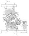
- An example described below involves a work to be pierced and trimmed at its lower end.
- a positioning member 4 which positions the work (workpiece) 3 is fixed by means of bolts 5.
- a driving cam 8 is fixed by bolts 9, on which driving cam a guide member 6 whose upper surface is formed as an inclined plane which slants as approaching (towards) the positioning member 4 so as to contact to a V-shaped groove, is installed with bolts 7.
- a slide cam base 13 On a base plate 12 of an upper die 11 opposing the driving cam 8, a slide cam base 13 is secured by bolts 14.
- the top of the slide cam base 13 is formed as a tetrahedral guide portion 16 which is generally quadrangular in cross-section and provided with the crest line 15 at the lower end, and having an inclined plane which, symmetrically with the inclined plane of the driving cam 8, slants upward as approaching the positioning member 4.
- a slide cam 17 which holds and slidably supports the tetrahedral guide portion 16 of the slide cam base 13 and slides on the guide member 6 of the driving cam 8 is provided.
- the slide cam 17 comprises a machining member 19 to which a V-shaped groove member 18, punch and cutting edge are mounted.
- the V-shaped groove member 18 is positioned by a key 20 driven into an opposing face of the machining member 19, and fixed by bolts 22 by raising a stopper 21.
- the upper end of the slide cam 17 is formed with a V-shaped groove which has the same inclined plane as that of the tetrahedral guide portion 16 of the slide cam base 13 and receives the tetrahedral guide portion 16, and provided with wear plates 23 fixed with bolts 24 to support lower planes 25 of the tetrahedral guide portion 16 of the slide cam base 13, upper planes 26 being urged by biasing plates 28 fixed by bolts 27 to the slide cam 17 which is arranged to be slidable on the tetrahedral guide portion 16 of the slide cam base 13.
- a sliding member 29 which slides on the guide member 6 of the driving cam 8 by having its V-shaped groove in engagement therewith, is fixed by bolts 30.
- a mounting plate 41 is mounted by a bolt 42.
- a punch 43 is installed by fixing a punch plate 44 to the mounting plate 41 by means of a bolt 45.
- a trimming edge 51 is fixed to the mounting plate 41 by means of a bolt 46.
- Numeral 49 generally indicates a die which is engaged with the punch 43 for piercing
- numeral 50 denotes a cutting edge which trims the edges of the work 3 in cooperation with the trimming edge 45.
- a retaining hole 61 is formed in the rear end portion of the tetrahedral guide portion 16 of the slide cam base 13, and a support plate 62 is disposed at a position opposing the retaining hole 61, and secured to the slide cam 17 by means of a bolt 63.
- An elastic body 64 such as a coil spring is provided between the retaining hole 61 and the support plate 62.
- the stopper 21 raised on the slide cam 17 is engaged with an end portion 65a of a stopping groove 65 formed in the crest line at the lower portion of the tetrahedral guide portion 16 of the slide cam base 13.
- a safety stopper 66 is screwed into the retaining hole 61 to fix the position of the coil spring; at the same time, the safety stopper 66 is extended through the support plate 62 and provided with a head portion 66a at its end, so as to stop the stopper 21 by the support plate 62 which collides against the head portion 66a, in case the stopper 21 does not stop at the end portion 65a of the stopping groove 65.
- a return plate 71 is secured to the slide cam 17 by bolts 72, and engaged with the driving cam 8 at the lower end thereof.
- Fig. 4 shows a top dead point where the slide cam 17, slidably disposed on the tetrahedral guide portion 16 of the slide cam base 13 installed on the base plate 12 of the upper die 11, is in contact with the stopper 21.
- Fig. 1 The state wherein piercing and trimming are effected by the punch 43 and the trimming edge 51, and the upper die 11 is at the bottom dead point, is shown in Fig. 1.
- the return plate 71 Since the return plate 71 is provided on the slide cam 17, when the slide cam 17 fails to retreat for some reason, the return plate 71 is engaged with the driving cam 8 to forcibly retreat the slide cam 17.
- slide cam base 13, slide cam 17 and driving cam 8 are arranged in order from top to bottom
- they may be arranged in order of the driving cam 8, slide cam 17 and slide cam base 13 from top to bottom.
- a unit comprising the slide cam base 13, slide cam 17 and driving cam 8 may be used reversely.
- a cam mechanism can be constituted without providing cam guiding flanges, side guide plates and upper guide plates, and the cam mechanism can be provided on the die in a minimum space.
- machining can be effected from the direction suitable to the curved surface or from the normal direction to the curved surface, so that in case of piercing a circular hole, it can be finished in a true circle and not in an ellipse, thereby improving machining quality.
- a die can be prepared to be smaller and lighter and at lower cost. Since the die is small, it can be produced using small-size machine tools and cranes in die making facilities.
- the cam since the slide cam is held and slidably supported by the slide cam base, even when the sliding portion is worn after long operation of the die, the cam does not meander like the conventional die, but moves linearly; thus, a high quality pressing work can be accomplished. Besides, since the slide cam base moves in the linear direction precisely, edges of the punch, die and cutting edge do not break. In the embodiment of the present invention, since the sliding faces of the slide cam and the driving cam are formed with the V-shaped groove, there is no possibility that the cam meanders.
- a sliding mechanism is provided in the center portion of the cam, it can be divided into small sections, and as compared with the conventional cam in which the flanges are extended from opposite sides, the cam divided into the small sections can be held and supported at many locations, so that, when compared with the conventional large member in which the cam is held only on opposite sides, the cam can be held securely.
- the present invention can be applied immediately to the machining of works having various sizes.
Landscapes
- Engineering & Computer Science (AREA)
- Mechanical Engineering (AREA)
- Punching Or Piercing (AREA)
- Mounting, Exchange, And Manufacturing Of Dies (AREA)
- Treatment And Processing Of Natural Fur Or Leather (AREA)
- Control Of Cutting Processes (AREA)
Claims (2)
- Matrice pourvue d'une came coulissante (17), dans laquelle :
un élément de positionnement (4) qui positionne la pièce (3) est fixé sur une plaque de base (2) de la matrice inférieure (1),
une came d'entraînement (8) est fixée sur ladite plaque de base (2) au voisinage dudit élément de positionnement (4), et comprend un élément de guidage (6), dont la surface supérieure s'incline vers le bas en s'approchant dudit élément de positionnement (4), ladite surface supérieure dudit élément de guidage (6) étant en contact avec une première rainure en forme de "V",
une base de came coulissante (13) est fixée sur une seconde plaque de base (12) d'une matrice supérieure (11) en face de ladite came d'entraînement (8), la partie inférieure de ladite base de came coulissante (13) étant usinée pour constituer une partie de guidage (16) laquelle s'incline vers le haut en s'approchant dudit élément de positionnement (4),
ladite came coulissante (17) maintient et supporte en coulissement ladite partie de guidage (16) de ladite base de came coulissante (13) et coulisse sur ledit élément de guidage (6) de ladite came d'entraînement (8),
ladite came coulissante (17) comprend un élément d'usinage (19) sur lequel sont montés des outils d'usinage appropriés, des moyens (61,62,64) étant prévus pour solliciter de manière élastique ladite came coulissante (17) dans une direction qui l'éloigne dudit élément de positionnement (4),
caractérisée en ce que :
ladite première rainure en forme de "V", avec laquelle ladite surface supérieure dudit élément de guidage (6) vient en contact, est formée dans un élément coulissant (29) fixé sur la surface inférieure dudit élément d'usinage (19),
ladite partie de guidage (16) a une forme tétraédrique et présente une ligne de crête (15) à son extrémité inférieure,
une seconde rainure en forme de "V" est formée sur la partie supérieure d'un élément de rainure en forme de "V" (18) monté à l'extrémité supérieure dudit élément d'usinage (19) et constitue une surface supérieure de ladite came coulissante (17), ledit élément de rainure en forme de "V" (18) recevant par sa partie supérieure, qui s'incline conformément à ladite partie de guidage de forme tétraédrique (16), ladite partie de forme tétraédrique (16) de ladite base de came coulissante (13) et étant pourvu de plaques d'usure (23) coopérant avec les surfaces supports inférieures (25) de ladite partie de guidage tétraédrique (16) de ladite base de came coulissante (13), et
les surfaces supérieures (26) de ladite partie de guidage tétraédrique (16) de ladite base de came coulissante (13) sont sollicitées par des plaques de sollicitation (28) fixées sur ladite came coulissante (17). - came comme revendiquée dans la revendication 1, caractérisée en ce que :
un orifice de retenue (61) est formé à la partie d'extrémité (16) de ladite partie de guidage tétraédrique (16) de ladite base de came de guidage (13) qui est située face à l'élément de positionnement (4),
une plaque support (62) est fixée sur ladite came coulissante (17) et s'étend jusqu'à une position située en face dudit orifice de retenue (61), et
une pièce élastique (64), telle qu'un ressort en spirale, est montée entre ledit orifice de retenue (61) et ladite plaque support (62).
Priority Applications (4)
| Application Number | Priority Date | Filing Date | Title |
|---|---|---|---|
| DE69018082T DE69018082T2 (de) | 1990-11-09 | 1990-11-09 | Gesenk mit Führungsschlitten. |
| ES90121507T ES2069654T3 (es) | 1990-11-09 | 1990-11-09 | Matriz con leva deslizante. |
| EP90121507A EP0484588B1 (fr) | 1990-11-09 | 1990-11-09 | Matrice avec coulisseau |
| US07/631,150 US5101705A (en) | 1990-11-09 | 1990-12-20 | Die including slide cam |
Applications Claiming Priority (1)
| Application Number | Priority Date | Filing Date | Title |
|---|---|---|---|
| EP90121507A EP0484588B1 (fr) | 1990-11-09 | 1990-11-09 | Matrice avec coulisseau |
Publications (2)
| Publication Number | Publication Date |
|---|---|
| EP0484588A1 EP0484588A1 (fr) | 1992-05-13 |
| EP0484588B1 true EP0484588B1 (fr) | 1995-03-22 |
Family
ID=8204704
Family Applications (1)
| Application Number | Title | Priority Date | Filing Date |
|---|---|---|---|
| EP90121507A Expired - Lifetime EP0484588B1 (fr) | 1990-11-09 | 1990-11-09 | Matrice avec coulisseau |
Country Status (4)
| Country | Link |
|---|---|
| US (1) | US5101705A (fr) |
| EP (1) | EP0484588B1 (fr) |
| DE (1) | DE69018082T2 (fr) |
| ES (1) | ES2069654T3 (fr) |
Families Citing this family (61)
| Publication number | Priority date | Publication date | Assignee | Title |
|---|---|---|---|---|
| US5269167A (en) * | 1992-01-09 | 1993-12-14 | Connell Limited Partnership | Universal aerial cam unit |
| US5487296A (en) * | 1992-01-09 | 1996-01-30 | Connell Limited Partnership | Univers cam unit |
| CA2073204C (fr) * | 1992-07-06 | 1999-08-24 | Mitsuo Matsuoka | Configuration d'outil a cames visant a reduire le niveau du bruit |
| US5307715A (en) * | 1992-08-31 | 1994-05-03 | Caterpillar Inc. | Angle punching die arrangement |
| ES2080008B1 (es) * | 1993-12-13 | 1997-10-16 | Bonet Jose Lozano | Unidad de punzonado lateral |
| JP3610606B2 (ja) * | 1994-12-27 | 2005-01-19 | オイレス工業株式会社 | プレス用カム型 |
| WO1997004894A1 (fr) * | 1995-07-31 | 1997-02-13 | Oiles Corporation | Came pour matrice de presse a estamper le metal |
| JPH10235437A (ja) * | 1997-02-25 | 1998-09-08 | Sankyo Oiruresu Kogyo Kk | プレス金型用のカムユニット |
| JP2880490B1 (ja) * | 1997-11-14 | 1999-04-12 | ユミックス株式会社 | プレス装置 |
| DE19753549C2 (de) * | 1997-12-03 | 2000-02-17 | Harald Weigelt | Keiltrieb |
| US6189360B1 (en) * | 1998-06-15 | 2001-02-20 | Sanyo Machine America Corp. | Metal forming machine |
| US5884521A (en) * | 1998-07-10 | 1999-03-23 | Lamina, Inc. | High performance aerial and die mount cams |
| JP3757635B2 (ja) * | 1998-08-26 | 2006-03-22 | オイレス工業株式会社 | カム装置 |
| DE19855919A1 (de) * | 1998-12-03 | 2000-06-08 | Umix Co Ltd | Preßvorrichtung |
| DE19860178C1 (de) * | 1998-12-24 | 2000-05-11 | Harald Weigelt | Keiltrieb zur Umlenkung einer vertikalen Preßkraft |
| US6170375B1 (en) * | 1999-03-17 | 2001-01-09 | Lamina, Inc. | Bump cam |
| JP3072095B1 (ja) * | 1999-06-25 | 2000-07-31 | ユミックス株式会社 | プレス装置 |
| JP2001137947A (ja) * | 1999-11-15 | 2001-05-22 | Umix Kk | プレス金型の付勢装置 |
| ATE271942T1 (de) * | 2000-03-17 | 2004-08-15 | Sankyo Oilless Ind Inc | Selbstzentrierender führungsschlitten |
| ATE337165T1 (de) * | 2000-10-13 | 2006-09-15 | Harald Weigelt | Keiltrieb |
| US7337649B2 (en) * | 2002-02-11 | 2008-03-04 | Anchor Lamina, Inc. | Press action simulator for aerial cam set up |
| US6672126B2 (en) | 2002-03-25 | 2004-01-06 | The Gates Corporation | Stepped cam die |
| JP3540308B2 (ja) * | 2002-05-16 | 2004-07-07 | ユミックス株式会社 | スライドカム型 |
| US7258030B2 (en) * | 2003-01-21 | 2007-08-21 | Syron Engineering & Manufacturing, Llc | Failsafe element for rotary cam unit used in a flanged die |
| JP2004249355A (ja) * | 2003-02-21 | 2004-09-09 | Sankyo Oilless Industry Inc | モジュールカムと加工具の取付位置調整方法 |
| JP2005144493A (ja) * | 2003-11-14 | 2005-06-09 | Umix Co Ltd | 複動カム型 |
| US6978651B2 (en) * | 2004-06-01 | 2005-12-27 | Anchor Lamina America, Inc. | Roller cam |
| US6990844B1 (en) | 2004-07-27 | 2006-01-31 | Anchor Lamina America, Inc. | Narrow aerial and die-mount cams |
| US7523634B2 (en) * | 2004-08-24 | 2009-04-28 | Helical Cam, Llc. | Forming die having filler cam assembly |
| US7431502B2 (en) * | 2004-09-15 | 2008-10-07 | Anchor Lamina America, Inc. | Universal cam slide |
| CN100486727C (zh) * | 2004-11-18 | 2009-05-13 | 丹利·耶姆有限公司 | 装配压床的靠模 |
| US7191635B2 (en) * | 2004-11-18 | 2007-03-20 | Danly Iem, Llc | Press mounted cam |
| DE102005029140B4 (de) * | 2005-06-23 | 2008-04-03 | Elke Weigelt | Werkzeugbefestigungseinrichtung für einen Keiltrieb |
| DE102006036654B4 (de) * | 2006-08-03 | 2008-12-04 | Harald Weigelt | Keiltrieb mit Zwangsrückholeinrichtung |
| US8171821B2 (en) * | 2006-09-28 | 2012-05-08 | Helical Cam, Llc | Corner cam assembly |
| US8430385B2 (en) | 2007-09-24 | 2013-04-30 | Harald Weigelt | Wedge drive with slider receiving means |
| DE102008006864A1 (de) * | 2008-01-31 | 2009-08-06 | Mühlhoff Umformtechnik GmbH | Verfahren und Vorrichtung zur Lochung eines Werkstücks |
| DE102008061420B9 (de) | 2008-12-10 | 2011-02-10 | voestalpine Gießerei Linz GmbH | Keiltrieb |
| JP5448520B2 (ja) * | 2009-03-27 | 2014-03-19 | 三協オイルレス工業株式会社 | カム装置のカムスライダー用緩衝材の取付構造 |
| JP2011140048A (ja) * | 2010-01-08 | 2011-07-21 | Sankyo Oilless Industry Inc | カム装置 |
| CN102000741A (zh) * | 2010-11-19 | 2011-04-06 | 青岛诺义信模具部件有限公司 | 多功能拼装斜楔 |
| CN102284620B (zh) * | 2011-07-27 | 2013-06-12 | 东莞市大忠电子有限公司 | 双孔屏蔽罩级进模具的双侧孔翻边结构 |
| CN102266890B (zh) * | 2011-07-27 | 2013-06-12 | 东莞市大忠电子有限公司 | 双孔屏蔽罩级进模具的双侧冲孔、双侧孔翻边的一体化结构 |
| CN103128185B (zh) * | 2011-11-25 | 2015-03-11 | 鸿富锦精密工业(深圳)有限公司 | 搬运装置及采用该搬运装置的冲压设备 |
| CN103264086A (zh) * | 2013-05-10 | 2013-08-28 | 安徽江淮汽车股份有限公司 | 一种压料芯内置斜楔机构 |
| CN103394596A (zh) * | 2013-08-06 | 2013-11-20 | 安徽江淮汽车股份有限公司 | 一种地板类模具的斜楔机构 |
| CN103639258B (zh) * | 2013-11-27 | 2015-06-03 | 安徽江淮汽车股份有限公司 | 一种双动翻边整形机构 |
| DE102015103112B4 (de) | 2014-03-06 | 2019-10-10 | voestalpine Gießerei Linz GmbH | Werkzeugschieber |
| EP3113941B1 (fr) * | 2014-03-06 | 2018-05-09 | Voestalpine Giesserei Linz GmbH | Coulisseau porte-outil |
| WO2015132353A2 (fr) | 2014-03-06 | 2015-09-11 | Voestalpine Giesserei Linz Gmbh | Coulisseau porte-outil |
| DE102015103114A1 (de) | 2014-03-06 | 2015-09-10 | Voestalpine Giesserei Linz Gmbh | Verbesserter Werkzeugschieber und Verfahren zu seiner Herstellung |
| DE102014102993B4 (de) | 2014-03-06 | 2016-05-12 | Voestalpine Giesserei Linz Gmbh | Werkzeugschieber |
| CN104107859A (zh) * | 2014-07-02 | 2014-10-22 | 昆山市三众模具制造有限公司 | 一种切边冲孔模具 |
| CN104289596B (zh) * | 2014-09-16 | 2016-04-27 | 瑞鹄汽车模具股份有限公司 | 一种拉修模具 |
| CN104438830B (zh) * | 2014-10-30 | 2016-06-01 | 安徽江淮汽车股份有限公司 | 修边冲孔模 |
| CN104959460B (zh) * | 2015-07-16 | 2017-01-11 | 上汽大众汽车有限公司 | 一种汽车钣金冲压件的斜向冲孔模具结构及冲孔方法 |
| CN105195620B (zh) * | 2015-10-23 | 2017-05-17 | 无锡微研精密冲压件股份有限公司 | 侧面贴合双边翻孔模 |
| JP1620160S (fr) * | 2018-03-30 | 2018-12-10 | ||
| JP1631354S (fr) * | 2018-10-16 | 2019-05-13 | ||
| IT201900018953A1 (it) * | 2019-10-16 | 2021-04-16 | O M C R S R L | Camma per stampi |
| JP1707599S (ja) * | 2021-07-29 | 2022-02-16 | カムユニット |
Citations (1)
| Publication number | Priority date | Publication date | Assignee | Title |
|---|---|---|---|---|
| JPS617024A (ja) * | 1985-06-08 | 1986-01-13 | Takatsu Seisakusho:Kk | 自動車のフロントピラー等の製造方法およびその装置 |
Family Cites Families (7)
| Publication number | Priority date | Publication date | Assignee | Title |
|---|---|---|---|---|
| US2421864A (en) * | 1945-09-04 | 1947-06-10 | Boeing Aircraft Co | Angle punch unit |
| US2539085A (en) * | 1947-09-02 | 1951-01-23 | Kurt C Kerseg | Die set |
| US3033066A (en) * | 1960-03-04 | 1962-05-08 | Vogel Tool & Die Corp | Apparatus for slotting the ends of tubing |
| US3541909A (en) * | 1968-04-05 | 1970-11-24 | Romer H Franzen | Side action piercing unit |
| US3709082A (en) * | 1970-08-06 | 1973-01-09 | J Leska | Simultaneous multiple side punching apparatus |
| GB2101511B (en) * | 1981-07-16 | 1984-11-21 | Honda Motor Co Ltd | Trimming and piercing apparatus |
| FR2561143B1 (fr) * | 1984-03-13 | 1987-12-24 | Suinat Cie Srs Anc Atel Macler | Procede et dispositif pour ajourer lateralement des pieces metalliques, notamment embouties |
-
1990
- 1990-11-09 ES ES90121507T patent/ES2069654T3/es not_active Expired - Lifetime
- 1990-11-09 DE DE69018082T patent/DE69018082T2/de not_active Expired - Fee Related
- 1990-11-09 EP EP90121507A patent/EP0484588B1/fr not_active Expired - Lifetime
- 1990-12-20 US US07/631,150 patent/US5101705A/en not_active Expired - Lifetime
Patent Citations (1)
| Publication number | Priority date | Publication date | Assignee | Title |
|---|---|---|---|---|
| JPS617024A (ja) * | 1985-06-08 | 1986-01-13 | Takatsu Seisakusho:Kk | 自動車のフロントピラー等の製造方法およびその装置 |
Also Published As
| Publication number | Publication date |
|---|---|
| EP0484588A1 (fr) | 1992-05-13 |
| ES2069654T3 (es) | 1995-05-16 |
| DE69018082D1 (de) | 1995-04-27 |
| DE69018082T2 (de) | 1995-09-28 |
| US5101705A (en) | 1992-04-07 |
Similar Documents
| Publication | Publication Date | Title |
|---|---|---|
| EP0484588B1 (fr) | Matrice avec coulisseau | |
| US4510789A (en) | Press brake | |
| EP0329724B1 (fr) | Outillage pour machines de formage ayant des systemes de guidage, de montage d'outils et de clavettes pilotes ameliores | |
| EP1449600B1 (fr) | Dispositif à came et procédé pour aligner et fixer un outil | |
| US6220137B1 (en) | Press apparatus | |
| US4760633A (en) | Method for body panel attachment | |
| JPH04138825A (ja) | スライドカムを備えた金型 | |
| KR0134168B1 (ko) | 프레스다이 | |
| US4884431A (en) | Apparatus for body panel attachment | |
| EP1000734A2 (fr) | Dispositif de pressage | |
| US4392400A (en) | Trimming and piercing apparatus | |
| EP0635321B1 (fr) | Outil de poinçonnage à faible bruit | |
| CA2029340C (fr) | Filiere comportant une came coulissante | |
| US4175737A (en) | Stop mechanism | |
| JPS5927664B2 (ja) | プレス装置 | |
| JP2575723B2 (ja) | 板材の曲げ加工方法及び曲げ加工用金型 | |
| KR950002095B1 (ko) | 슬라이드 캠을 구비한 금형 | |
| GB2101511A (en) | Trimming and piercing apparatus | |
| JPH0340421Y2 (fr) | ||
| AU744270B2 (en) | Pressing apparatus | |
| EP0557551A1 (fr) | Matrice avec structure triple à glissières | |
| JPH0450977Y2 (fr) | ||
| CN217831707U (zh) | 一种稳定杆端部锻压装置 | |
| JPS6322897B2 (fr) | ||
| KR0158725B1 (ko) | 프레스장치 |
Legal Events
| Date | Code | Title | Description |
|---|---|---|---|
| PUAI | Public reference made under article 153(3) epc to a published international application that has entered the european phase |
Free format text: ORIGINAL CODE: 0009012 |
|
| AK | Designated contracting states |
Kind code of ref document: A1 Designated state(s): DE ES FR GB IT SE |
|
| 17P | Request for examination filed |
Effective date: 19920617 |
|
| 17Q | First examination report despatched |
Effective date: 19930216 |
|
| GRAA | (expected) grant |
Free format text: ORIGINAL CODE: 0009210 |
|
| AK | Designated contracting states |
Kind code of ref document: B1 Designated state(s): DE ES FR GB IT SE |
|
| ITF | It: translation for a ep patent filed | ||
| REF | Corresponds to: |
Ref document number: 69018082 Country of ref document: DE Date of ref document: 19950427 |
|
| REG | Reference to a national code |
Ref country code: ES Ref legal event code: FG2A Ref document number: 2069654 Country of ref document: ES Kind code of ref document: T3 |
|
| ET | Fr: translation filed | ||
| PLBE | No opposition filed within time limit |
Free format text: ORIGINAL CODE: 0009261 |
|
| STAA | Information on the status of an ep patent application or granted ep patent |
Free format text: STATUS: NO OPPOSITION FILED WITHIN TIME LIMIT |
|
| 26N | No opposition filed | ||
| REG | Reference to a national code |
Ref country code: GB Ref legal event code: IF02 |
|
| PGFP | Annual fee paid to national office [announced via postgrant information from national office to epo] |
Ref country code: GB Payment date: 20041027 Year of fee payment: 15 |
|
| PGFP | Annual fee paid to national office [announced via postgrant information from national office to epo] |
Ref country code: FR Payment date: 20041118 Year of fee payment: 15 |
|
| PGFP | Annual fee paid to national office [announced via postgrant information from national office to epo] |
Ref country code: SE Payment date: 20041123 Year of fee payment: 15 |
|
| PGFP | Annual fee paid to national office [announced via postgrant information from national office to epo] |
Ref country code: ES Payment date: 20041125 Year of fee payment: 15 |
|
| PGFP | Annual fee paid to national office [announced via postgrant information from national office to epo] |
Ref country code: DE Payment date: 20050128 Year of fee payment: 15 |
|
| PG25 | Lapsed in a contracting state [announced via postgrant information from national office to epo] |
Ref country code: IT Free format text: LAPSE BECAUSE OF NON-PAYMENT OF DUE FEES;WARNING: LAPSES OF ITALIAN PATENTS WITH EFFECTIVE DATE BEFORE 2007 MAY HAVE OCCURRED AT ANY TIME BEFORE 2007. THE CORRECT EFFECTIVE DATE MAY BE DIFFERENT FROM THE ONE RECORDED. Effective date: 20051109 Ref country code: GB Free format text: LAPSE BECAUSE OF NON-PAYMENT OF DUE FEES Effective date: 20051109 |
|
| PG25 | Lapsed in a contracting state [announced via postgrant information from national office to epo] |
Ref country code: SE Free format text: LAPSE BECAUSE OF NON-PAYMENT OF DUE FEES Effective date: 20051110 Ref country code: ES Free format text: LAPSE BECAUSE OF NON-PAYMENT OF DUE FEES Effective date: 20051110 |
|
| PG25 | Lapsed in a contracting state [announced via postgrant information from national office to epo] |
Ref country code: DE Free format text: LAPSE BECAUSE OF NON-PAYMENT OF DUE FEES Effective date: 20060601 |
|
| EUG | Se: european patent has lapsed | ||
| GBPC | Gb: european patent ceased through non-payment of renewal fee |
Effective date: 20051109 |
|
| PG25 | Lapsed in a contracting state [announced via postgrant information from national office to epo] |
Ref country code: FR Free format text: LAPSE BECAUSE OF NON-PAYMENT OF DUE FEES Effective date: 20060731 |
|
| REG | Reference to a national code |
Ref country code: FR Ref legal event code: ST Effective date: 20060731 |
|
| REG | Reference to a national code |
Ref country code: ES Ref legal event code: FD2A Effective date: 20051110 |