EP0484598A1 - Ein diskontinuierliches Verfahren und Kocher für fritierte Nahrungsmittelprodukte - Google Patents
Ein diskontinuierliches Verfahren und Kocher für fritierte Nahrungsmittelprodukte Download PDFInfo
- Publication number
- EP0484598A1 EP0484598A1 EP90312176A EP90312176A EP0484598A1 EP 0484598 A1 EP0484598 A1 EP 0484598A1 EP 90312176 A EP90312176 A EP 90312176A EP 90312176 A EP90312176 A EP 90312176A EP 0484598 A1 EP0484598 A1 EP 0484598A1
- Authority
- EP
- European Patent Office
- Prior art keywords
- vat
- cooking oil
- slices
- batch
- cooking
- Prior art date
- Legal status (The legal status is an assumption and is not a legal conclusion. Google has not performed a legal analysis and makes no representation as to the accuracy of the status listed.)
- Granted
Links
Images


Classifications
-
- A—HUMAN NECESSITIES
- A47—FURNITURE; DOMESTIC ARTICLES OR APPLIANCES; COFFEE MILLS; SPICE MILLS; SUCTION CLEANERS IN GENERAL
- A47J—KITCHEN EQUIPMENT; COFFEE MILLS; SPICE MILLS; APPARATUS FOR MAKING BEVERAGES
- A47J37/00—Baking; Roasting; Grilling; Frying
- A47J37/12—Deep fat fryers, e.g. for frying fish or chips
- A47J37/1214—Deep fat fryers, e.g. for frying fish or chips the food being transported through an oil-bath
-
- A—HUMAN NECESSITIES
- A47—FURNITURE; DOMESTIC ARTICLES OR APPLIANCES; COFFEE MILLS; SPICE MILLS; SUCTION CLEANERS IN GENERAL
- A47J—KITCHEN EQUIPMENT; COFFEE MILLS; SPICE MILLS; APPARATUS FOR MAKING BEVERAGES
- A47J37/00—Baking; Roasting; Grilling; Frying
- A47J37/12—Deep fat fryers, e.g. for frying fish or chips
- A47J37/1228—Automatic machines for frying and dispensing metered amounts of food
Definitions
- This invention pertains to batch fried food products and more particularly relating to a process including a method for dispersing, stirring and dunking potato slices during a batch cook cycle.
- a large volume of potato chips are prepared by batch cooking.
- the resulting chips have a distinctive "bite” or hardness which is one factor which has led to the high market acceptance of this batch cooked product even in competition with potato chips produced in continuous processes.
- the typical batch cooker for potato chips includes an open top vat containing a volume of cooking oil, the vat being heated from below and is thus direct fired with the heat being applied to the bottom of the vat.
- the cooking oil may be heated remotely in a heat exchanger coupled to the cooking vat, or heated by a series of fuel fired immersion burners firing into one or more tubes immersed in the cooking oil.
- the sliced potatoes may he deposited in the cooking vat from either a moving conveyor belt or from an overhead located potato slicer. The operator or attendant however must observe that the slices do not congregate into clumps when first immersed into the cooking oil which is an undesirable condition leading to a substantial amount of rejected product for failure to meet quality control standards.
- the attendant uses a wooden rake, stands over the vat and agitates the cooking slices in a personalized stirring pattern so as to keep the slices in movement, to prevent clumping, until full cooking has been achieved.
- the cooking end point could be determined by visual inspection by the attendant or by a determination that the cooking oil has reached a preselected end temperature or that a time temperature interval has been calculated and a signal given so that the attendant may rake the cooked slices to one end of the vat for removal by a takeout conveyor.
- the attendant can give his attention to an adjacent cooking vat because customarily one attendant or operator serves to keep two cooking vats in production.
- attention could be given to the cooking operation in an adjacent vat which requires the raking of the slices to avoid clumping or agglomeration and to generally oversee the cooking operation.
- Cooking potato chips as described above exposes the operator or attendant to an unpleasant work environment of heat and oil fumes.
- the batch cook process gives a wide variation in product quality and is incapable of achieving good product uniformity such as found in the continuous potato chip processes.
- a general object of the invention is to provide an improved process for batch cooking of food products in thin or slice form, such as potato chips.
- Another object of the invention is to provide a batch process for cooking potato chips wherein agglomeration or clumping of the uncooked slices is greatly reduced.
- Another object is to provide an improved batch process for cooking potato chips with greatly increased uniformity of the cooked product from batch to batch and within each individual batch.
- Another object is to provide an improved process which requires a minimum of operator attention because the loading, stirring and removal of the chips takes place in an automatic cycle.
- Another object is to provide an improved apparatus for batch cooking of potato chips wherein the uncooked slices may be loaded, mixed, stirred, cooked and removed from the cooking oil in accordance with a preset cooking program.
- the invention in summary includes a batch process for cooking food products comprising the steps of providing a vat for containing a hot frying medium or oil which is brought to a desired cooking temperature.
- Product infeed is such that slices are dispersed from a position over the vat in a blast or stream of air so as to free fall into the vat in substantially a single layer array on the surface of the cooking medium.
- a motor driven stirring and dunking or submerger agitates the slices during cooking by moving the batch from one end of the vat towards the other while continuously submerging portions of the batch all to insure uniformity of agitation to obtain uniform cooking throughout the batch.
- the slices are moved together towards a removal facility such as a takeout conveyor and the cooking oil is again prepared to receive a subsequent batch of potato slices.
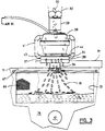
- a batch fry cooker 10 equipped to perform the process of the present invention is shown in the drawings and referring particularly to Figures 1 and 2, comprises a sheet metal housing 11 supported on legs 12 and including a generally rectangular vat 13 for containing a body of cooking oil 14.
- An insulated firebox 16 is arranged in a lower portion of the housing 11 and is provided with a gas burner 17 serving to furnish heat to the vat 13 for raising the temperature of the cooking oil 14.
- a stack or chimney 18 communicates with the firebox 16 and carries the products of combustion outside of the processing plant. Suitable couplings (not shown) are provided to the cooking vat or pan so that oil may be introduced or removed from the vat.
- Suitable temperature sensors 15 are provided coupled to the gas burner 17 through a control logic system so that when the oil temperature in the vat 13 should fall, say, after the introduction of a batch of potato slices 19, the gas burner 17 will be engaged to supply a greater quantity of heat to the vat so that the cooking may take place at higher cooking temperatures, if that be desired.
- a takeout conveyor 21 is operatively mounted in one end of the cooker 10 and arranged with a portion disposed below the level of the cooking oil 14 so that the conveyor may receive the cooked product thereupon for removal from the vat 13 at the end of a batch cooked cycle.
- the takeout conveyor 21 may be of conventional construction employing a wire mesh belt, as illustrated, and driven by a motor (not shown) so that the top rim of the conveyor belt may lift the product from the vat upwardly end onto another conveyor or other depository in the plant (not shown).
- the takeout conveyor 21 may be equipped to be raised such as by hydraulic cylinders 22 so that a thorough cleaning can be made of the cooker 10.
- a pivotal dam or gate 26 extends over the lower end of the takeout conveyor 21 as illustrated in Figures 1, 4-7 and serves to define in its lower condition, as shown in Figures 1, 4-6, one end of the cooking vat and prevent the potato slices from lodging upon the takeout conveyor.
- the dam or gate 26 extends laterally across the full width of the cooking vat 13 and is coupled to the hydraulic cylinder 27 through a chain or cable 28 so that the dam 26 may be shifted from a lowered position, as illustrated in Figure 1, to a raised position shown in Figure 7 for permitting a batch of cooked potato chips to be received upon the takeout conveyor for removal from the vat.
- the dam is suitably mounted at its upper ends to the housing 11 through a shaft and bearing assembly (not shown) well known in this art.
- a potato slicer 29 is operatively mounted on a spaced pair of rails 31 extending laterally of the cooker 10 and arranged so that the slicer 29 may be shifted from the position shown in full lines in Figure 2 to a second position as illustrated in broken lines, an out of the way position but one permitting the slicer to be employed for depositing potato slices in an adjacent cooker (not shown) so that the slicer 29 may serve two batch cookers in alternate fashion.
- the slicer 29 is mounted on a carriage which is movable on the rails 31 by a driving motor (not shown) so that the slicer may participate in the control logic sequence, illustrated in Figure 9, of being in place over the cooking vat 13 only when necessary for slicing potato products and thereafter may be moved to serve an adjacent cooker or placed in simply an out of the way position while cooking moves forward in the unit 10.
- a supply of potatoes is delivered to the inlet of the slicer 29, as illustrated in Figures 1 and 3, potatoes arriving in an auger 32 which deposits the potatoes one at a time into the receiver 33 of the slicer.
- the slicer 29 may be any of those commercially available in the field such as a Urschel slicer Model CC and adapted to slice potatoes at desired thicknesses for frying.
- the potatoes 30 may be sliced in batches on the order of 100 to 150 pounds, batches of 120 pounds being typical. Potatoes 30 issue from a discharge 34 of the slicer 29 as slices 36 in multiple rapid fashion which could be characterized as a flurry of slices 36. As shown in Figures 1 and 3, a discharge chute 37 is mounted below the slicer discharge 34 and extends outwardly and downwardly at a shallow angle from the rear of the slicer to terminate in a lip 38. The discharge chute is provided with upstanding sides 39 so as to confine the slices and to define a path for a blast of air which serves to sweep the slices 36 from the chute in airborne fashion out over the vat of cooking oil 14, as illustrated in Figures 1 and 3.
- an air blast manifold 41 is mounted on the slicer carriage and includes a venturi inspirator 42 coupled to the manifold and operative to receive a supply of compressed air on the order of 50 to 90 psi and to entrain a large volume of ambient air for discharge through a dispersion slot 43, or air from a blower at about 8 oz. pressure may be used as an alternate supply source for discharge through the dispersion slot 43 arranged in a manifold tube 44 disposed to define a rear portion of the slicer discharge chute 37, shown in Figure 3.
- Air is supplied to the manifold 41 as indicated in Figures 1-3 to exit the manifold 41 in a high velocity blast through the dispersion slot 43 so as to receive in the blast of air the slices descending from the slicer and to carry the slices airborne over the surface of the cooking oil where they may descend in free fall with a minimum of layering, preferably in a layer of one slice thickness in the oil. This has been found to substantially reduce the incidence of clumping upon introducing cold, uncooked potato slices into the body of hot cooking oil which was the problem of longstanding in this field.
- the slicer may be shifted to the out of the way position illustrated in Figure 2 in broken lines and it resides there during the remainder of the cooking cycle.
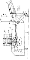
- a motor driven paddle and dunker mechanism 46 is provided on the batch cooker 10.
- the paddle and dunker mechanism 46 is arranged on a carriage 47 which is motor driven to traverse the cooking vat 13 and to straddle the cooker 10, as shown in Figures 1 and 2.
- the carriage is equipped with a wheel 48 at each of its four corners which rides on a track defined by the top flange on the housing 11.
- the paddle and dunker mechanism is equipped to move in accordance with a program sequence, shown in Figure 9, from an extreme left hand position as illustrated in Figure 4 to an extreme right hand position as illustrated in Figure 5 to achieve the desired chip mixing and dunking operation.
- the paddle and dunker operative components are mounted on the carriage 47 and are arranged for movement vertically from a position above the oil level as illustrated in Figures 1 and 7 to a lowered position where the paddle and dunker mechanism, may be active in the cooking oil for mixing and dunking, as illustrated in Figures 4-6.
- the paddle wheel and dunker mechanism is retracted from the oil during the slice loading operation as illustrated in Figure 1, and for the slice removal operation as illustrated in Figure 7, as indicated in the logic sequence of Figure 9.
- Two paddle wheels 51 are journalled at each of their ends to a yoke 52 which is mounted to the carriage 47 to be movable vertically along the upwardly extending guide rods 53 so that the paddle wheels and dunker mechanism may be raised and lowered with respect to the cooking oil 14.
- Each paddle wheel is equipped with an array of paddles 54 disposed at varying attack angles with respect to the cooking oil so as to create a somewhat turbulent flow pattern for agitation of the chips as the paddle wheels rotate.
- the paddle wheels 51 are driven by motor means (not shown) so as to rotate together either in the directions indicated by the arrows 56, 57 in the drawings.
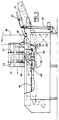
- a submerger or dunker mechanism 58 is arranged on the carriage 47 between the spaced apart paddle wheels 51 and is mounted and driven to reciprocate vertically as indicated by the arrow 59 over a stroke extending just above the oil level as indicated in Figure 5 to a lower position below the oil level as illustrated in Figures 4 and 6.
- the dunker 58 extends laterally the full width of the vat 13, as illustrated in Figure 2.
- Motor means 61 are arranged on the carriage 47 serving to reciprocate the dunker over about a four inch stroke at 30 strokes per minute.
- the paddle wheels 51 are motor driven to rotate at about 39 to 40 rpm in directions indicated by the arrows 56 and 57, Figures 5 and 6, as dictated by the program logic controller, Figure 9, and related to the direction of movement or travel of the carriage 47.
- the paddle and dunker mechanism to mix the batch of slices uniformly and continuously during the cook cycle by urging the chips which may be disposed, for example, on the right side of the vat as viewed in Figure 4 through the paddle array and beneath the dunker, as illustrated in Figure 6, to a position where the batch of slices is located as shown in Figure 5.
- the dunker or submerger 58 extends laterally the full width of the vat, each of the slices, more than likely, will be encountered by the dunker as the slices are moved from one end of the vat to the other.
- the paddle wheels rotate clockwise as indicated by arrows 56.
- the paddle wheels rotate counterclockwise as indicated by the arrows 57.
- the paddle wheels 51 continue to rotate for about five seconds in the same rotational direction even as the carriage changes direction. This is illustrated in Figures 4 and 5, where in Figure 5 the carriage has just begun moving towards the left but the paddle wheels continue the direction of rotation 56 undertaken when the carriage moved to the right as indicated in Figure 4. After the brief period of reverse direction of the carriage, the paddle wheels stop and are then rotated in the opposite direction 57 such as illustrated in Figure 6.
- a sweep conveyor 66 is arranged to gather the cooked chips and urge them towards the takeout conveyor 21 upon completion of the cooking period, Figure 7.
- the sweep conveyor extends laterally across the vat 13 and comprises a screen like mesh which drapes from a conveyor rod 67 which is equipped to be moved from one end of the vat 13 to the other.
- the conveyor curtain extends from the rod 67 to beneath the oil surface and preferably touches the bottom of the vat so that all cooked portions of the potato slices may be carried from the oil onto the takeout conveyor.
- the sweep conveyor 66 occupies a position, when not in use, at the end of the vat opposite the takeout conveyor so that the full length of the vat between the sweep conveyor 66 and pivotal dam 26 may be used as a cooking zone which is traversed by the paddle and dunker mechanism 46.
- the paddle and dunker mechanism 46 is raised from the lowered active position as illustrated in Figures 4-6 to the raised, out of the way, position as illustrated in Figures 1 and 7.
- a suitable programable logic controller for this invention is the Allen-Bradley SLC-150 programable logic controller available from the Allen-Bradley Company, 1201 South Second Street, Milwaukee, Wisconsin 53214.
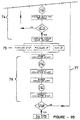
- the vat of cooking oil is prepared to a desired cooking temperature, for example, 305°F.
- a typical batch of potatoes can be selected, for example, a batch weighing approximately 120 pounds of peeled potatoes, representing Step 72.
- the potato slicer 29 is moved into position along the rails 31 to a mid-position over the cooking vat 13 and the air jet 42 is turned on so as to generate the blast of air through the dispersion slot 43. Potatoes are fed to the slicer through the auger 32 and it has bean found that it takes about 45 to 50 seconds to slice approximately 120 pounds of potatoes. The air jet scatters the slices uniformly over the surface of the cooking oil 14, minimizing the tendency towards clumping. Thus completes Step 73 in Figure 8.
- the potato slicer 29 is then moved along the rails 31 to an out of the way position as illustrated in Figure 2.
- the paddle and dunker mechanism 46 is lowered into the cooking oil from the position shown in Figure 1, to that illustrated in Figures 4 through 6, and the stirring rotation is begun while the carriage 47 moves back and forth at a rate of approximately six cycles a minute.
- the stirring and submerging operation, 74 moves the potato slices from one end of the cooking vat to the other as may be seen by comparing Figure 4 with Figure 5.
- the paddle wheels 51 rotate clockwise to the end portion of the vat and continue clockwise rotation for about two seconds of the return left movement.
- the paddles then stop and reverse rotation to counterclockwise.
- the carriage reaches the end of the left stroke, it starts back to the right and the paddles continue counterclockwise for about two seconds and then stop and reverse to clockwise rotation. This cycle is repeated each time.
- the stirring and dunking action continues in the cooking process for about 7 to 9 minutes or until the oil temperature is returned to about 280°F. by actuation of the gas burner 17 or other heat source.
- the program controller stops the stirring action and the carriage is elevated so as to remove the paddle and dunker mechanism to the raised position as indicated in Figure 7.
- the dam or gate 26 is pivoted clockwise from a lowered position as indicated in Figure 6 to the raised position as indicated in Figure 7, thus preparing the vat for removal of the cooked slices: Step 75 in Figure 8.
- the sweep conveyor 66 is then advanced across the length of the cooking vat to gather together the potato slices or cooked chips and move the chips to the takeout conveyor 21.
- the conveyor drive mechanism is started to elevate the chips from the cooker, permitting the oil to drain from the chips, and for further handling: Step 76 of Figure 8.
- the swinging dam or gate 26 When the cooking vat is cleared of chips, the swinging dam or gate 26 is lowered into the position as shown in Figure 1 and the sweep conveyor is retracted to the other end of the vat 13.
- the gas burner 17 may continue to fire so as to return the oil temperature to the starting point of about 305°F.:Step 77, Figure 8.
- the total time of the cook cycle averages about nine and a half to ten minutes. Changing temperature conditions, potato batch sizes, potato slice thickness and solid contents will change the cycle time and chip texture, however, all the stirring mechanism action will remain the same.
- a programable logic controller such as the Allen-Bradley SLC-150 connected to suitable limit switches and temperature sensors 15.
Landscapes
- Engineering & Computer Science (AREA)
- Food Science & Technology (AREA)
- Chemical & Material Sciences (AREA)
- Oil, Petroleum & Natural Gas (AREA)
- General Preparation And Processing Of Foods (AREA)
- Preparation Of Fruits And Vegetables (AREA)
- Frying-Pans Or Fryers (AREA)
- Cookers (AREA)
Applications Claiming Priority (1)
| Application Number | Priority Date | Filing Date | Title |
|---|---|---|---|
| US07/297,415 US4977821A (en) | 1989-01-13 | 1989-01-13 | Automatic stirring of batch fried food products |
Publications (2)
| Publication Number | Publication Date |
|---|---|
| EP0484598A1 true EP0484598A1 (de) | 1992-05-13 |
| EP0484598B1 EP0484598B1 (de) | 1993-08-04 |
Family
ID=23146220
Family Applications (1)
| Application Number | Title | Priority Date | Filing Date |
|---|---|---|---|
| EP90312176A Expired - Lifetime EP0484598B1 (de) | 1989-01-13 | 1990-11-07 | Ein diskontinuierliches Verfahren und Kocher für fritierte Nahrungsmittelprodukte |
Country Status (7)
| Country | Link |
|---|---|
| US (1) | US4977821A (de) |
| EP (1) | EP0484598B1 (de) |
| AT (1) | ATE92275T1 (de) |
| AU (1) | AU627414B2 (de) |
| DE (1) | DE69002630T2 (de) |
| DK (1) | DK0484598T3 (de) |
| ES (1) | ES2042221T3 (de) |
Families Citing this family (12)
| Publication number | Priority date | Publication date | Assignee | Title |
|---|---|---|---|---|
| US5193442A (en) * | 1991-01-16 | 1993-03-16 | Anheuser-Busch Companies, Inc. | Use of fluid to agitate articles |
| US5580598A (en) * | 1995-11-03 | 1996-12-03 | Heat And Control. Inc. | Multi-product food cooking system |
| CN1166307C (zh) * | 2000-02-07 | 2004-09-15 | 瑞科特公司 | 用于制作可堆叠的休闲食品薄片的设备和方法 |
| US20040161515A1 (en) * | 2003-02-19 | 2004-08-19 | Ed Pilla | Method and apparatus for producing and selling potato chips |
| US20070087110A1 (en) * | 2003-02-19 | 2007-04-19 | Edward Pilla | Method and apparatus for making long-sliced potato chips |
| US7303777B2 (en) * | 2004-07-20 | 2007-12-04 | Frito-Lay North America, Inc. | Method for continuously making kettle style potato chips |
| KR100796322B1 (ko) | 2006-12-06 | 2008-01-21 | 이은관 | 튀김옷 도포장치 |
| US8808779B2 (en) * | 2007-07-13 | 2014-08-19 | Frito-Lay North America, Inc. | Method for reducing the oil content of potato chips |
| US20160058243A1 (en) * | 2008-07-22 | 2016-03-03 | Heat And Control, Inc. | Universal potato chip cooker |
| GB2481468B (en) * | 2011-01-31 | 2012-06-20 | Frito Lay Trading Co Gmbh | Apparatus and method in the manufacture of low oil potato chips |
| CN103947699B (zh) * | 2014-05-12 | 2016-01-20 | 新昌县羽林街道达康机械厂 | 一种全自动快捷薯片油炸机 |
| US20160235110A1 (en) * | 2015-02-17 | 2016-08-18 | Frito-Lay North America, Inc. | Method and apparatus for controlling the flow of product over a product attrition bed |
Citations (3)
| Publication number | Priority date | Publication date | Assignee | Title |
|---|---|---|---|---|
| EP0260029A2 (de) * | 1986-08-27 | 1988-03-16 | Mike-Sell's Potato Chip Co. | Verfahren und Vorrichtung zur Herstellung eines Kartoffelnahrungsmittels |
| US4844930A (en) * | 1987-07-22 | 1989-07-04 | Borden, Inc. | Method for making potato chips |
| US4863750A (en) * | 1986-05-07 | 1989-09-05 | Frito-Lay, Inc. | Method for making potato chips having batch-fried texture and flavor |
Family Cites Families (3)
| Publication number | Priority date | Publication date | Assignee | Title |
|---|---|---|---|---|
| US2886439A (en) * | 1958-03-18 | 1959-05-12 | Frito Company | Method for producing potato chips |
| US3218959A (en) * | 1963-12-26 | 1965-11-23 | John D Swisher | Machine for making potato chips |
| US4706556A (en) * | 1986-01-13 | 1987-11-17 | Vanmark Corporation | Potato chip manufacturing machine |
-
1989
- 1989-01-13 US US07/297,415 patent/US4977821A/en not_active Expired - Fee Related
-
1990
- 1990-11-07 DK DK90312176.2T patent/DK0484598T3/da active
- 1990-11-07 DE DE90312176T patent/DE69002630T2/de not_active Expired - Fee Related
- 1990-11-07 AT AT90312176T patent/ATE92275T1/de active
- 1990-11-07 ES ES199090312176T patent/ES2042221T3/es not_active Expired - Lifetime
- 1990-11-07 EP EP90312176A patent/EP0484598B1/de not_active Expired - Lifetime
- 1990-11-16 AU AU66667/90A patent/AU627414B2/en not_active Ceased
Patent Citations (3)
| Publication number | Priority date | Publication date | Assignee | Title |
|---|---|---|---|---|
| US4863750A (en) * | 1986-05-07 | 1989-09-05 | Frito-Lay, Inc. | Method for making potato chips having batch-fried texture and flavor |
| EP0260029A2 (de) * | 1986-08-27 | 1988-03-16 | Mike-Sell's Potato Chip Co. | Verfahren und Vorrichtung zur Herstellung eines Kartoffelnahrungsmittels |
| US4844930A (en) * | 1987-07-22 | 1989-07-04 | Borden, Inc. | Method for making potato chips |
Also Published As
| Publication number | Publication date |
|---|---|
| DE69002630T2 (de) | 1993-11-11 |
| AU6666790A (en) | 1992-06-11 |
| US4977821A (en) | 1990-12-18 |
| EP0484598B1 (de) | 1993-08-04 |
| ES2042221T3 (es) | 1993-12-01 |
| DK0484598T3 (da) | 1993-10-18 |
| ATE92275T1 (de) | 1993-08-15 |
| AU627414B2 (en) | 1992-08-20 |
| DE69002630D1 (de) | 1993-09-09 |
Similar Documents
| Publication | Publication Date | Title |
|---|---|---|
| US5112633A (en) | Automatic stirring of batch fried food products | |
| EP0484598B1 (de) | Ein diskontinuierliches Verfahren und Kocher für fritierte Nahrungsmittelprodukte | |
| US3908531A (en) | Automatic french fryer | |
| US4700617A (en) | Automatic frying machine | |
| EP1225808B1 (de) | Kontinuierlicher misch- oder ruehrfrittierkocher | |
| WO2003101262A1 (fr) | Appareil de cuisson automatique d'aliments | |
| JP2000217720A (ja) | パン粉付き食品用フライ料理器具 | |
| CN1781414B (zh) | 一种智能化的滑炒烹调方法 | |
| US5259302A (en) | Automatic deep fry apparatus | |
| CN110050948A (zh) | 一种面类食品即时制作方法及其全自动设备 | |
| JP3049084B2 (ja) | バッチフライド食品の調理方法及び装置 | |
| GB2161294A (en) | Process and apparatus for preparing fried sausage products | |
| AU744175B2 (en) | Process and corresponding machines for the preparation of ready-cooked and semi-cooked dishes | |
| CA2029919A1 (en) | Automatic stirring of batch fried food products | |
| CN210094575U (zh) | 一种面类食品即时制作的全自动设备 | |
| US2056845A (en) | Food handling and preparing apparatus | |
| KR102591780B1 (ko) | 식품 제조장치 | |
| JP4614117B2 (ja) | 釜内攪拌装置 | |
| JPH0238206B2 (ja) | Aburasanpushikichoriki | |
| KR102556331B1 (ko) | 식품 제조장치 | |
| KR102555222B1 (ko) | 식품 제조장치 | |
| KR102555221B1 (ko) | 식품 제조장치 | |
| KR20220106513A (ko) | 식품 제조장치 | |
| CN220898565U (zh) | 一种具有自动上料功能的新型自动旋转炒锅 | |
| JPH069468B2 (ja) | 揚げ煎餅の製造装置 |
Legal Events
| Date | Code | Title | Description |
|---|---|---|---|
| PUAI | Public reference made under article 153(3) epc to a published international application that has entered the european phase |
Free format text: ORIGINAL CODE: 0009012 |
|
| 17P | Request for examination filed |
Effective date: 19911007 |
|
| AK | Designated contracting states |
Kind code of ref document: A1 Designated state(s): AT BE CH DE DK ES FR GB GR IT LI LU NL SE |
|
| 17Q | First examination report despatched |
Effective date: 19920612 |
|
| GRAA | (expected) grant |
Free format text: ORIGINAL CODE: 0009210 |
|
| AK | Designated contracting states |
Kind code of ref document: B1 Designated state(s): AT BE CH DE DK ES FR GB GR IT LI LU NL SE |
|
| REF | Corresponds to: |
Ref document number: 92275 Country of ref document: AT Date of ref document: 19930815 Kind code of ref document: T |
|
| REF | Corresponds to: |
Ref document number: 69002630 Country of ref document: DE Date of ref document: 19930909 |
|
| REG | Reference to a national code |
Ref country code: DK Ref legal event code: T3 |
|
| ITF | It: translation for a ep patent filed | ||
| ET | Fr: translation filed | ||
| REG | Reference to a national code |
Ref country code: ES Ref legal event code: FG2A Ref document number: 2042221 Country of ref document: ES Kind code of ref document: T3 |
|
| EPTA | Lu: last paid annual fee | ||
| REG | Reference to a national code |
Ref country code: GR Ref legal event code: FG4A Free format text: 3009375 |
|
| PLBE | No opposition filed within time limit |
Free format text: ORIGINAL CODE: 0009261 |
|
| STAA | Information on the status of an ep patent application or granted ep patent |
Free format text: STATUS: NO OPPOSITION FILED WITHIN TIME LIMIT |
|
| 26N | No opposition filed | ||
| PGFP | Annual fee paid to national office [announced via postgrant information from national office to epo] |
Ref country code: LU Payment date: 19941001 Year of fee payment: 5 |
|
| PGFP | Annual fee paid to national office [announced via postgrant information from national office to epo] |
Ref country code: FR Payment date: 19941013 Year of fee payment: 5 Ref country code: CH Payment date: 19941013 Year of fee payment: 5 |
|
| PGFP | Annual fee paid to national office [announced via postgrant information from national office to epo] |
Ref country code: SE Payment date: 19941014 Year of fee payment: 5 |
|
| PGFP | Annual fee paid to national office [announced via postgrant information from national office to epo] |
Ref country code: DK Payment date: 19941017 Year of fee payment: 5 Ref country code: AT Payment date: 19941017 Year of fee payment: 5 |
|
| PGFP | Annual fee paid to national office [announced via postgrant information from national office to epo] |
Ref country code: GB Payment date: 19941026 Year of fee payment: 5 Ref country code: DE Payment date: 19941026 Year of fee payment: 5 |
|
| PGFP | Annual fee paid to national office [announced via postgrant information from national office to epo] |
Ref country code: BE Payment date: 19941027 Year of fee payment: 5 |
|
| PGFP | Annual fee paid to national office [announced via postgrant information from national office to epo] |
Ref country code: ES Payment date: 19941110 Year of fee payment: 5 |
|
| PGFP | Annual fee paid to national office [announced via postgrant information from national office to epo] |
Ref country code: GR Payment date: 19941116 Year of fee payment: 5 |
|
| PGFP | Annual fee paid to national office [announced via postgrant information from national office to epo] |
Ref country code: NL Payment date: 19941130 Year of fee payment: 5 |
|
| EAL | Se: european patent in force in sweden |
Ref document number: 90312176.2 |
|
| PG25 | Lapsed in a contracting state [announced via postgrant information from national office to epo] |
Ref country code: LU Free format text: LAPSE BECAUSE OF NON-PAYMENT OF DUE FEES Effective date: 19951107 Ref country code: GB Effective date: 19951107 Ref country code: DK Effective date: 19951107 Ref country code: AT Effective date: 19951107 |
|
| REG | Reference to a national code |
Ref country code: DK Ref legal event code: EBP |
|
| PG25 | Lapsed in a contracting state [announced via postgrant information from national office to epo] |
Ref country code: SE Effective date: 19951108 Ref country code: ES Free format text: LAPSE BECAUSE OF THE APPLICANT RENOUNCES Effective date: 19951108 |
|
| PG25 | Lapsed in a contracting state [announced via postgrant information from national office to epo] |
Ref country code: LI Effective date: 19951130 Ref country code: CH Effective date: 19951130 Ref country code: BE Effective date: 19951130 |
|
| BERE | Be: lapsed |
Owner name: HEAT AND CONTROL INC. Effective date: 19951130 |
|
| PG25 | Lapsed in a contracting state [announced via postgrant information from national office to epo] |
Ref country code: GR Free format text: THE PATENT HAS BEEN ANNULLED BY A DECISION OF A NATIONAL AUTHORITY Effective date: 19960531 |
|
| PG25 | Lapsed in a contracting state [announced via postgrant information from national office to epo] |
Ref country code: NL Effective date: 19960601 |
|
| GBPC | Gb: european patent ceased through non-payment of renewal fee |
Effective date: 19951107 |
|
| REG | Reference to a national code |
Ref country code: CH Ref legal event code: PL |
|
| PG25 | Lapsed in a contracting state [announced via postgrant information from national office to epo] |
Ref country code: FR Effective date: 19960731 |
|
| REG | Reference to a national code |
Ref country code: GR Ref legal event code: MM2A Free format text: 3009375 |
|
| NLV4 | Nl: lapsed or anulled due to non-payment of the annual fee |
Effective date: 19960601 |
|
| PG25 | Lapsed in a contracting state [announced via postgrant information from national office to epo] |
Ref country code: DE Effective date: 19960801 |
|
| EUG | Se: european patent has lapsed |
Ref document number: 90312176.2 |
|
| REG | Reference to a national code |
Ref country code: FR Ref legal event code: ST |
|
| REG | Reference to a national code |
Ref country code: ES Ref legal event code: FD2A Effective date: 20010402 |
|
| PG25 | Lapsed in a contracting state [announced via postgrant information from national office to epo] |
Ref country code: IT Free format text: LAPSE BECAUSE OF NON-PAYMENT OF DUE FEES Effective date: 20051107 |