EP0485359A2 - Appareil d'inversion du champ magnétique externe pour appareil à disque magnéto-optique - Google Patents
Appareil d'inversion du champ magnétique externe pour appareil à disque magnéto-optique Download PDFInfo
- Publication number
- EP0485359A2 EP0485359A2 EP92100047A EP92100047A EP0485359A2 EP 0485359 A2 EP0485359 A2 EP 0485359A2 EP 92100047 A EP92100047 A EP 92100047A EP 92100047 A EP92100047 A EP 92100047A EP 0485359 A2 EP0485359 A2 EP 0485359A2
- Authority
- EP
- European Patent Office
- Prior art keywords
- permanent magnet
- magnetic field
- winding
- magneto
- rotary shaft
- Prior art date
- Legal status (The legal status is an assumption and is not a legal conclusion. Google has not performed a legal analysis and makes no representation as to the accuracy of the status listed.)
- Granted
Links
Images

Classifications
-
- G—PHYSICS
- G11—INFORMATION STORAGE
- G11B—INFORMATION STORAGE BASED ON RELATIVE MOVEMENT BETWEEN RECORD CARRIER AND TRANSDUCER
- G11B5/00—Recording by magnetisation or demagnetisation of a record carrier; Reproducing by magnetic means; Record carriers therefor
- G11B5/02—Recording, reproducing, or erasing methods; Read, write or erase circuits therefor
-
- G—PHYSICS
- G11—INFORMATION STORAGE
- G11B—INFORMATION STORAGE BASED ON RELATIVE MOVEMENT BETWEEN RECORD CARRIER AND TRANSDUCER
- G11B11/00—Recording on or reproducing from the same record carrier wherein for these two operations the methods are covered by different main groups of groups G11B3/00 - G11B7/00 or by different subgroups of group G11B9/00; Record carriers therefor
- G11B11/10—Recording on or reproducing from the same record carrier wherein for these two operations the methods are covered by different main groups of groups G11B3/00 - G11B7/00 or by different subgroups of group G11B9/00; Record carriers therefor using recording by magnetic means or other means for magnetisation or demagnetisation of a record carrier, e.g. light induced spin magnetisation; Demagnetisation by thermal or stress means in the presence or not of an orienting magnetic field
- G11B11/105—Recording on or reproducing from the same record carrier wherein for these two operations the methods are covered by different main groups of groups G11B3/00 - G11B7/00 or by different subgroups of group G11B9/00; Record carriers therefor using recording by magnetic means or other means for magnetisation or demagnetisation of a record carrier, e.g. light induced spin magnetisation; Demagnetisation by thermal or stress means in the presence or not of an orienting magnetic field using a beam of light or a magnetic field for recording by change of magnetisation and a beam of light for reproducing, i.e. magneto-optical, e.g. light-induced thermomagnetic recording, spin magnetisation recording, Kerr or Faraday effect reproducing
- G11B11/1055—Disposition or mounting of transducers relative to record carriers
- G11B11/10556—Disposition or mounting of transducers relative to record carriers with provision for moving or switching or masking the transducers in or out of their operative position
- G11B11/1056—Switching or mechanically reversing the magnetic field generator
Definitions
- the present invention relates to an external magnetic field inverting apparatus for a magneto-optical disc apparatus having the features according of the preamble of claim 1.
- a magneto-optical recording- and -reproducing device is known (GB-A-20 83 677), operating on a recording disc which comprises a substrate having magnetic thin films formed thereon.
- the magnetic easy directions of the films are perpendicular to the plane of the substrate, both films being magnetized in the same direction.
- An optical converging lens and a rotatable permanent magnet which is movable parallel to the plane of the recording disk are disposed on the opposite sides of the disk.
- reference numeral 1 designates a magneto-optical disc. Before a data is recorded on the magneto-optical disc, it is magnetized uniformly in the same direction (downward direction), as, for example, shown in the figures.
- An optical pickup apparatus 2 is located in opposing relation to one surface of the disc 1 to record the data on the disc surface and to reproduce the data therefrom. It is known that the optical pickup apparatus 2 utilizes a laser (semiconductor laser and the like) to record and to reproduce the data. The laser is converged by an objective lens 3 on the disc surface as an optical path 3a.
- An electromagnet 5 as the external magnetic field forming means is located at the disc surface opposite to the optical pickup apparatus 2 in facing relation to the optical pickup apparatus 2. This electromagnet 5 generates an external magnetic field H vertical to the disc surface as shown in the figures.
- the optical pickup apparatus 2 When the optical pickup apparatus 2 is moved to a predetermined disc surface and irradiates a laser thereon so that the disc surface is heated to a temperature (for example, 400°C) higher than Curie temperature, the magnetic domains in the heated portion become irregular. Under this condition, when a predetermined current is flowed to the electromagnet 5 such that an external magnetic field H (Fig. 2) opposite to the external magnetic field H shown in Fig. 1 is applied to the disc, the magnetization direction of the heated portion within the disc 1 becomes the same direction as that of the external magnetic field H as indicated by a broken line. Accordingly, under this condition, if the irradiation of the laser is stopped, the internal magnetic field is kept as shown by the broken line.
- a predetermined current is flowed to the electromagnet 5 such that an external magnetic field H (Fig. 2) opposite to the external magnetic field H shown in Fig. 1 is applied to the disc
- the magnetization direction of the heated portion within the disc 1 becomes the same direction as that of the external magnetic field
- the external magnetic field forming means is not limited to the electromagnet but can use a permanent magnet.
- Fig. 3 is a diagram shoving an example of an external magnetic field inverting apparatus 10 which uses a permanent magnet 5 as the external magnetic field forming means.
- the flat rectangular solid-shaped permanent magnet 5 that is magnetized with the illustrated polarities is located in opposing relation to the disc 1 and rotatably mounted to the apparatus. Its rotary shaft 6 is coupled to the rotary shaft of a stepping motor 7 through coupling means 8.
- the motor 7 is controlled on the basis of a drive signal from a system controller (not shown) and the permanent magnet 5 is half-rotated on the basis of the rotation of the motor 7.
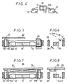
- the half-rotated condition of the permanent magnet is detected by a pair of switches 11 and 12 shown in Fig. 4.
- a projected member 13A is attached to a holder 13 which incorporates the permanent magnet 5 and the pair of switches 11 and 12 are located respectively at the positions to which the permanent magnet 5 is rotated by 180°. Then, the supply of the drive signal to the motor 7 is stopped by a signal obtained when the projected member 13A contacts with the switches 11 and 12. Thus, the half-rotated condition of the permanent magnet 5 can be stabilized.
- the external magnetic field inverting apparatus 10 employs the stepping motor 7 as a drive source for inverting the permanent magnet 5, it requires, in addition to the motor 7, circuits such as a driver and so on. This increases the manufacturing cost of the apparatus on the whole. Further, since the apparatus is constructed by using parts for consumption such as the motor 7, the pair of switches 11, 12 and so on, the apparatus is short in life span, poor in reliability and can not be miniaturized because of attaching the motor 7 and the like.
- the repulsive forces generated between the magnetic fields resulting from supplying the current to the winding and the magnetic field of the permanent magnet itself are different at the center of the rotation of the permanent magnet, it is possible to rotate the permanent magnet in the desired direction (clockwise direction or counter-clockwise direction) by the difference of the repulsive forces. If the winding remaines as is conducted, the permanent magnet is stabilized under the half-rotated state. The reason for this is that the magnetic field of the permanent magnet and the magnetic field of the winding become same in direction, and hence the repulsive force applied to the permanent magnet disappears.
- the magnetic field of the permanent magnet is utilized positively and only the magnetic field is generated from the winding at a necessary time, it is possible to freely alter the opposing polarity of the permanent magnet relative to the disc surface.
- the apparatus in which the rotation force given to the permanent magnet is formed by the magnetic field of the permanent magnet and the magnetic field of the winding, the apparatus can be miniaturized in size and the apparatus can be made high in reliability.
- a permanent magnet 15 constructed to have the center Lm thereof coincident with the axis of the rotary shaft 22 or the permanent magnet 15 .
- a positional relationship therebetween is selected such that both the centers Lc and Lm become coincident and a substantially C-shaped magnetic conductive member, for example, an iron member 30 is fixed to the side of the bearing portion of one rotary shaft 22 with the inclination of a predetermined angle ⁇ relative to the axis.
- this iron member 30 there is formed such a magnetic path that the magnetic flux of the winding 25 passes through the iron member 30 so that the magnetic field Hc of the winding is inclined by the angle ⁇ relative to the magnetic filed Hm of the permanent magnet 15.
- the rotation force for the permanent magnet 15 is generated by the composed magnetic field and hence, the permanent magnet 15 is rotated in the predetermined direction similarly as described above.
- the iron member 30 shown in Fig. 5 is exchanged with a short-circuit winding 33.
- the permanent magnet 15 is located along the center Lc of the winding 25 and the short-circuit winding 33 is located in opposing relation to one surface of the permanent magnet 15.
- the short-circuit winding is located with a predetermined distance from the permanent magnet 15 at the upper surface side of the permanent magnet 15 and at the left of the rotary shaft 22 of the permanent magnet.
- the magnetic flux from the winding 25 partially crosses the short-circuit winding 33 so that an electromotive force is induced therein. Then, on the basis of this electromotive force, a predetermined magnetic field is generated from the short-circuit winding 33.
- the composed magnetic field of this magnetic field and the magnetic field of the winding 25 is inclined by a predetermined angle, for example, ⁇ . As a result, the same rotation force as shown in Fig. 5 is applied to the permanent magnet 15 and the permanent magnet 15 can be rotated.
- the length of the permanent magnet 15 is selected to be substantially equal to the length of the track number that can be recorded on a disc.
- the optical pickup apparatus is moved to the corresponding track. This is only one example.
- magnetic field inversion detecting means for example, Hall element is attached to the main attaching plate 23 opposing to the permanent magnet 15 in facing relation to an elongated opening as shown in Fig.9 of the afore mentioned EP-Application. Since the polarity and the detection level of the detection output from this Hall element are changed dependent on the fact that the polarity of the permanent magnet 15 opposing to the Hall element is the N pole or S pole and also whether or not the external magnetic field Hm passes perpendicularly the Hall element from the permanent magnet 15, by this detection output, it is possible to check whether or not the permanent magnet 15 is inverted correctly and to detect the polarity thereof.
- the detection output is supplied to a system controller and the irradiation condition of the laser is controlled on the detection output therefrom.
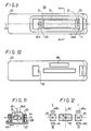
- FIG. 9 and the following drawings illustrate a third embodiment. Also in the third embodiment, like parts corresponding to those of Figs. 5 to 8 are marked with the same references. In this embodiment, however, the winding 25 is wound around a bobbin 40.
- a magnetic member 46 is located within a third quadrant III defined by a central axis 42 (X axis) of the winding 25 and an axis 44 (Y axis) perpendicular to the above mentioned central axis in the plane vertical to the rotation center Lm of the magnet 15. This magnetic member 46 is attached to the under surface of the frame 23 to be extended in the extension direction of the magnet 15.
- the magnet 15 when the winding 25 is not conducted, the magnet 15 is inclined as shown by a dotted line in Fig. 11, while when the winding 25 is conducted, the axis Lm of the magnet 15 is brought to the position coincident with the central axis 42 as shown by a solid line. If the flowing direction of the current is altered, this magnet 15 is inverted at the position shown by the solid line.
- the magnetic member 46 is located within the third quadrant, it is possible to locate it within a first quadrant I as shown by reference numeral 46a or within a second quadrant II as shown by reference numeral 46b in Fig. 12. In this case, the magnetic member can be attached on the bobbin 40. It is needless to say that the magnetic member may be located within a fourth quadrant IV as shown by reference numeral 46c.
- the magnetic members may be located within the quadrants symmetrical to each other with respect to the rotation axis Lm, that is, within the first quadrant I and the third quadrant III or the second quadrant II and the fourth quadrant IV, respectively.
- the external magnetic field inverting apparatus for magneto-optical disc apparatus inverts the permanent magnet by the magnetic field generated from the electromagnet winding so that this invention is suitable for use with a magneto-optical recording and reproducing apparatus such as a disc memory and the like.
Applications Claiming Priority (5)
| Application Number | Priority Date | Filing Date | Title |
|---|---|---|---|
| JP91992/85 | 1985-04-29 | ||
| JP60091992A JPS61250801A (ja) | 1985-04-29 | 1985-04-29 | 光磁気デイスク装置用外部磁界反転装置 |
| JP26038785A JPH06101082B2 (ja) | 1985-11-20 | 1985-11-20 | 光磁気デイスク装置用外部磁界反転装置 |
| JP260387/85 | 1985-11-20 | ||
| EP86902518A EP0222916B1 (fr) | 1985-04-29 | 1986-04-28 | Appareil d'inversion du champ mnagnetique externe pour disques photomagnetiques |
Related Parent Applications (2)
| Application Number | Title | Priority Date | Filing Date |
|---|---|---|---|
| EP86902518A Division EP0222916B1 (fr) | 1985-04-29 | 1986-04-28 | Appareil d'inversion du champ mnagnetique externe pour disques photomagnetiques |
| EP86902518.9 Division | 1986-04-28 |
Publications (3)
| Publication Number | Publication Date |
|---|---|
| EP0485359A2 true EP0485359A2 (fr) | 1992-05-13 |
| EP0485359A3 EP0485359A3 (en) | 1994-06-22 |
| EP0485359B1 EP0485359B1 (fr) | 1998-06-17 |
Family
ID=26433420
Family Applications (2)
| Application Number | Title | Priority Date | Filing Date |
|---|---|---|---|
| EP92100047A Expired - Lifetime EP0485359B1 (fr) | 1985-04-29 | 1986-04-28 | Appareil d'inversion du champ magnétique externe pour appareil à disque magnéto-optique |
| EP86902518A Expired - Lifetime EP0222916B1 (fr) | 1985-04-29 | 1986-04-28 | Appareil d'inversion du champ mnagnetique externe pour disques photomagnetiques |
Family Applications After (1)
| Application Number | Title | Priority Date | Filing Date |
|---|---|---|---|
| EP86902518A Expired - Lifetime EP0222916B1 (fr) | 1985-04-29 | 1986-04-28 | Appareil d'inversion du champ mnagnetique externe pour disques photomagnetiques |
Country Status (5)
| Country | Link |
|---|---|
| US (1) | US4748606A (fr) |
| EP (2) | EP0485359B1 (fr) |
| KR (1) | KR940005552B1 (fr) |
| DE (1) | DE3650686T2 (fr) |
| WO (1) | WO1986006534A1 (fr) |
Families Citing this family (28)
| Publication number | Priority date | Publication date | Assignee | Title |
|---|---|---|---|---|
| JP2566924B2 (ja) * | 1986-07-14 | 1996-12-25 | キヤノン株式会社 | 光磁気記録装置 |
| JPH0727606B2 (ja) * | 1986-12-11 | 1995-03-29 | ソニー株式会社 | 記録型光デイスクに対する磁界印加装置 |
| US4813007A (en) * | 1987-02-13 | 1989-03-14 | Oki Electric Industry Co., Ltd. | External magnetic field generating device |
| JP2682621B2 (ja) * | 1987-03-03 | 1997-11-26 | オリンパス光学工業株式会社 | バイアス磁界異常検出装置 |
| JPH0661122B2 (ja) * | 1987-05-08 | 1994-08-10 | シャープ株式会社 | 光磁気ディスク装置 |
| US4928192A (en) * | 1987-12-23 | 1990-05-22 | Konica Corporation | Process for identifying disks and automatically configuring a disk drive system |
| JP2647877B2 (ja) * | 1987-12-26 | 1997-08-27 | シャープ株式会社 | 光磁気カード記録再生装置 |
| US5022017A (en) * | 1988-04-29 | 1991-06-04 | Laser Magnetic Storage International Company | Magneto optic data recording system with variable field strength, actuator therefor and method of providing |
| US5111440A (en) * | 1988-04-29 | 1992-05-05 | North American Philips Corporation | An apparatus for controlling the rotation and stabilizing the position of a magnet device |
| US4962492A (en) * | 1988-04-29 | 1990-10-09 | Laser Magnetic Storage International Company | Magneto-optic data recording system, actuating device therefor and method of providing same |
| JPH0272402U (fr) * | 1988-11-16 | 1990-06-01 | ||
| JPH0636481Y2 (ja) * | 1989-02-13 | 1994-09-21 | ティアツク株式会社 | 光磁気ディスク装置のバイアス磁界印加装置 |
| US5159584A (en) * | 1989-08-15 | 1992-10-27 | Olympus Optical Company Limited | Bias-Magnetic field generating system of photo-magnetic recording device |
| DE3927903A1 (de) * | 1989-08-24 | 1991-02-28 | Thomson Brandt Gmbh | Haltevorrichtung fuer eine platte in einem magneto-optischen aufzeichnungs- und/oder wiedergabegeraet |
| JPH03120601A (ja) * | 1989-10-04 | 1991-05-22 | Nikon Corp | 光磁気ディスク装置の外部磁界発生装置 |
| DE69018207T2 (de) * | 1989-12-06 | 1995-07-27 | Matsushita Electric Ind Co Ltd | Magnetisches Vorspanngerät für ein magnetooptisches Platten-Antriebsgerät. |
| US5351221A (en) * | 1989-12-08 | 1994-09-27 | Ricoh Company, Ltd. | Apparatus for applying bias magnetic field including a rotatable magnet and a plurality of coils for controlling the rotation of the magnet |
| US5229983A (en) * | 1989-12-28 | 1993-07-20 | Matsushita Electric Industrial Co., Ltd. | Bias magnetic field generating apparatus for magneto-optical recording and reproducing system |
| JP2791505B2 (ja) * | 1990-07-20 | 1998-08-27 | 三菱電機株式会社 | 光磁気ディスク装置におけるバイアス磁界印加装置 |
| JPH04232602A (ja) * | 1990-09-21 | 1992-08-20 | Sundstrand Data Control Inc | 磁気光ディスク駆動装置の気密封止された磁気バイアス装置 |
| JPH05303790A (ja) * | 1992-04-24 | 1993-11-16 | Sony Corp | 光磁気ディスク装置 |
| US5345431A (en) * | 1992-09-14 | 1994-09-06 | Hewlett-Packard Company | Write and erase assembly for magneto-optic drive apparatus |
| GB2293264B (en) * | 1994-09-01 | 1998-05-27 | Asahi Optical Co Ltd | Magneto-optical disk apparatus |
| WO1996011484A2 (fr) * | 1994-10-06 | 1996-04-18 | Philips Electronics N.V. | Actionneur a corps d'aimant rotatif; unite d'actionnement comprenant l'actionneur et un systeme de commande; dispositif magneto-optique comprenant l'actionneur et balayeur comprenant l'actionneur |
| GB9722938D0 (en) * | 1997-10-30 | 1998-01-07 | Flying Null Ltd | Generating magnetic fields |
| US20040248093A1 (en) * | 2000-11-27 | 2004-12-09 | Coombs James Howard | Magneto-optical bio-discs and systems including related methods |
| US20020172980A1 (en) * | 2000-11-27 | 2002-11-21 | Phan Brigitte Chau | Methods for decreasing non-specific binding of beads in dual bead assays including related optical biodiscs and disc drive systems |
| US20030003464A1 (en) * | 2000-11-27 | 2003-01-02 | Phan Brigitte C. | Dual bead assays including optical biodiscs and methods relating thereto |
Family Cites Families (7)
| Publication number | Priority date | Publication date | Assignee | Title |
|---|---|---|---|---|
| FR2249475B1 (fr) * | 1973-10-29 | 1980-11-07 | Motorola Inc | |
| GB2083677B (en) * | 1980-07-16 | 1985-01-23 | Matsushita Electric Industrial Co Ltd | Magnetooptical recording medium and a magnetooptical recording-and reeproducing device |
| JPS5724047A (en) * | 1980-07-21 | 1982-02-08 | Matsushita Electric Ind Co Ltd | Recorder and reproducer |
| JPS5938951A (ja) * | 1982-08-27 | 1984-03-03 | Matsushita Electric Ind Co Ltd | 光学磁気記録再生装置 |
| JPS5992406A (ja) * | 1982-11-17 | 1984-05-28 | Matsushita Electric Ind Co Ltd | 光磁気記録装置 |
| JPS59146408A (ja) * | 1983-02-09 | 1984-08-22 | Matsushita Electric Ind Co Ltd | 光磁気記録媒体用記録消去磁場印加装置 |
| US4701895A (en) * | 1986-03-28 | 1987-10-20 | Rca Corporation | Magnetic biasing apparatus for magneto-optic recording including a permanent magnet |
-
1986
- 1986-04-28 EP EP92100047A patent/EP0485359B1/fr not_active Expired - Lifetime
- 1986-04-28 KR KR1019860700953A patent/KR940005552B1/ko not_active Expired - Fee Related
- 1986-04-28 WO PCT/JP1986/000216 patent/WO1986006534A1/fr not_active Ceased
- 1986-04-28 DE DE3650686T patent/DE3650686T2/de not_active Expired - Fee Related
- 1986-04-28 EP EP86902518A patent/EP0222916B1/fr not_active Expired - Lifetime
- 1986-04-28 US US07/012,458 patent/US4748606A/en not_active Expired - Lifetime
Also Published As
| Publication number | Publication date |
|---|---|
| US4748606A (en) | 1988-05-31 |
| DE3650686D1 (de) | 1998-07-23 |
| EP0222916B1 (fr) | 1993-02-03 |
| KR940005552B1 (ko) | 1994-06-20 |
| DE3650686T2 (de) | 1998-10-22 |
| EP0485359B1 (fr) | 1998-06-17 |
| EP0222916A4 (fr) | 1989-06-13 |
| WO1986006534A1 (fr) | 1986-11-06 |
| KR880700389A (ko) | 1988-03-15 |
| EP0485359A3 (en) | 1994-06-22 |
| EP0222916A1 (fr) | 1987-05-27 |
Similar Documents
| Publication | Publication Date | Title |
|---|---|---|
| EP0485359B1 (fr) | Appareil d'inversion du champ magnétique externe pour appareil à disque magnéto-optique | |
| KR960000829B1 (ko) | 자기 광 기록에 사용되는 코일용 회전 제어 장치 | |
| JPS62185269A (ja) | 光磁気記録装置 | |
| US5563871A (en) | Rotary actuator with a magnetic bias bearing configuration for rotating an optical element in an optical data storage system | |
| US5243580A (en) | Head for a magneto-optical recording apparatus | |
| JPS63167402A (ja) | 情報記録再生装置 | |
| JP3070516B2 (ja) | 光ディスク装置 | |
| US5369628A (en) | Magneto-optic recording medium, magneto-optic recording system and magneto-optic recording method | |
| JPH0560162B2 (fr) | ||
| JPS628345A (ja) | 光学的情報記録再生装置 | |
| EP0431604B1 (fr) | Appareil de polarisation magnétique pour un appareil d'entraînement de disque magnéto-optique | |
| US5619479A (en) | Translational bias-field device for a magneto-optical system | |
| JP2706265B2 (ja) | 光学ヘッド装置 | |
| US5197048A (en) | Magneto-optic recording medium, magneto-optic recording system and magneto-optic recording method | |
| JPS6334757A (ja) | 光磁気デイスク装置 | |
| US5710747A (en) | Dual coil, translational bias-field device for a magneto-optical system | |
| JPH0553003B2 (fr) | ||
| JPH10208264A (ja) | 光ピックアップ装置 | |
| JPH0422403Y2 (fr) | ||
| JPS6258441A (ja) | 光磁気記録再生装置 | |
| JPS6337840A (ja) | 光磁気記録装置 | |
| JPH06101082B2 (ja) | 光磁気デイスク装置用外部磁界反転装置 | |
| JPH01179203A (ja) | バイアス磁界コイル駆動装置 | |
| JPH0325702A (ja) | 光磁気情報記録再生装置 | |
| JPH0319102A (ja) | 光磁気記録用バイアス磁界発生装置 |
Legal Events
| Date | Code | Title | Description |
|---|---|---|---|
| PUAI | Public reference made under article 153(3) epc to a published international application that has entered the european phase |
Free format text: ORIGINAL CODE: 0009012 |
|
| 17P | Request for examination filed |
Effective date: 19920102 |
|
| AC | Divisional application: reference to earlier application |
Ref document number: 222916 Country of ref document: EP |
|
| AK | Designated contracting states |
Kind code of ref document: A2 Designated state(s): DE FR GB |
|
| PUAL | Search report despatched |
Free format text: ORIGINAL CODE: 0009013 |
|
| AK | Designated contracting states |
Kind code of ref document: A3 Designated state(s): DE FR GB |
|
| 17Q | First examination report despatched |
Effective date: 19960820 |
|
| GRAG | Despatch of communication of intention to grant |
Free format text: ORIGINAL CODE: EPIDOS AGRA |
|
| GRAG | Despatch of communication of intention to grant |
Free format text: ORIGINAL CODE: EPIDOS AGRA |
|
| GRAG | Despatch of communication of intention to grant |
Free format text: ORIGINAL CODE: EPIDOS AGRA |
|
| GRAH | Despatch of communication of intention to grant a patent |
Free format text: ORIGINAL CODE: EPIDOS IGRA |
|
| GRAH | Despatch of communication of intention to grant a patent |
Free format text: ORIGINAL CODE: EPIDOS IGRA |
|
| GRAA | (expected) grant |
Free format text: ORIGINAL CODE: 0009210 |
|
| AC | Divisional application: reference to earlier application |
Ref document number: 222916 Country of ref document: EP |
|
| AK | Designated contracting states |
Kind code of ref document: B1 Designated state(s): DE FR GB |
|
| REF | Corresponds to: |
Ref document number: 3650686 Country of ref document: DE Date of ref document: 19980723 |
|
| ET | Fr: translation filed | ||
| PLBE | No opposition filed within time limit |
Free format text: ORIGINAL CODE: 0009261 |
|
| STAA | Information on the status of an ep patent application or granted ep patent |
Free format text: STATUS: NO OPPOSITION FILED WITHIN TIME LIMIT |
|
| 26N | No opposition filed | ||
| PGFP | Annual fee paid to national office [announced via postgrant information from national office to epo] |
Ref country code: DE Payment date: 20010423 Year of fee payment: 16 |
|
| REG | Reference to a national code |
Ref country code: GB Ref legal event code: IF02 |
|
| PGFP | Annual fee paid to national office [announced via postgrant information from national office to epo] |
Ref country code: FR Payment date: 20020410 Year of fee payment: 17 |
|
| PG25 | Lapsed in a contracting state [announced via postgrant information from national office to epo] |
Ref country code: DE Free format text: LAPSE BECAUSE OF NON-PAYMENT OF DUE FEES Effective date: 20021101 |
|
| PG25 | Lapsed in a contracting state [announced via postgrant information from national office to epo] |
Ref country code: FR Free format text: LAPSE BECAUSE OF NON-PAYMENT OF DUE FEES Effective date: 20031231 |
|
| REG | Reference to a national code |
Ref country code: FR Ref legal event code: ST |
|
| PGFP | Annual fee paid to national office [announced via postgrant information from national office to epo] |
Ref country code: GB Payment date: 20050427 Year of fee payment: 20 |
|
| PG25 | Lapsed in a contracting state [announced via postgrant information from national office to epo] |
Ref country code: GB Free format text: LAPSE BECAUSE OF EXPIRATION OF PROTECTION Effective date: 20060427 |
|
| REG | Reference to a national code |
Ref country code: GB Ref legal event code: PE20 |