EP0485767A1 - Verrouillage pour l'aile, en particulier l'aile coulissante d'une fenêtre, porte etc. - Google Patents
Verrouillage pour l'aile, en particulier l'aile coulissante d'une fenêtre, porte etc. Download PDFInfo
- Publication number
- EP0485767A1 EP0485767A1 EP91117960A EP91117960A EP0485767A1 EP 0485767 A1 EP0485767 A1 EP 0485767A1 EP 91117960 A EP91117960 A EP 91117960A EP 91117960 A EP91117960 A EP 91117960A EP 0485767 A1 EP0485767 A1 EP 0485767A1
- Authority
- EP
- European Patent Office
- Prior art keywords
- handle
- closure according
- shell
- arm
- radial
- Prior art date
- Legal status (The legal status is an assumption and is not a legal conclusion. Google has not performed a legal analysis and makes no representation as to the accuracy of the status listed.)
- Granted
Links
- 238000003780 insertion Methods 0.000 claims description 16
- 230000037431 insertion Effects 0.000 claims description 16
- 230000008878 coupling Effects 0.000 description 7
- 238000010168 coupling process Methods 0.000 description 7
- 238000005859 coupling reaction Methods 0.000 description 7
- 230000005540 biological transmission Effects 0.000 description 2
- 238000006073 displacement reaction Methods 0.000 description 2
- 230000002349 favourable effect Effects 0.000 description 2
- 206010053648 Vascular occlusion Diseases 0.000 description 1
- 230000000295 complement effect Effects 0.000 description 1
- 238000010276 construction Methods 0.000 description 1
- 230000008094 contradictory effect Effects 0.000 description 1
- 238000009434 installation Methods 0.000 description 1
- 230000000717 retained effect Effects 0.000 description 1
- 125000006850 spacer group Chemical group 0.000 description 1
Images


Classifications
-
- E—FIXED CONSTRUCTIONS
- E05—LOCKS; KEYS; WINDOW OR DOOR FITTINGS; SAFES
- E05B—LOCKS; ACCESSORIES THEREFOR; HANDCUFFS
- E05B5/00—Handles completely let into the surface of the wing
- E05B5/003—Pop-out handles, e.g. sliding outwardly before rotation
-
- E—FIXED CONSTRUCTIONS
- E05—LOCKS; KEYS; WINDOW OR DOOR FITTINGS; SAFES
- E05C—BOLTS OR FASTENING DEVICES FOR WINGS, SPECIALLY FOR DOORS OR WINDOWS
- E05C9/00—Arrangements of simultaneously actuated bolts or other securing devices at well-separated positions on the same wing
- E05C9/02—Arrangements of simultaneously actuated bolts or other securing devices at well-separated positions on the same wing with one sliding bar for fastening when moved in one direction and unfastening when moved in opposite direction; with two sliding bars moved in the same direction when fastening or unfastening
- E05C9/021—Arrangements of simultaneously actuated bolts or other securing devices at well-separated positions on the same wing with one sliding bar for fastening when moved in one direction and unfastening when moved in opposite direction; with two sliding bars moved in the same direction when fastening or unfastening with rack and pinion mechanism
Definitions
- the invention relates to a closure of the type specified in the preamble of claim 1.
- a closure of the type specified in the preamble of claim 1. In particular for sliding sashes which have to be moved past one another in closely spaced paths of the window frame, it is necessary to arrange the handle sunk in the sash frame. Only then can the rear sliding sash move fully behind a front sliding sash in the frame.
- a housing shell is sunk in the wing and the handle is guided longitudinally via a link guide in the bottom of the shell.
- a linkage is guided longitudinally in the casement and carries locking elements.
- a control bolt is fastened to the handle, which is also moved with it when the handle is actuated.
- the control pin protrudes through a longitudinal slot in the bottom of the shell and grips inside the wing between two driving pins located on the linkage.
- Counter-locking parts which interact with the rod-side locking elements, sit on the frame, depending on whether the handle has moved the rod into a locking position or an unlocking position.
- the invention has for its object to develop a space-saving closure of the type specified in the preamble of claim 1, which is burglar-proof, allows reliable comfortable operation of the handle and ensures smooth adjustment of the linkage. This is achieved according to the invention by the measures specified in the characterizing part of claim 1, which have the following special meaning.
- the invention optimally fulfills two apparently contradicting demands for space-saving arrangement on the one hand and convenient operation of the handle on the other hand, because its axially movable attachment to the wing means that it can be transferred between two different axial positions.
- the one axial position is that the handle in the wing is completely lowered and therefore well fulfills the requirement for a space-saving arrangement.
- This axial position is referred to as the "extension position" of the handle.
- This axial mobility of the handle is expediently determined by the direction of the control pin located on it, which is why the handle on the control pin or the handle together with the control pin are axially movable between these two layers.
- the invention then advantageously uses the control pin at the same time as an axis of rotation for actuating the handle, whereby the known annoying sliding actuation of the handle is replaced by an anatomically more favorable rotary actuation of the handle.
- the invention has in fact recognized that the actuation of the handle can be used via a known edge gear with a favorable transmission ratio of the forces for adjusting the linkage, if the axial displacement of the handle between its insertion and extension position relative to the edge gear is simply compensated for, that one ensures a non-rotatable, but axially displaceable connection between these parts.
- large actuating forces can be exerted comfortably on the linkage, with which the closing elements seated on the linkage can be moved easily into the desired locking or unlocking position.
- the experience gained in the construction and installation of edge gears in sashes can now also be used with the present type of handles that are recessed in the sash frame.
- FIG. 1 shows a preferred application of the closure 10 according to the invention on the basis of a horizontal section through a window with two sliding sashes 11, 12 which are displaceable in a frame 13 in parallel paths in the sense of the double arrows 14, 15. While any protruding handle 16 can be arranged on the inner sliding wing 12, this is not possible on the rear sliding wing 11 because this could then not be pushed in full alignment behind the front wing 12. Therefore, a handle 20 is used in the closure according to the invention, which can be arranged in a lowered manner in the casement 17, for which the casement 17 in the present case has a hollow profile that can best be seen in FIG. 9.
- An essential part of the closure according to the invention comprises a structural unit 40 which can be preassembled from the components which can best be seen in FIG. 2.
- This includes a handle 20, which is designed here as a cross handle and which, as can best be seen in FIGS. 4 and 6, has two long radial arms 21 which form the one cross bar.
- the other cross bar is generated by shorter radial auxiliary arms 22, which are at an angular offset 41, which in the present case corresponds to the operating angle 42 of the cross handle 20 shown in FIGS. 4 and 6. All arms 21, 22 of the cross handle 20 are arranged in the same plane.
- An axial hub 23 is formed on the inside, which is axially penetrated by a continuous stepped bore 24.
- the flange 26 divides the bolt into a fastening section 27 and a working section 29 to be described in more detail in terms of its function.
- the structural unit 40 also includes a housing shell 30 with a flange-shaped edge 32 which, except for a defined recess 33, almost encloses the shell opening 31 in a ring shape.
- the shell bottom 34 is provided with a bush 35, which is adapted to the dimensions of the aforementioned cross grip hub 23 and is used for its rotary and thrust mounting.
- the shell bottom 34 is provided with reinforced wall parts 36 following the socket 35, which have a bore 37 for the passage of fastening screws 58, the screw heads 38 of which can be seen in FIG. 6.
- the structural unit is preassembled in that the control pin 25 is inserted into the housing shell 30 with respect to the cross handle 20 from the opposite sides shown in FIG. 2.
- the fastening section 27 comes to lie in the expanded area of the stepped bore 24 of the hub 23 until a rivet 28 located at the front end passes through the narrowed area of the stepped bore 24 and is riveted in the outer enlarged zone of the stepped bore 24.
- the radial flange comes to rest on the inner surface of the hub 23, but which it projects over with its flange rim 39.
- the components 25, 30, 20 are connected.
- the outer extension of the stepped bore 24 is closed by a decorative plug 43.
- control pin 25 and the cross handle 20 are connected to one another in the structural unit 40 in a rotationally fixed and axially fixed manner and form a combined link 45, which is rotatable relative to the housing shell 30 both in the direction of the arrow 42 of FIGS 7 is axially displaceable. Because of its double mobility in the housing shell bush 35, this combined link 45 will be referred to below for short as a "rotary push link”.
- the rotary thrust member is positioned in two axial end positions 45, 45 ′, which can be seen in FIGS. 5 and 7, with respect to the housing shell 30. 5 and 7, the cross handle remains untwisted in the starting rotary position 20 shown in FIG.
- the rotary push member with its two short auxiliary arms 22 is lowered in the edge recess 33 of the shell edge 32 and strikes the top edge 46 of the housing shell wall, which can best be seen in FIG. 2.
- the cross handle 20 and the housing edge 46 thus form the outer axial stops which define the insertion position 45 of the rotary push element.
- the auxiliary arms 22 have an arm width 47 and an arm thickness 48 which is adapted to the dimensions of the recess 33.
- the cross handle 20 therefore closes in the insertion position 45 with the end face of the housing shell 30.
- the cross handle lies flush with the built-in closure 10 in the housing shell 30 mounted on the casement 17, as can be seen from FIG. 5.
- the assembly 40 is attached to the sash 17 in the manner shown in FIGS. 3 and 9.
- the sash 17 has a suitable receptacle 18, in which the housing shell 30 is sunk during its assembly, the flange-like shell edge 32 being supported on the frame side.
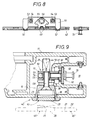
- the control pin 25 of the rotary thrust member protrudes thereby into the interior of the sash 17 and is there non-rotatably, but axially displaceably coupled with an edge gear 50 shown in FIGS. 3, 8 and 9, which is part of a linkage 60 guided in the sash 17 in a longitudinally movable manner.
- the linkage 60 comprises a drive rod 61 which is longitudinally guided on a cover rail 62 and is moved longitudinally by the action of the edge gear 50.
- the cover rail 62 carries the drive rod 61, which is longitudinally movable thereon.
- the linkage 60 is mounted in a longitudinal groove 19 of the casement 17 by the cover rail 62 being supported on edge strips 49 in the interior of the groove and being fastened to a groove base 59.
- the groove base 59 has an opening at one point for the implementation of the edge gear 50 shown in FIG. 9 into the interior of the wing.
- the edge gear 60 comprises, as can be seen from the rear view of FIG. 3 and the sectional view of FIG. 8, a gear housing 51 consisting of two cranked plates, which are riveted to the cover rail 62 via a pair of pins 52 at the end. 3, the drive rod 61 is provided with a longitudinal slot 71 which surrounds the gear housing 51, but is long enough to permit the required longitudinal displacement of the drive rod 61 in the direction of arrow 65. Between the two housing plates 51 there are spacer blocks 53 which carry threaded receptacles 54 which are used to screw in fastening screws 58 which can be seen in FIG. 9. The fastening screws 58 hold the housing shell 30 in its installed position in the casement 17 and thereby penetrate the bores 37 already mentioned above in the reinforced shell bottom wall 36.
- the gear wheel 55 is rotatably supported in the housing plates 51 and has a coupling receptacle 56 with an edge profile, which is designed here as a hollow square.
- the working section 29 of the control pin 25 engages in the coupling receptacle 56 and thus produces a rotationally fixed connection, because the working section 29 has an edge profile that is complementary to the coupling receptacle 56.
- there is a play between the working section 29 and the coupling receptacle 56 which has an axial mobility 44 of the bolt 25 that can be seen in FIG. 9 permitted relative to the bevel gear 50.
- the long cross bar determined by the radial arms 21 only partially fills the shell opening 31, which is designed here as a longitudinal gap.
- the radial arms 21 have a gap width adapted to the arm width 67, but their arm length 66 is shorter than the gap length, which is why residual openings 57 already remain there in the initial rotational position 20 shown in FIGS. 4 and 5.
- the remaining openings 57 are dimensioned large enough to insert fingers behind the radial arms 21 of the cross handle 20 in the insertion position 45 of FIG. 4, which make it possible for the entire rotary pushing element in the sense of the pushing arrow 44 already mentioned into the extension position shown in FIG. 7 45 'to be transferred.
- the other axial end position of the thrust member which is determined by the abovementioned flange flange 39 abutting the end face of the bush 35 on the control bolt 25 from the housing shell 30.
- the control pin 25 is also carried along and can be axially displaced with its angular working section 29 in the coupling receptacle 56. As can be seen from FIG.
- the working section has a sufficient bolt length 64 so that there is also a rotationally fixed coupling between the gear wheel 55 and the cross handle 20 in the extended position 45 'of the rotating pushing element.
- the cross handle 20 jumps out of the built-in housing shell 30 and can be gripped comfortably by hand in order to transfer it to another rotational end position shown in FIG. 6 in the sense of the arrow 47 indicated in FIG.
- the linkage 60 may be in its unlocked position; the closing element 70 has come free from its counter-closing part in the frame 13.
- the bevel gear 60 there are radial stops which fix the two end positions 20, 20 'corresponding to FIGS. 6 on the one hand and 7 on the other hand.
- these consist of the ends 73 of the longitudinal slot 71 in the drive rod 61. In the rotational end positions, the slot end 73 abuts the respective housing edge 72.
- the cross handle can be transferred to the already mentioned rotational end position 20' by the twist 42 recognizable from FIG. 6. Then the cross handle can be moved back into its insertion position, which, however, because of the twisting 20 ′ that is achieved, is an insertion rotation position 45 ′′ that is offset in relation to FIG. 4 and shown in FIG. 6.
- the two pairs of arms 21; 22 swapped their position in the housing shell 30 with respect to the starting rotational position 20 of FIG. 4.
- the radial arm 21 also has an arm width 67 and an arm thickness 68 which is adapted to the given widths of the recess 33. 6, the twisted cross handle 20 'is also flush in the shell opening 31, which corresponds to the flushness in FIG. 5.
- the long radial arms 21 are transverse and signal the operator that the linkage 60 of this wing is in its other working position, for. B. the unlocked position, in which the given position of the sliding leaf 11 is not locked in the frame 13.
- an unwanted backward rotation 42 of the cross handle is initially not possible due to the engagement of the radial arms 21 in the shell recess 33; the given unlocking position is secured in the insertion rotational position 45 ′′ by the engagement of the cross handle 20 ′ as described.
- the cross handle In order to move the linkage back into its locking position of FIG. 4, the cross handle must first be moved axially again in the direction of the pushing arrow 44 into its extended position, where it can then be moved back into its untwisted extended position 45 ′ shown in FIG. 7.
- the linkage 60 is transferred back into its locking position via the rotationally fixed axial coupling of 29, 56. Then the cross handle can be pushed back in the pushing direction 44 into the wing 17 and enters the insertion position 45 already described in FIG. 4. Due to the engagement relationship between the short auxiliary arms 22 and the recess 33, the given rotary end position 20 of the cross handle is also secured in an analogous manner. The cross handle cannot be inadvertently turned in both insertion positions 45, 45 ''.
- the auxiliary arms 22 are in alignment with the shell opening 31, which is why they move into the interior of the shell opening 31 in the inserted rotational position 45' 'of the link.
- the arm length 69 of the auxiliary arms 22 is so much shorter that the bores 67 in the shell bottom 34 become visible and therefore, as can be seen from the screw heads 38 of FIG. 6, make the fastening screws 58 easily accessible for mounting or dismounting the unit 40 on the wing 17.
- the long radial arms 21 cover these fastening points 36, 38, thus ensuring a pleasing appearance of the closure 10 according to the invention.
- a handle designed as a toggle could also be useful, in which only the two radial arms 21 are provided and the auxiliary arms 22 are missing.
- the described axial extension 44 could also take place in that the handle 20 is axially displaceable on its control pin 25.
- the control pin 25 in this handle extension 44 could be coupled completely or at least partially immovably to the edge gear. An axially fixed cohesion between the control pin and the handle is then dispensed with, but their rotationally fixed connection is retained.
- closure according to the invention also on other sashes which are movable differently with respect to their frame, e.g. B. on pivoting or rotating wings.
- the closure according to the invention can be used wherever you want to use its space-saving structure and its convenient operation.
Landscapes
- Wing Frames And Configurations (AREA)
Applications Claiming Priority (2)
| Application Number | Priority Date | Filing Date | Title |
|---|---|---|---|
| DE19904036250 DE4036250A1 (de) | 1990-11-14 | 1990-11-14 | Verschluss fuer den fluegel, insbesondere schiebefluegel eines fensters, einer tuer o. dgl. |
| DE4036250 | 1990-11-14 |
Publications (2)
| Publication Number | Publication Date |
|---|---|
| EP0485767A1 true EP0485767A1 (fr) | 1992-05-20 |
| EP0485767B1 EP0485767B1 (fr) | 1995-02-22 |
Family
ID=6418245
Family Applications (1)
| Application Number | Title | Priority Date | Filing Date |
|---|---|---|---|
| EP19910117960 Expired - Lifetime EP0485767B1 (fr) | 1990-11-14 | 1991-10-22 | Verrouillage pour l'aile, en particulier l'aile coulissante d'une fenêtre, porte etc. |
Country Status (3)
| Country | Link |
|---|---|
| EP (1) | EP0485767B1 (fr) |
| DE (1) | DE4036250A1 (fr) |
| ES (1) | ES2068462T3 (fr) |
Cited By (6)
| Publication number | Priority date | Publication date | Assignee | Title |
|---|---|---|---|---|
| EP1167660A1 (fr) * | 2000-06-30 | 2002-01-02 | Ferco International Ferrures et Serrures de Bâtiment | Organe de manoeuvre escamotable de fouillot de boítier de crémone ou analogue |
| EP1167659A1 (fr) * | 2000-06-28 | 2002-01-02 | Ferco International Ferrures et Serrures de Bâtiment | Organe de manoeuvre escamotable de fouillot de boítier de crémone ou analogue |
| FR2811005A1 (fr) * | 2000-06-28 | 2002-01-04 | Ferco Int Usine Ferrures | Organe de manoeuvre escamotable de fouillot de boitier de cremone ou analogue |
| ITBS20080181A1 (it) * | 2008-10-15 | 2010-04-16 | Bordogna S P A | Gruppo di apertura/chiusura di un'anta di una cassaforte |
| EP2365164A3 (fr) * | 2010-03-11 | 2017-05-03 | KFV Karl Fliether GmbH & Co. KG | Dispositif de verrouillage |
| EP2213816A3 (fr) * | 2009-01-28 | 2018-01-10 | J. Banks & Co. Ltd. | Poignée pour porte pliable et coulissante |
Families Citing this family (5)
| Publication number | Priority date | Publication date | Assignee | Title |
|---|---|---|---|---|
| DE19937401C1 (de) * | 1999-08-07 | 2001-03-01 | Weidtmann Wilhelm Kg | Verschlussbetätiger für Flügel von Fenstern, Türen od. dgl., insbesondere von Schiebeflügeln |
| DE10017628A1 (de) * | 2000-04-05 | 2001-10-11 | Volkswagen Ag | Griff für Fahrzeuge, insbesondere Türzuziehgriff |
| DE10204744B4 (de) * | 2002-02-06 | 2010-11-04 | Wilhelm Weidtmann Gmbh & Co Kg | Verschluss an einem Flügel eines Fensters, einer Tür od. dgl. mit einem Klappgriff |
| DE102010031110A1 (de) | 2010-07-08 | 2012-01-12 | Aug. Winkhaus Gmbh & Co. Kg | Hebelgetriebe zum Antrieb einer Treibstange eines Treibstangenbeschlages |
| DE202014101108U1 (de) * | 2014-03-12 | 2015-06-16 | SCHÜCO International KG | Riegelstangenbeschlag |
Citations (4)
| Publication number | Priority date | Publication date | Assignee | Title |
|---|---|---|---|---|
| US3438227A (en) * | 1966-07-13 | 1969-04-15 | Illinois Lock Co | Pop handle lock |
| US4552001A (en) * | 1983-12-06 | 1985-11-12 | Medeco Security Locks, Inc. | High security T-handle assembly |
| US4899561A (en) * | 1989-04-10 | 1990-02-13 | Fort Lock Corporation | Pop-out handle lock assembly |
| US4966018A (en) * | 1988-02-24 | 1990-10-30 | Peter Hauber | Low profile, secure camper shell latch |
Family Cites Families (7)
| Publication number | Priority date | Publication date | Assignee | Title |
|---|---|---|---|---|
| FR456490A (fr) * | 1913-04-10 | 1913-08-27 | Edmund Herbert Banks | Mécanisme à loquet à ressorts double pour portes |
| AT303565B (de) * | 1970-12-21 | 1972-11-27 | Lapp Finze Ag | Stellhebel, insbesondere für den Drehkippflügel eines Fensters od.dgl. |
| DE2730407C2 (de) * | 1977-07-06 | 1987-01-15 | V. Kann Rasmussen Holding A/S, Soeborg | Vorrichtung zur Verriegelung eines beweglichen Flügelrahmens an einem Fensterrahmen |
| DE8023160U1 (de) * | 1980-08-30 | 1980-12-04 | Wilh. Engstfeld Gmbh U. Co Kg, 5628 Heiligenhaus | Betaetigungsgriff, insbesondere fenstergriffolive |
| DE3036296A1 (de) * | 1980-09-26 | 1982-05-27 | Brown, Boveri & Cie Ag, 6800 Mannheim | Tuerverschluss |
| DE3306728A1 (de) * | 1983-02-25 | 1984-08-30 | Thomas J. Parkland Fla. Metzger | Verriegelungsvorrichtung |
| DE8614642U1 (de) * | 1986-05-30 | 1986-07-24 | Hoppe Gmbh & Co Kg, 3570 Stadtallendorf | Betätigungsgriff |
-
1990
- 1990-11-14 DE DE19904036250 patent/DE4036250A1/de not_active Withdrawn
-
1991
- 1991-10-22 EP EP19910117960 patent/EP0485767B1/fr not_active Expired - Lifetime
- 1991-10-22 ES ES91117960T patent/ES2068462T3/es not_active Expired - Lifetime
Patent Citations (4)
| Publication number | Priority date | Publication date | Assignee | Title |
|---|---|---|---|---|
| US3438227A (en) * | 1966-07-13 | 1969-04-15 | Illinois Lock Co | Pop handle lock |
| US4552001A (en) * | 1983-12-06 | 1985-11-12 | Medeco Security Locks, Inc. | High security T-handle assembly |
| US4966018A (en) * | 1988-02-24 | 1990-10-30 | Peter Hauber | Low profile, secure camper shell latch |
| US4899561A (en) * | 1989-04-10 | 1990-02-13 | Fort Lock Corporation | Pop-out handle lock assembly |
Cited By (8)
| Publication number | Priority date | Publication date | Assignee | Title |
|---|---|---|---|---|
| EP1167659A1 (fr) * | 2000-06-28 | 2002-01-02 | Ferco International Ferrures et Serrures de Bâtiment | Organe de manoeuvre escamotable de fouillot de boítier de crémone ou analogue |
| FR2811005A1 (fr) * | 2000-06-28 | 2002-01-04 | Ferco Int Usine Ferrures | Organe de manoeuvre escamotable de fouillot de boitier de cremone ou analogue |
| FR2811004A1 (fr) * | 2000-06-28 | 2002-01-04 | Ferco Int Usine Ferrures | Organe de manoeuvre escamotable de fouillot de boitier de cremone ou analogue |
| EP1167660A1 (fr) * | 2000-06-30 | 2002-01-02 | Ferco International Ferrures et Serrures de Bâtiment | Organe de manoeuvre escamotable de fouillot de boítier de crémone ou analogue |
| ITBS20080181A1 (it) * | 2008-10-15 | 2010-04-16 | Bordogna S P A | Gruppo di apertura/chiusura di un'anta di una cassaforte |
| EP2177699A1 (fr) * | 2008-10-15 | 2010-04-21 | Bordogna S.p.A. | Dispositif d'ouverture/fermeture pour une porte de coffre fort |
| EP2213816A3 (fr) * | 2009-01-28 | 2018-01-10 | J. Banks & Co. Ltd. | Poignée pour porte pliable et coulissante |
| EP2365164A3 (fr) * | 2010-03-11 | 2017-05-03 | KFV Karl Fliether GmbH & Co. KG | Dispositif de verrouillage |
Also Published As
| Publication number | Publication date |
|---|---|
| ES2068462T3 (es) | 1995-04-16 |
| DE4036250A1 (de) | 1992-05-21 |
| EP0485767B1 (fr) | 1995-02-22 |
Similar Documents
| Publication | Publication Date | Title |
|---|---|---|
| EP0942135B2 (fr) | Dispositif de verrouillage | |
| DE3822050C2 (fr) | ||
| DE3600211C1 (de) | Fenster- und Tuerbeschlag | |
| EP0485767B1 (fr) | Verrouillage pour l'aile, en particulier l'aile coulissante d'une fenêtre, porte etc. | |
| EP1049846B1 (fr) | Serrure pour porte en verre avec un element lateral fixe en verre | |
| DE3425565A1 (de) | Treibstangenschloss | |
| EP1022421B1 (fr) | Dispositif déflecteur pour panneau basculant ou oscillo-battant monté pivotant sur un cadre | |
| EP0361001B1 (fr) | Serrure à crochet | |
| DE29513227U1 (de) | Treibstangen-Antrieb | |
| DE69800295T2 (de) | Treibstangenbeschlag oder Treibstangenverschluß für Tür, Fenster oder dergl. | |
| EP0844348A1 (fr) | Penture pour portes ou fenêtres | |
| DE60009792T2 (de) | Vorrichtung zum Antrieb einer Nuss | |
| EP0761920B2 (fr) | Fenêtre/porte avec battant pivotant et/ou basculant | |
| EP3018269B1 (fr) | Systeme de poignee pour une fenetre ou similaire et fenetre ou similaire dotee du systeme de poignee | |
| EP1144780B1 (fr) | Configuration rotorique pour systeme de ferrures | |
| EP0806534B1 (fr) | Crémone | |
| EP0748911B1 (fr) | Crémone pour le battant d'une fenêtre ou d'une porte | |
| DE4200868A1 (de) | Zusatz-schliesseinrichtung fuer fenster | |
| DE4014042A1 (de) | Treibstangenschloss | |
| EP0667432B1 (fr) | Dispositif de verrouillage supplémentaire pour fenêtre ou similaires | |
| EP0930410A1 (fr) | Poignée de manoeuvre | |
| WO1993004253A1 (fr) | Porte de securite et dispositif de securite pour le montage dans une porte | |
| EP0574594B1 (fr) | Ferrure de porte | |
| EP0573820A1 (fr) | Ferrure pour un anneau coulissant de fenêtre, de porte ou similaire | |
| DE69931722T2 (de) | Treibstange oder Treibstangenschloss für Türen, Fenster oder dergleichen |
Legal Events
| Date | Code | Title | Description |
|---|---|---|---|
| PUAI | Public reference made under article 153(3) epc to a published international application that has entered the european phase |
Free format text: ORIGINAL CODE: 0009012 |
|
| AK | Designated contracting states |
Kind code of ref document: A1 Designated state(s): ES FR GR IT |
|
| 17P | Request for examination filed |
Effective date: 19920710 |
|
| 17Q | First examination report despatched |
Effective date: 19930916 |
|
| GRAA | (expected) grant |
Free format text: ORIGINAL CODE: 0009210 |
|
| ITF | It: translation for a ep patent filed | ||
| AK | Designated contracting states |
Kind code of ref document: B1 Designated state(s): ES FR GR IT |
|
| PG25 | Lapsed in a contracting state [announced via postgrant information from national office to epo] |
Ref country code: GR Free format text: LAPSE BECAUSE OF FAILURE TO SUBMIT A TRANSLATION OF THE DESCRIPTION OR TO PAY THE FEE WITHIN THE PRESCRIBED TIME-LIMIT Effective date: 19950222 |
|
| ET | Fr: translation filed | ||
| REG | Reference to a national code |
Ref country code: ES Ref legal event code: FG2A Ref document number: 2068462 Country of ref document: ES Kind code of ref document: T3 |
|
| PLBE | No opposition filed within time limit |
Free format text: ORIGINAL CODE: 0009261 |
|
| STAA | Information on the status of an ep patent application or granted ep patent |
Free format text: STATUS: NO OPPOSITION FILED WITHIN TIME LIMIT |
|
| 26N | No opposition filed | ||
| PGFP | Annual fee paid to national office [announced via postgrant information from national office to epo] |
Ref country code: FR Payment date: 20000927 Year of fee payment: 10 |
|
| PGFP | Annual fee paid to national office [announced via postgrant information from national office to epo] |
Ref country code: ES Payment date: 20001020 Year of fee payment: 10 |
|
| PG25 | Lapsed in a contracting state [announced via postgrant information from national office to epo] |
Ref country code: ES Free format text: LAPSE BECAUSE OF NON-PAYMENT OF DUE FEES Effective date: 20011023 |
|
| PG25 | Lapsed in a contracting state [announced via postgrant information from national office to epo] |
Ref country code: FR Free format text: LAPSE BECAUSE OF NON-PAYMENT OF DUE FEES Effective date: 20020628 |
|
| REG | Reference to a national code |
Ref country code: FR Ref legal event code: ST |
|
| REG | Reference to a national code |
Ref country code: ES Ref legal event code: FD2A Effective date: 20021113 |
|
| PG25 | Lapsed in a contracting state [announced via postgrant information from national office to epo] |
Ref country code: IT Free format text: LAPSE BECAUSE OF NON-PAYMENT OF DUE FEES;WARNING: LAPSES OF ITALIAN PATENTS WITH EFFECTIVE DATE BEFORE 2007 MAY HAVE OCCURRED AT ANY TIME BEFORE 2007. THE CORRECT EFFECTIVE DATE MAY BE DIFFERENT FROM THE ONE RECORDED. Effective date: 20051022 |