EP0573820A1 - Ferrure pour un anneau coulissant de fenêtre, de porte ou similaire - Google Patents
Ferrure pour un anneau coulissant de fenêtre, de porte ou similaire Download PDFInfo
- Publication number
- EP0573820A1 EP0573820A1 EP93108075A EP93108075A EP0573820A1 EP 0573820 A1 EP0573820 A1 EP 0573820A1 EP 93108075 A EP93108075 A EP 93108075A EP 93108075 A EP93108075 A EP 93108075A EP 0573820 A1 EP0573820 A1 EP 0573820A1
- Authority
- EP
- European Patent Office
- Prior art keywords
- actuating
- wing
- locking linkage
- fitting
- opening device
- Prior art date
- Legal status (The legal status is an assumption and is not a legal conclusion. Google has not performed a legal analysis and makes no representation as to the accuracy of the status listed.)
- Granted
Links
Images


Classifications
-
- E—FIXED CONSTRUCTIONS
- E05—LOCKS; KEYS; WINDOW OR DOOR FITTINGS; SAFES
- E05D—HINGES OR SUSPENSION DEVICES FOR DOORS, WINDOWS OR WINGS
- E05D15/00—Suspension arrangements for wings
- E05D15/06—Suspension arrangements for wings for wings sliding horizontally more or less in their own plane
- E05D15/10—Suspension arrangements for wings for wings sliding horizontally more or less in their own plane movable out of one plane into a second parallel plane
- E05D15/1005—Suspension arrangements for wings for wings sliding horizontally more or less in their own plane movable out of one plane into a second parallel plane the wing being supported on arms movable in horizontal planes
- E05D15/1013—Suspension arrangements for wings for wings sliding horizontally more or less in their own plane movable out of one plane into a second parallel plane the wing being supported on arms movable in horizontal planes specially adapted for windows
-
- E—FIXED CONSTRUCTIONS
- E05—LOCKS; KEYS; WINDOW OR DOOR FITTINGS; SAFES
- E05D—HINGES OR SUSPENSION DEVICES FOR DOORS, WINDOWS OR WINGS
- E05D15/00—Suspension arrangements for wings
- E05D15/28—Suspension arrangements for wings supported on arms movable in horizontal plane
- E05D15/32—Suspension arrangements for wings supported on arms movable in horizontal plane with two pairs of pivoted arms
- E05D15/34—Suspension arrangements for wings supported on arms movable in horizontal plane with two pairs of pivoted arms with wings opening parallel to themselves
-
- E—FIXED CONSTRUCTIONS
- E05—LOCKS; KEYS; WINDOW OR DOOR FITTINGS; SAFES
- E05F—DEVICES FOR MOVING WINGS INTO OPEN OR CLOSED POSITION; CHECKS FOR WINGS; WING FITTINGS NOT OTHERWISE PROVIDED FOR, CONCERNED WITH THE FUNCTIONING OF THE WING
- E05F11/00—Man-operated mechanisms for operating wings, including those which also operate the fastening
- E05F11/02—Man-operated mechanisms for operating wings, including those which also operate the fastening for wings in general, e.g. fanlights
- E05F11/08—Man-operated mechanisms for operating wings, including those which also operate the fastening for wings in general, e.g. fanlights with longitudinally-moving bars guided, e.g. by pivoted links, in or on the frame
- E05F11/12—Mechanisms by which the bar shifts the wing
- E05F11/14—Mechanisms by which the bar shifts the wing directly, i.e. without links, shifting the wing, e.g. by rack and gear or pin and slot
- E05F11/145—Mechanisms by which the bar shifts the wing directly, i.e. without links, shifting the wing, e.g. by rack and gear or pin and slot by pin and slot
-
- E—FIXED CONSTRUCTIONS
- E05—LOCKS; KEYS; WINDOW OR DOOR FITTINGS; SAFES
- E05F—DEVICES FOR MOVING WINGS INTO OPEN OR CLOSED POSITION; CHECKS FOR WINGS; WING FITTINGS NOT OTHERWISE PROVIDED FOR, CONCERNED WITH THE FUNCTIONING OF THE WING
- E05F11/00—Man-operated mechanisms for operating wings, including those which also operate the fastening
- E05F11/02—Man-operated mechanisms for operating wings, including those which also operate the fastening for wings in general, e.g. fanlights
- E05F11/08—Man-operated mechanisms for operating wings, including those which also operate the fastening for wings in general, e.g. fanlights with longitudinally-moving bars guided, e.g. by pivoted links, in or on the frame
- E05F11/12—Mechanisms by which the bar shifts the wing
- E05F11/24—Mechanisms by which the bar shifts the wing shifting the wing by pivotally-connected members (moving) in a plane parallel to the pivot axis of the wing
-
- E—FIXED CONSTRUCTIONS
- E05—LOCKS; KEYS; WINDOW OR DOOR FITTINGS; SAFES
- E05Y—INDEXING SCHEME ASSOCIATED WITH SUBCLASSES E05D AND E05F, RELATING TO CONSTRUCTION ELEMENTS, ELECTRIC CONTROL, POWER SUPPLY, POWER SIGNAL OR TRANSMISSION, USER INTERFACES, MOUNTING OR COUPLING, DETAILS, ACCESSORIES, AUXILIARY OPERATIONS NOT OTHERWISE PROVIDED FOR, APPLICATION THEREOF
- E05Y2900/00—Application of doors, windows, wings or fittings thereof
- E05Y2900/10—Application of doors, windows, wings or fittings thereof for buildings or parts thereof
- E05Y2900/13—Type of wing
- E05Y2900/132—Doors
-
- E—FIXED CONSTRUCTIONS
- E05—LOCKS; KEYS; WINDOW OR DOOR FITTINGS; SAFES
- E05Y—INDEXING SCHEME ASSOCIATED WITH SUBCLASSES E05D AND E05F, RELATING TO CONSTRUCTION ELEMENTS, ELECTRIC CONTROL, POWER SUPPLY, POWER SIGNAL OR TRANSMISSION, USER INTERFACES, MOUNTING OR COUPLING, DETAILS, ACCESSORIES, AUXILIARY OPERATIONS NOT OTHERWISE PROVIDED FOR, APPLICATION THEREOF
- E05Y2900/00—Application of doors, windows, wings or fittings thereof
- E05Y2900/10—Application of doors, windows, wings or fittings thereof for buildings or parts thereof
- E05Y2900/13—Type of wing
- E05Y2900/148—Windows
Definitions
- the invention relates to a fitting for sliding sashes of windows, doors or the like, which - according to the preamble of claim 1- for opening, can first be lifted perpendicularly to the plane of the frame and can then be moved parallel to the frame level behind an adjacent sash or a fixed field, in which there are upper and lower rails on the frame for engaging elements of the sash extension arms of upper opening devices or of lower running members of the sash, to which an actuating and locking linkage is assigned in the fitting fold of the sash - behind the sash flap, wherein each arm at least the upper opening device with its engaging element in each position of the wing is on the one hand in constant engagement with the upper running rail arranged in front of the inner frame level, while on the other hand each upper opening device is releasably via a driver with the actuating and controllable from a hand lever Locking linkage is connected.
- DE-C 30 50 971 and DE-C 40 16 341 also each disclose a generic fitting which has an opening mechanism in which the upper wing extension arms are independent of the opening arms of the lower running members for the actuating and locking linkage let the wing steer.
- the sash can thus be forcibly pressed on and off via the hand lever relative to the frame and consequently brought into an additional tilt opening position relative to the frame, in which the frame cannot be moved parallel to the frame plane.
- a significant inadequacy of the known fittings is based on the fact that either all of the wing extension arms (DE-U 76 12 109 and DE-A 26 33 369) or at least the upper wing extension arms of the opening mechanism which also allows the wing to be tilted open (DE-C 30 50 971 and DE-C 40 16 341) not only require considerable installation space between the fitting rebate of the sash and the rebate peripheral surface of the frame, but also must also have extension sections which are guided from the rebate space in front of the inner surface of the frame so that they can be over there Engagement elements can interact with the lower and the upper, but at least with the upper track.
- the aim of the present invention is to provide a fitting of the generic type for sliding sashes of windows, doors or the like, in which the installation position of at least the opening devices forming the upper opening mechanism for the sash is determined exclusively by the installation position of the running rails interacting with them via the engaging elements on the inner surface of the frame, while their assignment to the actuating and locking linkage provided in the fitting fold of the leaf corresponds to the different Needs, e.g. B. can be varied with respect to different groove positions for fitting installation.
- each upper display device with a fixed base and all its movable members, for. B. is arranged with a bearing and guide plate as well as a raising arm, control arm and drive or adjusting cams on the sash outside the fitting rebate, and that only the movable driver of each of the upper exhibiting devices and attachment or connection approaches of their fixed base overlap towards the fitting fold and to the actuating and locking linkage located there.
- a further development of the invention provides that the driver of the movable members and the attachment or connection lugs of the fixed base of each upper opening device can be connected to the actuating or locking linkage in at least two different transverse positions.
- the fastening or connecting lugs of the fixed base contain recesses which have an approximately 8-shaped outline shape and are formed, for example, by two merging holes or the like.
- the fastening or connecting lugs of the fixed base can also have material projections on their underside, which form-fit in recesses provided for this purpose, for. B. slots, of faceplates and faceplate of the actuating and locking linkage.
- each upper opening device on the wing can be received in a recess, in particular a cutout or notch, of the flap and can be supported and fastened therein with its base.
- the driver of the movable members extends between two fastening or connecting lugs of the fixed base, which are provided next to one another at a distance, towards the actuating or locking linkage, the space available on the fitting fold of the wing can be optimally used for its accommodation.
- the actuating and locking linkage consists of a gear which can be moved by a handle, of corner deflections coupled therewith, and of intermediate pieces, by means of which drive connections to further corner deflections are formed.
- a coupling piece of the actuating and locking linkage for the driver of the movable members of an upper opening device sits on the upper horizontal leg of a corner drive and that the upper horizontal faceplate leg of the respective corner drive fixes or connects to the corner Fixed base of an upper display device contains. This makes it possible to create hardware units, each consisting of a corner drive and an opening device. These units can then either be pre-assembled at the factory and matched to different installation conditions, or they can be put together by the window builder or striker when the installation work is carried out to meet the respective requirements.
- the actuating and locking linkage comprises four identical corner deflections, two of which are assigned to the upper and the lower wing corners, the coupling pieces on the horizontal leg of the lower corner deflections each having a fixed, at the bottom Cladding frame spar are assigned to a striking plate and can form a tilt lock for the sash when this is brought into a ventilation tilt position in the area of the opening of the frame to be closed with it.
- the overall construction of the fitting is particularly useful if, according to another training proposal, one and the same corner drive can optionally be installed in the sash in a horizontally and / or vertically turned position and thus on both the right and left as well as on the upper and lower ones Wing corners can be used.
- each upper opening device is formed by an opening arm and a control arm which is articulated only pivotably on the one hand and on the other on the fixed base, and on which a drive or adjusting cam guided on the fixed base engages longitudinally
- the invention also provides that the control arm of the display device engages under a projection on the fixed base with a nose protruding beyond its articulation on the display arm in the closed switch position of the actuating and locking linkage.
- This measure counteracts a lifting of the control arm from the drive or actuating cam interacting with it when the sash is in the closed position and thus prevents an attempted break-in from the outside.
- An inventive fitting in which the control arm of the opening device - at least on the underside - a z.
- S- or Z-shaped curved control curve with which the drive or actuating cam is in permanent engagement over its entire travel range can be improved according to the invention in that the control curve of the control arm and the drive or actuating cam have an outer contour in which two different support or abutments are formed in the tilt-switch position of the actuating and locking linkage between the drive or actuating cam and the control cam of the control arm.
- loads acting on the wing in the tilted ventilation position for example wind forces, are particularly well absorbed in this way, i. H.
- the sash can be fixed against the frame in its tilting position almost without rattling.
- the articulation of the control arm on the fixed base, the articulation of the control arm on the extension arm and the point of application of the drive or actuating cam on the control cam in the toggle switch position of the actuating and locking linkage at least are approximately on a straight line.
- the driver of the opening device can be designed in the form of a fork, and in this case comprises the coupling piece of the actuating and locking linkage in a form-fitting manner in its displacement direction.
- an extension arm pivotally engages the stationary base to use a hammer-head-shaped rivet as an engagement member in the longitudinal guide slot of the stationary base and to fix it in a rotationally fixed manner in the opening arm.
- the hammer-head-shaped rivet can then simply be inserted into the longitudinal slot of the fixed base.
- the hammer head After pivoting the extension arm into the connection position to the control arm, the hammer head then engages under the longitudinal edges of the longitudinal slot of the stationary base and is secured there against lifting.
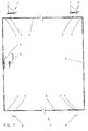
- Fig. 1 of the drawing shows a schematically simplified representation of a connecting rod fitting 1, which is designed as a so-called central lock and can be installed in the (not shown here) wing of a window of a door or the like.
- the espagnolette fitting 1 is a functionally essential component of the overall fitting for a sliding sash of windows, doors or the like, which can first be lifted from the frame perpendicularly to the plane of a frame (also not shown here) and then parallel to the frame level behind an adjacent sash or a fixed field is movable.
- the sash can additionally be moved into a tilt-opening ventilation position relative to the frame, in which case it is a tilt-parallel sliding window or such a door.
- upper and lower guide rails are provided on the frame for the engagement elements of the wing raising arms of upper raising devices or of lower running members of the wing, to which the actuating and locking linkage of the espagnolette fitting 1 is provided in the fitting fold of the wing assigned.
- Each opening arm of at least the upper opening devices is in constant engagement with its engaging element in every position of the sash on the one hand with the upper running rail arranged in front of the inner frame level, while on the other hand each upper opening device can be released via a driver with the actuating and locking linkage that can be controlled by a hand lever the connecting rod fitting 1 is connected.
- the drive rod fitting 1 which is designed as a central lock, is guided along all four spars of the wing (not shown there) and is accommodated on it in the usual manner in the fitting fold.
- a corner deflection 2 installed, ie there are two upper and two lower corner deflections 2, which are in a geared connection with each other via intermediate pieces.
- the drive rod fitting 1 is operated via a handle 3 and a gear 4 which can be operated with the aid thereof and which is designed such that it converts the rotary movement of the handle 3 into a pushing movement of the actuating and locking linkage.
- the push rod moved by the gear 4 engages a corner drive 2 at the top and bottom.
- Each of these corner deflections 2 is connected by a horizontal intermediate piece 5 to a further corner deflection 2, these two corner deflections 2 being in turn coupled by a vertical intermediate piece 5.
- the two upper corner deflections 2 of the espagnolette fitting 1 are each assigned an opening device 6, which is mounted on the wing by means of fasteners 7, for example screws, and overlaps towards the frame.
- the movement control of the opening devices 6 is effected via the actuating and locking linkage of the connecting rod fitting 1, specifically by means of coupling pieces 9 which are provided on the upper horizontal leg of each upper corner deflection 2 and are arranged to be displaceable to a limited extent in the longitudinal direction of the upper wing spar.
- the coupling piece 9 of the two lower corner deflections 2 can come into operative connection with striking plates 8 fastened to the frame, so that a coupling piece 9 and a striking plate 8 each form a so-called tilt lock for the tilt opening of the wing.
- the striking plates 8 In order to secure the wing opened in the tilted position against lifting out, the striking plates 8 have an upwardly open C cross section, while the coupling pieces 9 are complementarily profiled, for example have an I or inverted T cross section.
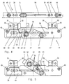
- the upper left corner deflection 2 and the upper left opening device 6 of the drive rod fitting 1 according to FIG. 1 can be seen on a larger scale, for example only. It can be seen that there is a structural separation between the opening device 6 and the corner guide 2 and that the coupling piece 9 can be used for the gear coupling of the opening device 6 with the corner link 2, which limits along the upper, horizontal leg of a faceplate 16 of the corner link 2 is guided longitudinally.
- the coupling piece 9 is connected to the drive rod 15, which is concealed under the faceplate angle 16 of the corner deflection 2.
- screws 7 or similar fastening elements can be used to fasten the opening device 6 to the wing.
- FIG. 3 shows a partial cross section through the upper horizontal spar of the wing 11, a cross section through the upper horizontal spar of the frame 1 and a cross section of the seal 12 arranged between them.
- the wing 11 is located relative to the frame 10 in the closed position.
- Fig. 3 of the drawing you can also see the arrangement of the espagnolette fitting 1 and the cooperating Ausstellvorrichung 6 in the area between the upper horizontal spar of the wing 11 and the upper horizontal spar of the frame 10.
- Espagnolette fitting 1 or from the corner deflection 2 In Fig. 3 the upper horizontal leg of the faceplate 16 and the drive rod 15 can be seen, which are received in a stepped profile groove 44 which is molded or incorporated into the fitting fold 46 on the wing 11.
- Fig. 9 of the drawing also shows that the stepped profile groove 44 is in the fitting rebate 46 behind the flap 43 of the wing 11 and has, for example, approximately a T-cross-sectional shape.
- the opening device 6 is arranged in this recess 47 both with a fixed base 17, 17a and with all its movable members, which will be described below, in such a way that they are directed outside the actual fitting fold 46 and in front of the inside of the room Face 39 of the frame 10 is located.
- the stationary base 17, 17a of each opening device 6 is formed by a bearing and guide plate 17 and two spacers 17a located on the underside thereof, which, apart from in FIG. 3, can also be seen in FIGS. 2 and 8 of the drawing.
- the stationary base 17 is supported by the spacers 17a, 17a on the base 47a of the recess 47 machined into the rollover 43.
- the stationary base 17, 17a has on its spacers 17a and the section of the bearing and guide plate 17 that is in the cover position, each with attachment or connection lugs 48 that extend in the transverse direction to the fitting fold 46 and to the actuating and locking linkage of the connecting rod fitting located there 1 overlap, as can be seen in particular from FIGS. 3 and 6, but can also be seen in FIG. 4.
- the attachment or connection lugs 48 of the fixed base 17, 17a are supported at least on the upper horizontal leg of the faceplate angle 16, as can be seen in FIG. 3.
- each corner deflection 2 each has several, for example two, slot-like recesses 30 lying one behind the other in the direction of its width for receiving the material projections 18 on the spacers 17a the fixed base 17, 17a.
- Figures 4 to 7 of the drawing show that there is still a further or additional possibility of variably bridging the distance between each opening device and the actuating and locking linkage of the connecting rod fitting 1 in the normal direction to the sash plane.
- the attachment or connection lugs 48 of the bearing and guide plate 17 and the spacers 17a located on the underside thereof are provided with through openings 31 which are delimited in an approximately 8-shaped manner. They can be formed by two merging round holes, which are arranged so that the common central plane extends transversely to the wing plane.
- the center distance between the two round holes of the through openings 31 corresponds to the extent to which the relative position of the opening device 6 to the longitudinal center of the connecting rod fitting 1 or the faceplate angle 16 of the corner deflection can be varied.
- Each of the merging round holes of the 8-shaped through openings 31 can be brought into a cover position with a round hole 45 in the upper horizontal leg of the faceplate 16 of the corner deflection 2, in order then to use fastening screws which fix the transverse position of the opening device 2 relative to the longitudinal center plane of the connecting rod fitting 1 or fix to the corner deflection 2.
- each raising device 6 also has a raising arm 20, a control arm 27 and a drive or adjusting cam 33 as movable members, which are located on the top of the bearing and guide plate 17 are located.
- a movable driver 26 is provided, which extends through a longitudinal slot 50 of the bearing and guide plate 17 and is in fixed connection with the drive or adjusting cam 33.
- the driver 26 has a fork-shaped outline shape and is designed so that it can encompass the coupling cam 9 in the sliding direction, which protrudes from a longitudinal slot 51 in the upper horizontal leg of the faceplate 16 of the corner deflection 2, as is particularly illustrated in Fig. 4 of the drawing.
- the driver 26 is held between two fastening or connecting lugs 48 of the fixed base 17, 17a, which are provided next to one another at a distance, in the longitudinal slot 50 of the bearing and guide plate 17 and can easily be taken from there to the coupling piece 9 of the connecting rod fitting 1 or the corner deflection 2 overlap when both the connecting rod fitting 1 and the opening device 6 are mounted on the wing 11.
- the control arm 27 is mounted on the bearing and guide plate by means of a pivot pin 29, which in turn is connected to the extension arm 20 via a pivot pin 32 after the latter has been suspended in a guide slot 38 via a guide rivet 25 fastened to its front end with a hammer head, which is located in a fixed top piece 19 on the bearing and guide plate 17.
- the guide rivet 25 of the extension arm 20 can be hooked into the guide slot 38 when the latter has been brought into the dash-dotted position shown in FIG. 7.
- the extension arm 20 is then brought to the control arm 27 in the position indicated by solid lines in FIG. 7 so that a connection to the control arm 27 can be established via the pivot pin 32, namely by riveting the same.
- control arm 32 has an approximately S or Z-shaped control cam 52 with which a control pin 34 cooperates, which forms an essential part of the drive or actuating cam 33.
- control pin 34 is located in different longitudinal sections of the control cam 52, such that the control arm is forced between its rest position shown in FIG. 4 and its end position shown in FIG. 5 can be moved around the pivot 29.
- the extension arm 20 can be moved from a parallel position (not shown in the drawing) to the fixed base 17, 17a as far as FIGS. 6 and 7 Removable inclined position to turn the sash 11 from the frame 10 by a certain amount.
- the drive or actuating cam 33 and the control cam 52 assigned to it in the control arm 27 have such a configuration that not only the control pin 34 is engaged in the tilt-open switching position of the drive rod fitting 1, but also still a locking edge 35 of the drive or actuating cam 33 comes into operative connection with a locking edge 41 on the control arm 27 (FIG. 5).
- the control arm 27 and the drive or adjusting cam 33 therefore, there is a double support relative to the fixed base 17, 17a in the tilt-open switch position of the fitting and thus a largely rattle-free fixation of the extension arm 20 in its parking position. If the locking edge 35 of the drive or actuating cam 33 and the abutment edge 41 of the control arm 27 in the functional position shown in FIG. 5 are relatively close to a straight line guided by the two articulation points 29 and 32, stable support is obtained with little effort of the control arm 27 received.
- control arm 27 is provided with a projection 53 projecting beyond its articulation 32 on the extension arm, which in the pivot position of the control arm 27 shown in FIG. 4 shows the attachment piece 19 on the stationary base 17, 17a included.
- This can prevent the control arm 27 from being undesirably raised when the wing 11 is in the closed position over the drive and adjusting cams 33 which are displaceably guided on the stationary base 17, 17a. In this way, attempts to break in from the outside are dealt with in a simple manner.
- a guide pin 21 is seated at the free end of the extension arm 20, which acts as an engagement element with the on the room-side end face of the frame 10, the upper guide rail 23 cooperates.
- the guide pin 21 is, of course, engaged in an engagement element designed as a sliding piece, which is slidably received by the guide rail 23, but which (for the sake of simplicity) is not shown in FIG. 3 of the drawing.
- a cover rail 22 is fastened to the upper horizontal spar of the wing 11 in front of the flap 43, which extends at least over the length of each of the recesses 47, but preferably continuously over the entire length of the wing spar in question extends.
- This cover rails 22 not only bridges the distance between the upper horizontal spar of the wing 11 and the guide rail 23, which is attached to the room-side end face of the frame 10, namely the upper horizontal frame spar. Rather, the opening devices 6 are provided behind the cover rail 22 within the recess 47 of the wing flap 43, as can be easily seen from FIG. 3 of the drawing.
- cover rail 22 must have different fastening positions relative to the upper horizontal spar of the wing 11, provided that the flap 43 has different widths.
- a rollover 43 with a width of 15 mm can be seen in FIG. 10, a rollover 43 with a width of 18 mm in FIG. 11 and a rollover 43 with a width of 22 mm in FIG.
- latching brackets 54 are used, which are essentially shaped, e.g. made of hard plastic, with three legs 55, 56 and 57 facing away from each other. While the legs 55 and 57 serve as latching legs for interacting with latching lugs of the cover rail 22 and each have latching engagements 58 and 59 for this purpose, the leg 56 is provided as a stop leg which has two stop faces 60 and 61 which face away from one another.
- the latching leg 57 of the latching holder 54 lies against the end face of the wing 11 on the room side, while the stop surface 60 of the stop leg 56 rests on the peripheral surface of the flap 43.
- the locking leg 55 is in this case provided obliquely upwards away from the wing 11.
- This installation position of the latch holder 54 is provided when the flap 43 of the wing 11 has a relatively small width of 15 mm, that is, a relatively large distance between the underside of the guide rail 23 and the peripheral surface of the flap 43 must be bridged.
- the latching brackets 54 are installed in such a way that their latching leg 55 rests on the wing end face on the room side, while the stop surface 61 of the stop leg 56 rests on the peripheral surface of the wing flap (FIGS. 11 and 12 ).
- the locking leg 57 is directed obliquely upward away from the wing 11.
- the cover rail 22 is in any case with the locking handles 58 and 59 of the latch holder 54 in the manner of snap and Locked connections coupled, in such a way that their upper boundary edge lies with a certain gap distance in front of the end face of the guide rail 23 or the profile rail 24 connected to it.
Landscapes
- Engineering & Computer Science (AREA)
- Mechanical Engineering (AREA)
- Power-Operated Mechanisms For Wings (AREA)
- Wing Frames And Configurations (AREA)
- Special Wing (AREA)
- Support Devices For Sliding Doors (AREA)
- Operating, Guiding And Securing Of Roll- Type Closing Members (AREA)
- Securing Of Glass Panes Or The Like (AREA)
- Specific Sealing Or Ventilating Devices For Doors And Windows (AREA)
Applications Claiming Priority (2)
| Application Number | Priority Date | Filing Date | Title |
|---|---|---|---|
| DE4218904A DE4218904A1 (de) | 1992-06-09 | 1992-06-09 | Beschlag für einen verschiebbaren Flügel von Fenstern, Türen o. dgl. |
| DE4218904 | 1992-06-09 |
Publications (2)
| Publication Number | Publication Date |
|---|---|
| EP0573820A1 true EP0573820A1 (fr) | 1993-12-15 |
| EP0573820B1 EP0573820B1 (fr) | 1996-02-21 |
Family
ID=6460663
Family Applications (1)
| Application Number | Title | Priority Date | Filing Date |
|---|---|---|---|
| EP93108075A Expired - Lifetime EP0573820B1 (fr) | 1992-06-09 | 1993-05-18 | Ferrure pour un anneau coulissant de fenêtre, de porte ou similaire |
Country Status (4)
| Country | Link |
|---|---|
| EP (1) | EP0573820B1 (fr) |
| AT (1) | ATE134414T1 (fr) |
| DE (2) | DE4218904A1 (fr) |
| DK (1) | DK0573820T3 (fr) |
Cited By (1)
| Publication number | Priority date | Publication date | Assignee | Title |
|---|---|---|---|---|
| CN120506152A (zh) * | 2025-07-18 | 2025-08-19 | 苏州德仕耐五金技术有限公司 | 一种多方位同步拉紧锁闭系统 |
Families Citing this family (3)
| Publication number | Priority date | Publication date | Assignee | Title |
|---|---|---|---|---|
| DE4417842A1 (de) * | 1994-05-20 | 1995-11-23 | Winkhaus Fa August | Teilautomatisch anschlagbares Beschlagssystem für Fenster, Türen oder dergleichen |
| DE29609869U1 (de) * | 1996-06-05 | 1996-07-25 | Siegenia-Frank Kg, 57074 Siegen | Schiebetür, Schiebefenster o.dgl. |
| DE202023102840U1 (de) * | 2023-05-23 | 2023-06-29 | Siegenia-Aubi Kg | Verlagerungsvorrichtung zur zwangsweisen Verlagerung eines Flügels, insbesondere eines Schiebeflügels, eines Fensters oder einer Tür |
Citations (1)
| Publication number | Priority date | Publication date | Assignee | Title |
|---|---|---|---|---|
| DE2633369A1 (de) * | 1976-07-24 | 1978-01-26 | Rudolf Weikert | Schiebetuer, schiebefenster u.dgl. |
-
1992
- 1992-06-09 DE DE4218904A patent/DE4218904A1/de not_active Withdrawn
-
1993
- 1993-05-18 EP EP93108075A patent/EP0573820B1/fr not_active Expired - Lifetime
- 1993-05-18 DE DE59301665T patent/DE59301665D1/de not_active Expired - Fee Related
- 1993-05-18 AT AT93108075T patent/ATE134414T1/de not_active IP Right Cessation
- 1993-05-18 DK DK93108075.8T patent/DK0573820T3/da active
Patent Citations (1)
| Publication number | Priority date | Publication date | Assignee | Title |
|---|---|---|---|---|
| DE2633369A1 (de) * | 1976-07-24 | 1978-01-26 | Rudolf Weikert | Schiebetuer, schiebefenster u.dgl. |
Cited By (2)
| Publication number | Priority date | Publication date | Assignee | Title |
|---|---|---|---|---|
| CN120506152A (zh) * | 2025-07-18 | 2025-08-19 | 苏州德仕耐五金技术有限公司 | 一种多方位同步拉紧锁闭系统 |
| CN120506152B (zh) * | 2025-07-18 | 2025-10-10 | 苏州德仕耐五金技术有限公司 | 一种多方位同步拉紧锁闭系统 |
Also Published As
| Publication number | Publication date |
|---|---|
| DK0573820T3 (da) | 1996-03-18 |
| DE4218904A1 (de) | 1993-12-16 |
| DE59301665D1 (de) | 1996-03-28 |
| ATE134414T1 (de) | 1996-03-15 |
| EP0573820B1 (fr) | 1996-02-21 |
Similar Documents
| Publication | Publication Date | Title |
|---|---|---|
| EP0403731B1 (fr) | Dispositif pour ouverture compas pour panneaux de fenêtres, portes ou similaires | |
| DE4417842A1 (de) | Teilautomatisch anschlagbares Beschlagssystem für Fenster, Türen oder dergleichen | |
| EP4473182B1 (fr) | Agencement de profilé d'une fenêtre ou d'une porte ayant un profilé de châssis/battant, en particulier un profilé de châssis/battant coulissant | |
| EP3102759A1 (fr) | Ferrure d'un battant de fenêtres ou de portes, au moins relevable, mais de préférence également coulissant | |
| DE3041399A1 (de) | Fenster kipp und spaltkipp | |
| DE202008007829U1 (de) | Beschlag für einen verschiebbaren Flügel von Fenstern oder Türen | |
| EP0438740A1 (fr) | Ferrures pour au moins une aile pivotante d'une fenêtre, porte ou semblable | |
| EP0493689B1 (fr) | Tringlerie de commande pour fenêtres, portes ou similaires | |
| EP0485767A1 (fr) | Verrouillage pour l'aile, en particulier l'aile coulissante d'une fenêtre, porte etc. | |
| EP0573820B1 (fr) | Ferrure pour un anneau coulissant de fenêtre, de porte ou similaire | |
| DE102008031877B4 (de) | Setzholzfreies Fenster, Tür oder dgl. | |
| DE29601966U1 (de) | Zusatzschloß für Flügel von Türen, Fenstern o.dgl. | |
| EP0531626B1 (fr) | Ferrure, en particulier pour des battants étant basculés et déplacés d'un plan vers un deuxième plan parallèle | |
| EP0811741B1 (fr) | Ouvrant coulissant d'une porte, fenêtre ou analogue | |
| EP0246431B1 (fr) | Dispositif déflecteur pour panneau basculant, en particulier panneau oscillo-battant ou battant coulissant et basculant, de fenêtres, portes ou similaires | |
| DE9112078U1 (de) | Ausstellvorrichtung für die Flügel von Fenstern, Türen o.dgl. | |
| EP0795669B1 (fr) | Ferrure avec verrou pour la chant du battant semi-fixe d'une porte à deux battants | |
| DE10056607C1 (de) | Fehlbedienungssperre für Treibstangenbeschläge | |
| DE2116144B2 (de) | Riegelbeschlag fuer fenster und tueren o.dgl. | |
| EP3350394B1 (fr) | Ferrure du type crémone | |
| EP1178174B1 (fr) | Ferrure pour fenêtres ou portes coulissantes ou analogues | |
| DE3343774A1 (de) | Stellvorrichtung fuer schiebefluegel von fenstern, tueren od. dgl. | |
| EP0429981B1 (fr) | Ferrure arrangée en feuillure pour portes ou fenêtres oscillo-battantes, en particulier avec encadrement en bois | |
| CH660051A5 (en) | Espagnolette fastening for the bottom-closing wing of two-wing windows or doors without a mullion | |
| EP0672811A1 (fr) | Verrouillage de fausse manoeuvre pour une tringle de commande d'une fenêtre, d'une porte ou similaire |
Legal Events
| Date | Code | Title | Description |
|---|---|---|---|
| PUAI | Public reference made under article 153(3) epc to a published international application that has entered the european phase |
Free format text: ORIGINAL CODE: 0009012 |
|
| AK | Designated contracting states |
Kind code of ref document: A1 Designated state(s): AT BE CH DE DK ES FR GB IT LI NL SE |
|
| 17P | Request for examination filed |
Effective date: 19940105 |
|
| 17Q | First examination report despatched |
Effective date: 19950208 |
|
| GRAA | (expected) grant |
Free format text: ORIGINAL CODE: 0009210 |
|
| ITF | It: translation for a ep patent filed | ||
| AK | Designated contracting states |
Kind code of ref document: B1 Designated state(s): AT BE CH DE DK ES FR GB IT LI NL SE |
|
| PG25 | Lapsed in a contracting state [announced via postgrant information from national office to epo] |
Ref country code: ES Free format text: THE PATENT HAS BEEN ANNULLED BY A DECISION OF A NATIONAL AUTHORITY Effective date: 19960221 |
|
| REF | Corresponds to: |
Ref document number: 134414 Country of ref document: AT Date of ref document: 19960315 Kind code of ref document: T |
|
| REG | Reference to a national code |
Ref country code: DK Ref legal event code: T3 |
|
| GBT | Gb: translation of ep patent filed (gb section 77(6)(a)/1977) |
Effective date: 19960221 |
|
| REF | Corresponds to: |
Ref document number: 59301665 Country of ref document: DE Date of ref document: 19960328 |
|
| REG | Reference to a national code |
Ref country code: CH Ref legal event code: NV Representative=s name: PATENTANWAELTE GEORG ROEMPLER UND ALDO ROEMPLER |
|
| PG25 | Lapsed in a contracting state [announced via postgrant information from national office to epo] |
Ref country code: SE Effective date: 19960521 |
|
| ET | Fr: translation filed | ||
| PLBE | No opposition filed within time limit |
Free format text: ORIGINAL CODE: 0009261 |
|
| 26N | No opposition filed | ||
| PGFP | Annual fee paid to national office [announced via postgrant information from national office to epo] |
Ref country code: DE Payment date: 19990311 Year of fee payment: 7 |
|
| PGFP | Annual fee paid to national office [announced via postgrant information from national office to epo] |
Ref country code: GB Payment date: 19990423 Year of fee payment: 7 |
|
| PGFP | Annual fee paid to national office [announced via postgrant information from national office to epo] |
Ref country code: FR Payment date: 19990518 Year of fee payment: 7 |
|
| PGFP | Annual fee paid to national office [announced via postgrant information from national office to epo] |
Ref country code: AT Payment date: 19990526 Year of fee payment: 7 Ref country code: DK Payment date: 19990526 Year of fee payment: 7 Ref country code: BE Payment date: 19990526 Year of fee payment: 7 |
|
| PGFP | Annual fee paid to national office [announced via postgrant information from national office to epo] |
Ref country code: NL Payment date: 19990531 Year of fee payment: 7 |
|
| PGFP | Annual fee paid to national office [announced via postgrant information from national office to epo] |
Ref country code: CH Payment date: 19990616 Year of fee payment: 7 |
|
| PG25 | Lapsed in a contracting state [announced via postgrant information from national office to epo] |
Ref country code: GB Free format text: LAPSE BECAUSE OF NON-PAYMENT OF DUE FEES Effective date: 20000518 Ref country code: DK Free format text: LAPSE BECAUSE OF NON-PAYMENT OF DUE FEES Effective date: 20000518 Ref country code: AT Free format text: LAPSE BECAUSE OF NON-PAYMENT OF DUE FEES Effective date: 20000518 |
|
| PG25 | Lapsed in a contracting state [announced via postgrant information from national office to epo] |
Ref country code: LI Free format text: LAPSE BECAUSE OF NON-PAYMENT OF DUE FEES Effective date: 20000531 Ref country code: CH Free format text: LAPSE BECAUSE OF NON-PAYMENT OF DUE FEES Effective date: 20000531 Ref country code: BE Free format text: LAPSE BECAUSE OF NON-PAYMENT OF DUE FEES Effective date: 20000531 |
|
| BERE | Be: lapsed |
Owner name: SIEGENIA-FRANK K.G. Effective date: 20000531 |
|
| PG25 | Lapsed in a contracting state [announced via postgrant information from national office to epo] |
Ref country code: NL Free format text: LAPSE BECAUSE OF NON-PAYMENT OF DUE FEES Effective date: 20001201 |
|
| GBPC | Gb: european patent ceased through non-payment of renewal fee |
Effective date: 20000518 |
|
| REG | Reference to a national code |
Ref country code: CH Ref legal event code: PL |
|
| REG | Reference to a national code |
Ref country code: DK Ref legal event code: EBP |
|
| PG25 | Lapsed in a contracting state [announced via postgrant information from national office to epo] |
Ref country code: FR Free format text: LAPSE BECAUSE OF NON-PAYMENT OF DUE FEES Effective date: 20010131 |
|
| NLV4 | Nl: lapsed or anulled due to non-payment of the annual fee |
Effective date: 20001201 |
|
| PG25 | Lapsed in a contracting state [announced via postgrant information from national office to epo] |
Ref country code: DE Free format text: LAPSE BECAUSE OF NON-PAYMENT OF DUE FEES Effective date: 20010301 |
|
| REG | Reference to a national code |
Ref country code: FR Ref legal event code: ST |
|
| PG25 | Lapsed in a contracting state [announced via postgrant information from national office to epo] |
Ref country code: IT Free format text: LAPSE BECAUSE OF NON-PAYMENT OF DUE FEES Effective date: 20050518 |