EP0485813A2 - Système de télécommunications optique avec amplificateur en fibre optique - Google Patents
Système de télécommunications optique avec amplificateur en fibre optique Download PDFInfo
- Publication number
- EP0485813A2 EP0485813A2 EP19910118606 EP91118606A EP0485813A2 EP 0485813 A2 EP0485813 A2 EP 0485813A2 EP 19910118606 EP19910118606 EP 19910118606 EP 91118606 A EP91118606 A EP 91118606A EP 0485813 A2 EP0485813 A2 EP 0485813A2
- Authority
- EP
- European Patent Office
- Prior art keywords
- pump light
- optical
- signal
- fiber
- light source
- Prior art date
- Legal status (The legal status is an assumption and is not a legal conclusion. Google has not performed a legal analysis and makes no representation as to the accuracy of the status listed.)
- Granted
Links
- 230000003287 optical effect Effects 0.000 title claims abstract description 51
- 239000000835 fiber Substances 0.000 title claims abstract description 42
- 230000005540 biological transmission Effects 0.000 claims abstract description 26
- 230000008878 coupling Effects 0.000 claims abstract description 5
- 238000010168 coupling process Methods 0.000 claims abstract description 5
- 238000005859 coupling reaction Methods 0.000 claims abstract description 5
- 230000010355 oscillation Effects 0.000 claims abstract description 4
- 239000012783 reinforcing fiber Substances 0.000 claims abstract 2
- 239000013307 optical fiber Substances 0.000 claims description 3
- 239000000463 material Substances 0.000 claims description 2
- 230000003321 amplification Effects 0.000 abstract description 2
- 238000003199 nucleic acid amplification method Methods 0.000 abstract description 2
- 238000005086 pumping Methods 0.000 abstract 2
- 238000012544 monitoring process Methods 0.000 description 1
- 230000008054 signal transmission Effects 0.000 description 1
Images

Classifications
-
- H—ELECTRICITY
- H04—ELECTRIC COMMUNICATION TECHNIQUE
- H04B—TRANSMISSION
- H04B10/00—Transmission systems employing electromagnetic waves other than radio-waves, e.g. infrared, visible or ultraviolet light, or employing corpuscular radiation, e.g. quantum communication
- H04B10/29—Repeaters
- H04B10/291—Repeaters in which processing or amplification is carried out without conversion of the main signal from optical form
- H04B10/2912—Repeaters in which processing or amplification is carried out without conversion of the main signal from optical form characterised by the medium used for amplification or processing
Definitions
- the invention relates to a system for transmitting an optical signal, as described in the preamble of claim 1.
- the light from the pump light source is coupled into the Er3+-doped fiber piece via a coupler, which is arranged in front of the amplifying fiber piece based on the direction of transmission of the optical signal to be amplified.
- the coupler coupling the pump light into the amplifying fiber piece is located behind the fiber piece, based on the direction of transmission of the signal to be amplified.
- a second signal for example from a service channel, from the location at which the fiber optic is located Amplifier is located in one direction or another to transmit.
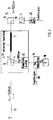
- FIG. 1 shows a transmission system with which an optical signal is to be transmitted from a point A to a point B.
- an optical transmitter not shown
- an optical receiver not shown
- the optical signal to be transmitted from A to B has a wavelength ⁇ 1 of 1540 nm.
- a monomode optical waveguide 15 is used as the transmission path, which has sufficiently good transmission properties at the wavelength ⁇ 1.
- the system according to FIG. 1 also contains a fiber optic amplifier 10, which consists of an Er3+-doped fiber piece 11, a wavelength-selective fiber optic coupler 12 and a pump light source 13.
- the coupler 12 has four connections 1 to 4. Its connection 1 is with the Er3+-doped fiber piece 11, its connector 2 via the optical fiber 15 connected to the end point B of the optical transmission path, and its connector 3 is connected to the pump light source 13 via an optical fiber piece.
- such a wavelength-selective fiber-optic coupler is to be used, which has the property of outputting the optical signal to be transmitted from A to B with the wavelength ⁇ 1 as undamped as possible at the coupler output 2 and the pump light generated by the pump light source 13 with the wavelength ⁇ Output p of 980 nm from the coupler input 3 with as little loss as possible at the coupler connection 1 in the direction of the doped fiber piece 11.
- the coupler connection 4 is not used.
- a modulation device 14 is provided according to the invention for the pump light source 13, which does this Pump light generated by the pump light source 13 is modulated with a modulation signal that contains the additional message signal.
- the modulation device 14 is preferably a frequency modulator which modulates an analog or digital additional signal applied to its modulation input ME, for example in the baseband position, of a carrier oscillation generated by a generator 18 with a carrier frequency f0, so that the modulation signal is thereby output at the frequency modulator 14 for the pump light source, ie the carrier oscillation frequency-modulated with the additional signal, appears.
- the pump light source 13 is to be considered in such a way that it contains the necessary control circuits for its laser, that is to say the so-called laser driver, and a control circuit for the DC bias of the laser.
- the modulation signal is fed into the laser driver of the pump light source 13 and thereby modulates the intensity of the light generated by the pump light source 13.
- the pump light source first generates unmodulated light and the modulation signal is used to modulate the pump light in a modulator connected downstream of the pump light source. In this case too, the pump light generated by the pump light source is modulated.
- the intensity of the pump light is so high that from the end of the fiber piece 11 remote from the coupler 12, a considerable proportion, which is not absorbed in the fiber piece 11, reaches the optical waveguide 15 and is transmitted from there towards the end point A.
- the additional signal can be transmitted in this way in the direction of the end point A up to the point at which the pump light can still be detected at a level sufficient for signal transmission.
- a fiber-optic wavelength-selective coupler 16 is inserted into the optical waveguide, which couples the pump light out of the optical waveguide 15, and an optical receiver 17 is connected to the output of the coupler 16 via an optical waveguide piece 19, at the output of which the electrical modulation signal impressed on the pump light appears, which is finally demodulated in an FM demodulator 20 so that the additional signal appears at its output.
- the invention thus uses the portion of the pump light that inevitably emerges from the fiber piece 11, which could only be suppressed with filters, for transmitting an additional signal from the location of the pump light source via the fiber piece 11 to the distant end point of the optical transmission path.
- the frequency f0 of the carrier used in the FM modulator 14 is selected in a suitable manner.
- a frequency f0 is suitable, which is much larger than the reciprocal of the lifespan of the Pump light excitable energy states of the Er3+ material of the fiber piece 11, that is, a frequency above 1MHz.
- FIG. 1 An example of an application for the new transmission system shown in FIG. 1 is when the optical transmission system is a cable television distribution system in which an electrical frequency multiplex signal with a bandwidth of 450 MHz is to be transmitted over the optical transmission path and in A front-end device, which distributes the optical signal transmitted up to it to a plurality of optical waveguides leading to individual subscribers, is the optical amplifier 10 shown, which then serves to amplify the optical signal before it is distributed to a plurality of optical waveguides.
- a return channel can be set up from the location of the pump light source to end point A, in practice the cable television center, via which an additional signal, for example a service channel signal, can be transmitted.
- the system described above has the so-called "counter-propagating configuration", in which the pump light, which couples the coupling light into the doped fiber piece, is arranged behind the amplifying fiber piece 11, based on the direction of transmission of the optical signal to be amplified.
- the so-called "co-propagating configuration” in which the coupler coupling the pump light into the doped fiber piece is arranged in front of the amplifying fiber piece in relation to the direction of transmission of the optical signal to be amplified. Even with such an arrangement, the non-absorbed pump light emerging from the doped fiber piece can be used to transmit an additional signal.
- the coupler 12 is located in the transmission direction of the signal to be transmitted from A to B before the Er3+-doped fiber piece 11. It also couples the actual transmission signal from its connection 1 to its connection 2 and the pump light from its connection 3 into the fiber piece 11, the latter via connection 2 instead of as in FIG. 1 via connection 1.
- the pump light emerging from the doped fiber piece 11 runs in the direction of the end point B of the transmission system, ie in the same direction as the first optical signal with the wavelength ⁇ 1 of 1540 nm, whereas it runs in the system of FIG. 1 opposite to it.
- the invention can thus be applied when an additional signal from the location of the pump light source of the transmission path towards the source of the first optical signal, i.e. the end point A, and the system according to FIG. 2 can be used if an additional signal from the location of the pump light source of the fiber optic amplifier in the direction of the sink of the first optical signal, i.e. to end point B, is to be transmitted.
- the combination of the two exemplary embodiments results in a fiber-optic amplifier, the doped fiber piece of which is fed from both sides by a pump light source, with the possibility of transmitting two additional signals in different directions of the transmission system from the location of the fiber-optic amplifier.
- wavelengths mentioned in the exemplary embodiment of the above description are only examples of wavelengths for which the available system components are suitable. Of course, other wavelengths can also be used, the signal wavelength ⁇ 1 always being in the range between 1520 and 1570 nm and the pump wavelength being 532 nm, 800 nm, 980 nm or 1480 nm.
Landscapes
- Physics & Mathematics (AREA)
- Electromagnetism (AREA)
- Engineering & Computer Science (AREA)
- Computer Networks & Wireless Communication (AREA)
- Signal Processing (AREA)
- Optical Communication System (AREA)
- Lasers (AREA)
Applications Claiming Priority (2)
| Application Number | Priority Date | Filing Date | Title |
|---|---|---|---|
| DE4036327 | 1990-11-15 | ||
| DE4036327A DE4036327A1 (de) | 1990-11-15 | 1990-11-15 | Optisches nachrichtenuebertragungssystem mit einem faseroptischen verstaerker |
Publications (3)
| Publication Number | Publication Date |
|---|---|
| EP0485813A2 true EP0485813A2 (fr) | 1992-05-20 |
| EP0485813A3 EP0485813A3 (en) | 1992-09-23 |
| EP0485813B1 EP0485813B1 (fr) | 1996-06-26 |
Family
ID=6418272
Family Applications (1)
| Application Number | Title | Priority Date | Filing Date |
|---|---|---|---|
| EP91118606A Expired - Lifetime EP0485813B1 (fr) | 1990-11-15 | 1991-10-31 | Système de télécommunications optique avec amplificateur en fibre optique |
Country Status (8)
| Country | Link |
|---|---|
| US (1) | US5285306A (fr) |
| EP (1) | EP0485813B1 (fr) |
| JP (1) | JPH04273624A (fr) |
| AT (1) | ATE139877T1 (fr) |
| AU (1) | AU647200B2 (fr) |
| CA (1) | CA2055274C (fr) |
| DE (1) | DE4036327A1 (fr) |
| ES (1) | ES2091272T3 (fr) |
Cited By (2)
| Publication number | Priority date | Publication date | Assignee | Title |
|---|---|---|---|---|
| EP0585126A3 (fr) * | 1992-08-28 | 1995-07-26 | Hughes Aircraft Co | Amplificateur bidirectionnel à fibre optique à grand rendement pour répétiteur de liaison de données pour le guidage des missiles. |
| US5453872A (en) * | 1993-07-26 | 1995-09-26 | Alcatel N.V. | Fiber-optic amplifier as wavelength converter |
Families Citing this family (11)
| Publication number | Priority date | Publication date | Assignee | Title |
|---|---|---|---|---|
| JP3137632B2 (ja) * | 1989-08-31 | 2001-02-26 | 富士通株式会社 | 光ファイバ増幅器を備えた光通信方式 |
| JP3425964B2 (ja) * | 1992-03-19 | 2003-07-14 | 富士通株式会社 | 誘導ブリルアン散乱を用いた光信号生成装置及び光伝送システム |
| DE4310292A1 (de) * | 1993-03-30 | 1994-10-06 | Sel Alcatel Ag | Faseroptischer Verstärker mit einer Vorrichtung zu Überwachung der Eingangsleistung |
| US5481391A (en) * | 1994-02-17 | 1996-01-02 | At&T Corp. | Optical fiber system and method for overcoming the effects of polarization gain anisotropy in a fiber amplifier |
| FR2721158B1 (fr) * | 1994-06-14 | 1996-07-12 | Alcatel Submarcom | Système de transmission sur une ligne à fibre optique sans répéteur, avec amplifications distante et locale. |
| US5532864A (en) * | 1995-06-01 | 1996-07-02 | Ciena Corporation | Optical monitoring channel for wavelength division multiplexed optical communication system |
| US5847853A (en) | 1995-12-29 | 1998-12-08 | Micron Technology, Inc. | Modulation and demodulation of light to facilitate transmission of information |
| EP0964487B1 (fr) * | 1997-02-25 | 2008-09-03 | Hitachi, Ltd. | Dispositif d'interconnexion optique |
| JP4647147B2 (ja) * | 2001-07-16 | 2011-03-09 | 富士通株式会社 | ラマン増幅を用いた光伝送方法および光伝送システム |
| US6731428B2 (en) * | 2001-11-21 | 2004-05-04 | Lucent Technologies Inc. | Pump monitoring and control in a fiber Raman amplifier |
| DE102004037549A1 (de) * | 2004-08-03 | 2006-03-16 | Deutsche Telekom Ag | Vorrichtung zur Erzeugung und Modulation eines hochfrequenten Signals |
Family Cites Families (8)
| Publication number | Priority date | Publication date | Assignee | Title |
|---|---|---|---|---|
| JPS6175326A (ja) * | 1984-09-21 | 1986-04-17 | Nec Corp | フアイバ内光増幅送信装置 |
| DE3827228A1 (de) * | 1988-08-11 | 1990-02-15 | Standard Elektrik Lorenz Ag | Sende/empfangsteil fuer ein bidirektionales kohaerent-optisches uebertragungssystem |
| JP3137632B2 (ja) * | 1989-08-31 | 2001-02-26 | 富士通株式会社 | 光ファイバ増幅器を備えた光通信方式 |
| IT1238032B (it) * | 1990-01-30 | 1993-06-23 | Pirelli Cavi Spa | Linea di telecomunicazione a fibre ottiche con canali separati di servizio |
| US5153762A (en) * | 1990-03-19 | 1992-10-06 | General Instrument Corporation | Method and apparatus for recovering AM channell signals distributed on an optical fiber |
| US5229876A (en) * | 1990-03-26 | 1993-07-20 | At&T Bell Laboratories | Telemetry for optical fiber amplifier repeater |
| US5035481A (en) * | 1990-08-23 | 1991-07-30 | At&T Bell Laboratories | Long distance soliton lightwave communication system |
| US5140656A (en) * | 1991-08-12 | 1992-08-18 | At&T Bell Laboratories | Soliton optical fiber communication system |
-
1990
- 1990-11-15 DE DE4036327A patent/DE4036327A1/de not_active Withdrawn
-
1991
- 1991-10-31 AT AT91118606T patent/ATE139877T1/de not_active IP Right Cessation
- 1991-10-31 ES ES91118606T patent/ES2091272T3/es not_active Expired - Lifetime
- 1991-10-31 EP EP91118606A patent/EP0485813B1/fr not_active Expired - Lifetime
- 1991-11-06 AU AU87068/91A patent/AU647200B2/en not_active Ceased
- 1991-11-13 CA CA002055274A patent/CA2055274C/fr not_active Expired - Fee Related
- 1991-11-13 JP JP3297199A patent/JPH04273624A/ja active Pending
- 1991-11-14 US US07/791,370 patent/US5285306A/en not_active Expired - Fee Related
Cited By (2)
| Publication number | Priority date | Publication date | Assignee | Title |
|---|---|---|---|---|
| EP0585126A3 (fr) * | 1992-08-28 | 1995-07-26 | Hughes Aircraft Co | Amplificateur bidirectionnel à fibre optique à grand rendement pour répétiteur de liaison de données pour le guidage des missiles. |
| US5453872A (en) * | 1993-07-26 | 1995-09-26 | Alcatel N.V. | Fiber-optic amplifier as wavelength converter |
Also Published As
| Publication number | Publication date |
|---|---|
| AU8706891A (en) | 1992-05-21 |
| ES2091272T3 (es) | 1996-11-01 |
| CA2055274C (fr) | 1998-01-27 |
| EP0485813A3 (en) | 1992-09-23 |
| DE4036327A1 (de) | 1992-05-21 |
| EP0485813B1 (fr) | 1996-06-26 |
| US5285306A (en) | 1994-02-08 |
| AU647200B2 (en) | 1994-03-17 |
| CA2055274A1 (fr) | 1992-05-16 |
| ATE139877T1 (de) | 1996-07-15 |
| JPH04273624A (ja) | 1992-09-29 |
Similar Documents
| Publication | Publication Date | Title |
|---|---|---|
| DE69127568T2 (de) | Telemetrie für optischen Faserzwischenverstärker | |
| DE69632720T2 (de) | Mehrfrequenzphasenmodulation für lichtwellenübertragungssystem | |
| EP0354567B1 (fr) | Ensemble émission-réception pour un système de communication bidirectionnel cohérent et optique | |
| DE69033858T2 (de) | Optischer Verstärker und optisches Übertragungssystem damit | |
| EP0613221B1 (fr) | Amplificateur à fibre optique à étages multiples | |
| EP0485813B1 (fr) | Système de télécommunications optique avec amplificateur en fibre optique | |
| DE2902789C2 (fr) | ||
| DE3232430A1 (de) | Optisches nachrichtenuebertragungssystem mit frequenzmodulation | |
| DE4019224A1 (de) | Funk-nachrichtenuebertragungssystem, insbesondere zellulares mobilfunksystem | |
| DE4430821A1 (de) | Optische Kommunikationsvorrichtung | |
| EP0790720B1 (fr) | Système CDMA de transmission optique de signaux codés en fréquence et récepteur optique associé | |
| DE4109683A1 (de) | System fuer optische signaluebertragung, insbesondere optisches kabelfernsehsystem, mit ueberwachungs- und dienstkanaleinrichtung | |
| DE4402428A1 (de) | Optisches Datenübertragungssystem | |
| DE69735839T2 (de) | Optische Übertragungseinrichtung und optisches Übertragungssystem | |
| DE69124301T2 (de) | Demodulator und Polarisationsdiversitätempfänger für kohärente optische Übertragung mit dem Demodulator | |
| DE69128537T2 (de) | Optisches Übertragungssystem | |
| EP0349766A2 (fr) | Système de transmission d'informations optique, concernant en particulier le raccordement d'abonnés | |
| EP0414333B1 (fr) | Réseau de données à fibres optiques | |
| DE3871604T2 (de) | Sender und senderempfaenger fuer ein kohaerentes optisches system. | |
| DE69020362T2 (de) | Verlustfreie optische komponente. | |
| EP0514686A2 (fr) | Système de transmission optique d'informations avec control optique d'un amplificateur optique ou avec conversion de longueur d'onde du signal optique | |
| DE69720450T2 (de) | Optische Dispersionskompensation | |
| DE69025822T2 (de) | Signalstrahlenpolarisationsregelung für hauptzustandsbidirektionale Übertragung durch eine optische Faser | |
| DE60036891T2 (de) | Lichtwellenübertragungssysteme unter Verwendung von optischen Halbleiterverstärkern | |
| DE4444218A1 (de) | Optische Sendeeinrichtung für ein optisches Nachrichtenübertragungssystem in Verbindung mit einem Funksystem |
Legal Events
| Date | Code | Title | Description |
|---|---|---|---|
| PUAI | Public reference made under article 153(3) epc to a published international application that has entered the european phase |
Free format text: ORIGINAL CODE: 0009012 |
|
| AK | Designated contracting states |
Kind code of ref document: A2 Designated state(s): AT BE CH DE ES FR GB IT LI NL SE |
|
| PUAL | Search report despatched |
Free format text: ORIGINAL CODE: 0009013 |
|
| AK | Designated contracting states |
Kind code of ref document: A3 Designated state(s): AT BE CH DE ES FR GB IT LI NL SE |
|
| RAP3 | Party data changed (applicant data changed or rights of an application transferred) |
Owner name: ALCATEL SEL AKTIENGESELLSCHAFT |
|
| 17P | Request for examination filed |
Effective date: 19921224 |
|
| RBV | Designated contracting states (corrected) |
Designated state(s): AT BE CH ES LI NL SE |
|
| REG | Reference to a national code |
Ref country code: DE Ref legal event code: 8566 |
|
| 17Q | First examination report despatched |
Effective date: 19950215 |
|
| GRAA | (expected) grant |
Free format text: ORIGINAL CODE: 0009210 |
|
| AK | Designated contracting states |
Kind code of ref document: B1 Designated state(s): AT BE CH ES LI NL SE |
|
| REF | Corresponds to: |
Ref document number: 139877 Country of ref document: AT Date of ref document: 19960715 Kind code of ref document: T |
|
| REG | Reference to a national code |
Ref country code: CH Ref legal event code: NV Representative=s name: JUERG ULRICH C/O ALCATEL STR AG |
|
| GRAH | Despatch of communication of intention to grant a patent |
Free format text: ORIGINAL CODE: EPIDOS IGRA |
|
| REG | Reference to a national code |
Ref country code: ES Ref legal event code: FG2A Ref document number: 2091272 Country of ref document: ES Kind code of ref document: T3 |
|
| PLBE | No opposition filed within time limit |
Free format text: ORIGINAL CODE: 0009261 |
|
| STAA | Information on the status of an ep patent application or granted ep patent |
Free format text: STATUS: NO OPPOSITION FILED WITHIN TIME LIMIT |
|
| 26N | No opposition filed | ||
| PGFP | Annual fee paid to national office [announced via postgrant information from national office to epo] |
Ref country code: CH Payment date: 20020918 Year of fee payment: 12 |
|
| PGFP | Annual fee paid to national office [announced via postgrant information from national office to epo] |
Ref country code: BE Payment date: 20020926 Year of fee payment: 12 |
|
| PGFP | Annual fee paid to national office [announced via postgrant information from national office to epo] |
Ref country code: NL Payment date: 20020930 Year of fee payment: 12 |
|
| PGFP | Annual fee paid to national office [announced via postgrant information from national office to epo] |
Ref country code: SE Payment date: 20021002 Year of fee payment: 12 |
|
| PGFP | Annual fee paid to national office [announced via postgrant information from national office to epo] |
Ref country code: AT Payment date: 20021003 Year of fee payment: 12 |
|
| PGFP | Annual fee paid to national office [announced via postgrant information from national office to epo] |
Ref country code: ES Payment date: 20021017 Year of fee payment: 12 |
|
| PG25 | Lapsed in a contracting state [announced via postgrant information from national office to epo] |
Ref country code: LI Free format text: LAPSE BECAUSE OF NON-PAYMENT OF DUE FEES Effective date: 20031031 Ref country code: CH Free format text: LAPSE BECAUSE OF NON-PAYMENT OF DUE FEES Effective date: 20031031 Ref country code: BE Free format text: LAPSE BECAUSE OF NON-PAYMENT OF DUE FEES Effective date: 20031031 Ref country code: AT Free format text: LAPSE BECAUSE OF NON-PAYMENT OF DUE FEES Effective date: 20031031 |
|
| PG25 | Lapsed in a contracting state [announced via postgrant information from national office to epo] |
Ref country code: SE Free format text: LAPSE BECAUSE OF NON-PAYMENT OF DUE FEES Effective date: 20031101 |
|
| PG25 | Lapsed in a contracting state [announced via postgrant information from national office to epo] |
Ref country code: ES Free format text: LAPSE BECAUSE OF NON-PAYMENT OF DUE FEES Effective date: 20031103 |
|
| BERE | Be: lapsed |
Owner name: *ALCATEL SEL A.G. Effective date: 20031031 |
|
| PG25 | Lapsed in a contracting state [announced via postgrant information from national office to epo] |
Ref country code: NL Free format text: LAPSE BECAUSE OF NON-PAYMENT OF DUE FEES Effective date: 20040501 |
|
| REG | Reference to a national code |
Ref country code: CH Ref legal event code: PL |
|
| EUG | Se: european patent has lapsed | ||
| NLV4 | Nl: lapsed or anulled due to non-payment of the annual fee |
Effective date: 20040501 |
|
| REG | Reference to a national code |
Ref country code: ES Ref legal event code: FD2A Effective date: 20031103 |