EP0485832A2 - Ensemble projecteur pour véhicules - Google Patents
Ensemble projecteur pour véhicules Download PDFInfo
- Publication number
- EP0485832A2 EP0485832A2 EP91118718A EP91118718A EP0485832A2 EP 0485832 A2 EP0485832 A2 EP 0485832A2 EP 91118718 A EP91118718 A EP 91118718A EP 91118718 A EP91118718 A EP 91118718A EP 0485832 A2 EP0485832 A2 EP 0485832A2
- Authority
- EP
- European Patent Office
- Prior art keywords
- reflector
- unit according
- carrier part
- headlight unit
- section
- Prior art date
- Legal status (The legal status is an assumption and is not a legal conclusion. Google has not performed a legal analysis and makes no representation as to the accuracy of the status listed.)
- Granted
Links
- 230000003287 optical effect Effects 0.000 claims abstract description 17
- 239000002184 metal Substances 0.000 claims 1
- 238000011161 development Methods 0.000 description 3
- 230000018109 developmental process Effects 0.000 description 3
- 230000002093 peripheral effect Effects 0.000 description 2
- 238000009825 accumulation Methods 0.000 description 1
- 230000001154 acute effect Effects 0.000 description 1
- 238000010276 construction Methods 0.000 description 1
- 230000005484 gravity Effects 0.000 description 1
- 230000017525 heat dissipation Effects 0.000 description 1
Images

Classifications
-
- B—PERFORMING OPERATIONS; TRANSPORTING
- B60—VEHICLES IN GENERAL
- B60Q—ARRANGEMENT OF SIGNALLING OR LIGHTING DEVICES, THE MOUNTING OR SUPPORTING THEREOF OR CIRCUITS THEREFOR, FOR VEHICLES IN GENERAL
- B60Q1/00—Arrangement of optical signalling or lighting devices, the mounting or supporting thereof or circuits therefor
- B60Q1/0029—Spatial arrangement
- B60Q1/0041—Spatial arrangement of several lamps in relation to each other
-
- B—PERFORMING OPERATIONS; TRANSPORTING
- B60—VEHICLES IN GENERAL
- B60Q—ARRANGEMENT OF SIGNALLING OR LIGHTING DEVICES, THE MOUNTING OR SUPPORTING THEREOF OR CIRCUITS THEREFOR, FOR VEHICLES IN GENERAL
- B60Q1/00—Arrangement of optical signalling or lighting devices, the mounting or supporting thereof or circuits therefor
- B60Q1/02—Arrangement of optical signalling or lighting devices, the mounting or supporting thereof or circuits therefor the devices being primarily intended to illuminate the way ahead or to illuminate other areas of way or environments
- B60Q1/04—Arrangement of optical signalling or lighting devices, the mounting or supporting thereof or circuits therefor the devices being primarily intended to illuminate the way ahead or to illuminate other areas of way or environments the devices being headlights
- B60Q1/06—Arrangement of optical signalling or lighting devices, the mounting or supporting thereof or circuits therefor the devices being primarily intended to illuminate the way ahead or to illuminate other areas of way or environments the devices being headlights adjustable, e.g. remotely-controlled from inside vehicle
- B60Q1/076—Arrangement of optical signalling or lighting devices, the mounting or supporting thereof or circuits therefor the devices being primarily intended to illuminate the way ahead or to illuminate other areas of way or environments the devices being headlights adjustable, e.g. remotely-controlled from inside vehicle by electrical means including means to transmit the movements, e.g. shafts or joints
-
- F—MECHANICAL ENGINEERING; LIGHTING; HEATING; WEAPONS; BLASTING
- F21—LIGHTING
- F21S—NON-PORTABLE LIGHTING DEVICES; SYSTEMS THEREOF; VEHICLE LIGHTING DEVICES SPECIALLY ADAPTED FOR VEHICLE EXTERIORS
- F21S41/00—Illuminating devices specially adapted for vehicle exteriors, e.g. headlamps
- F21S41/20—Illuminating devices specially adapted for vehicle exteriors, e.g. headlamps characterised by refractors, transparent cover plates, light guides or filters
- F21S41/29—Attachment thereof
- F21S41/295—Attachment thereof specially adapted to projection lenses
-
- F—MECHANICAL ENGINEERING; LIGHTING; HEATING; WEAPONS; BLASTING
- F21—LIGHTING
- F21S—NON-PORTABLE LIGHTING DEVICES; SYSTEMS THEREOF; VEHICLE LIGHTING DEVICES SPECIALLY ADAPTED FOR VEHICLE EXTERIORS
- F21S41/00—Illuminating devices specially adapted for vehicle exteriors, e.g. headlamps
- F21S41/30—Illuminating devices specially adapted for vehicle exteriors, e.g. headlamps characterised by reflectors
- F21S41/39—Attachment thereof
Definitions
- the invention relates to a headlight unit for vehicles with the features according to the preamble of claim 1.
- attachment points are formed on the first and second reflector, of which which directly a rigid connection between the adjacent sides of both reflectors and others the connection from the first and second reflector to the housing produce.
- each reflector is also part of the other reflector. Because of this and because the second reflector forms a heavy optical unit together with the frame supporting the diaphragm and the lens, it is not ensured that the reflectors are kept vibration-free in the housing during driving. Tensioning forces can also act on the shell of the reflector. Furthermore, it is disadvantageous that the reflectors cannot be used for other headlight units because of their fastening points which are specially designed for the headlight type.
- the two reflectors are arranged relative to one another in such a way that the lens of the optical unit and the front edge of the first reflector are at a sufficiently large or approximately the same distance from the lens that covers them together.
- the fastening points between the two reflectors must be designed differently.
- the object of the invention is to design the headlight unit according to the preamble of claim 1 such that the first and second reflectors are connected to the housing independently of one another, ie not a reflector is at the same time the carrier part of the other reflector, without the number of components being increased and a sufficiently large distance being able to be maintained between the lens of the optical unit and between the front edge of the first reflector and the lens, and furthermore the attachment points of the optical unit in one the center of gravity of the optical unit is as close as possible.
- This object is achieved by the features of the characterizing part of claim 1.
- the first reflector can be made very thin-walled and thus have a correspondingly low weight.
- both reflectors are in a very precise position relative to one another, since the first reflector is fastened to the section of the carrier part serving as a receptacle for the lamp and the second reflector is fastened to the carrier part with its outer edge section.
- the outer edge section of the second reflector is in a very precise position with respect to the optical axis, since it also serves to fasten the frame carrying the diaphragm and lens.
- a solution is created by means of which the additionally adjustable reflector can be adjusted in a very precise position with respect to the reflector adjacent to it.
- a headlamp unit is created in which the first reflector can be connected very stably to the carrier part, without sink marks having to occur on its reflection surface due to material accumulation.
- the first reflector is fixed very precisely to the section of the carrier part which serves as a receiving element for the incandescent lamp.
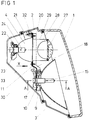
- the paraboloid-shaped first reflector (3) and the ellipsoid-shaped second reflector (4) are inserted into the housing (2) covered by the lens (1).
- the first reflector is made of plastic and has the Part the opening (5), which is surrounded by the collar (6) projecting outwards.
- the radially outwardly projecting flange is formed around the outer side surface of the collar (6) at a distance from the free end of the collar (6).
- projections (8) designed as hollow pegs are formed on the circumference of the flange (7), the longitudinal axis of which runs parallel to the optical axis of the reflector (3).
- the plate-shaped support part (11) bears on the end face of the collar (6) facing away from the reflector (3), the narrow side face of the walls (9) and the end face of the pins (8).
- the reflector (3) is precisely fixed to the carrier part by the elevations (10) of the walls (9) which engage in correspondingly large openings in the carrier part (11).
- the first reflector is fixed to the section (13) on the section (13) of the support part by the fastening screws (12) which pass through openings in the section (13) and engage in the hollow pins (8).
- the section (13) has the opening (14) which overlaps the opening (5) of the first reflector (3) and serves to receive the lamp (15).
- the lamp (15) rests with its base plate (16) on the side surface of the section (13) of the carrier part (11) facing away from the reflector.
- the base plate (16) is pressed against the section (13) by a bow-shaped retaining spring (17) which is pivotably attached to the section (13).
- the cross section of the carrier part is U-shaped, the legs (18) pointing in the light exit direction and the distance between the legs (18) being approximately as large as the distance between the flats (19) of the first reflector, which is approximately rectangular in the light exit surface (3).
- the second reflector (4) arranged on the reflector is fastened to the section (20) of the carrier part (11) extending towards it with its outer peripheral edge section (21).
- the second reflector has the opening (22) and the receiving element (23) for the lamp (24) at the apex.
- the carrier part (11) has an opening (25) corresponding to the light exit surface of the second reflector (4) and fastening openings (26) for the second reflector (4) which are introduced at the edge section surrounding the opening.
- the second reflector (4) forms an optical unit together with the frame (29) which supports the lens (27) and the diaphragm (28) and which is fastened to the outer peripheral edge section (21) of the second reflector.
- the optical unit is designed to be significantly lower than the first reflector (3) when viewed in the light exit direction. For this reason and because the lens (1) is inclined from the first reflector to the optical unit towards the rear of the headlight, the step (30) is introduced between the first reflector and the second reflector in the carrier part (11) so that the Lens of the optical unit and the outer circumferential edge of the first reflector is approximately the same distance from the lens (1).
- a fastening point (not shown) is introduced into one of the two legs (18) of the U-shaped carrier part (11) and is used to fasten the carrier part (11) to the housing.
- the two tabs (32) are formed with fastening points which serve to fasten the carrier part to the housing.
- the two axes which run perpendicular to one another and which pass through the fastening points are not shown in the drawing.
- the rear of the housing has an opening which is covered by the cap (33).
Landscapes
- Engineering & Computer Science (AREA)
- Mechanical Engineering (AREA)
- General Engineering & Computer Science (AREA)
- Non-Portable Lighting Devices Or Systems Thereof (AREA)
Applications Claiming Priority (2)
| Application Number | Priority Date | Filing Date | Title |
|---|---|---|---|
| DE4036031A DE4036031C1 (fr) | 1990-11-13 | 1990-11-13 | |
| DE4036031 | 1990-11-13 |
Publications (3)
| Publication Number | Publication Date |
|---|---|
| EP0485832A2 true EP0485832A2 (fr) | 1992-05-20 |
| EP0485832A3 EP0485832A3 (en) | 1992-07-01 |
| EP0485832B1 EP0485832B1 (fr) | 1994-11-02 |
Family
ID=6418137
Family Applications (1)
| Application Number | Title | Priority Date | Filing Date |
|---|---|---|---|
| EP91118718A Expired - Lifetime EP0485832B1 (fr) | 1990-11-13 | 1991-11-04 | Ensemble projecteur pour véhicules |
Country Status (6)
| Country | Link |
|---|---|
| US (1) | US5136482A (fr) |
| EP (1) | EP0485832B1 (fr) |
| BR (1) | BR9104899A (fr) |
| CS (1) | CS342391A3 (fr) |
| DE (1) | DE4036031C1 (fr) |
| ES (1) | ES2062642T3 (fr) |
Families Citing this family (16)
| Publication number | Priority date | Publication date | Assignee | Title |
|---|---|---|---|---|
| DE4414902C1 (de) * | 1994-04-28 | 1995-06-01 | Hella Kg Hueck & Co | Abdeckteil für ein Reflektoren aufnehmendes Gehäuse einer Leuchteneinheit für Fahrzeuge |
| JP3898312B2 (ja) * | 1997-11-11 | 2007-03-28 | 株式会社小糸製作所 | 車輌用前照灯 |
| DE19824053A1 (de) * | 1998-05-29 | 1999-12-02 | Hella Kg Hueck & Co | Beleuchtungseinrichtung für Fahrzeuge |
| DE19832466A1 (de) * | 1998-07-18 | 2000-02-17 | Volkswagen Ag | Scheinwerferanordnung nach dem Profjektionstyp für ein Kraftfahrzeug |
| IT244305Y1 (it) * | 1998-10-14 | 2002-03-11 | Magneti Marelli Spa | Proiettore modulare ad ottiche multiple per veicoli |
| DE19852306B4 (de) * | 1998-11-12 | 2008-12-04 | Volkswagen Ag | Scheinwerferanordnung für Kraftfahrzeuge |
| DE19933663B4 (de) * | 1999-07-17 | 2012-05-03 | Automotive Lighting Reutlingen Gmbh | Scheinwerfer für Fahrzeuge |
| US6652130B2 (en) * | 2001-01-25 | 2003-11-25 | Koito Manufacturing Co., Ltd. | Vehicle headlamp |
| US8021031B2 (en) * | 2007-02-01 | 2011-09-20 | Ford Global Technologies, Llc | Automotive head lamp bulb shield |
| DE102008045764A1 (de) * | 2008-09-04 | 2010-03-11 | Hella Kgaa Hueck & Co. | Scheinwerfer |
| JP5249886B2 (ja) * | 2009-09-16 | 2013-07-31 | 本田技研工業株式会社 | 自動二輪車用ヘッドランプ |
| DE102011052484A1 (de) | 2011-08-08 | 2013-02-14 | Hella Kgaa Hueck & Co. | Tragrahmen für die Lagerung eines Scheinwerfers eines Fahrzeugs |
| JP2015069788A (ja) * | 2013-09-27 | 2015-04-13 | トヨタ自動車株式会社 | 車両用ランプ構造 |
| DE102021112674A1 (de) * | 2021-05-17 | 2022-11-17 | HELLA GmbH & Co. KGaA | Scheinwerfer für ein Fahrzeug mit neuartiger Grundstruktur |
| WO2022242844A1 (fr) * | 2021-05-19 | 2022-11-24 | HELLA GmbH & Co. KGaA | Bâti de support pour un dispositif d'éclairage de véhicule |
| CN119682641B (zh) * | 2024-12-24 | 2025-10-03 | 岚图汽车科技有限公司 | 带氛围灯的汽车顶棚 |
Family Cites Families (3)
| Publication number | Priority date | Publication date | Assignee | Title |
|---|---|---|---|---|
| FR2601111B1 (fr) * | 1986-07-07 | 1988-10-21 | Cibie Projecteurs | Projecteur de vehicule automobile, a deux miroirs reglables mutuellement |
| DE3703129A1 (de) * | 1987-02-03 | 1988-08-11 | Hella Kg Hueck & Co | Scheinwerfereinheit fuer fahrzeuge |
| JPS6418739A (en) * | 1987-07-13 | 1989-01-23 | Koito Mfg Co Ltd | Headlamp mounting device |
-
1990
- 1990-11-13 DE DE4036031A patent/DE4036031C1/de not_active Expired - Lifetime
-
1991
- 1991-11-04 EP EP91118718A patent/EP0485832B1/fr not_active Expired - Lifetime
- 1991-11-04 ES ES91118718T patent/ES2062642T3/es not_active Expired - Lifetime
- 1991-11-12 CS CS913423A patent/CS342391A3/cs unknown
- 1991-11-12 BR BR919104899A patent/BR9104899A/pt not_active IP Right Cessation
- 1991-11-12 US US07/789,902 patent/US5136482A/en not_active Expired - Fee Related
Also Published As
| Publication number | Publication date |
|---|---|
| US5136482A (en) | 1992-08-04 |
| BR9104899A (pt) | 1992-06-23 |
| EP0485832B1 (fr) | 1994-11-02 |
| EP0485832A3 (en) | 1992-07-01 |
| CS342391A3 (en) | 1992-05-13 |
| DE4036031C1 (fr) | 1992-02-27 |
| ES2062642T3 (es) | 1994-12-16 |
Similar Documents
| Publication | Publication Date | Title |
|---|---|---|
| DE4036031C1 (fr) | ||
| EP0637715A1 (fr) | Dispositif de fixation de lampe sur un réflecteur de projecteur de véhicule | |
| DE4428357A1 (de) | Kittlos gesockelte Halogenglühlampe | |
| DE3903631C1 (fr) | ||
| DE3939710C1 (fr) | ||
| DE19546271B4 (de) | Scheinwerfer für Fahrzeuge mit einem verschwenkbaren Reflektor | |
| DE2353322A1 (de) | Scheinwerfer fuer kraftfahrzeuge | |
| EP0590439B1 (fr) | Projecteur pour véhicules | |
| EP0008004A1 (fr) | Appareil d'éclairage à réflecteur amovible | |
| DE3518404C2 (fr) | ||
| EP0696703A1 (fr) | Phare de véhicule | |
| EP0636831B1 (fr) | Ecran pour un phare non éblouissant de véhicule automobile | |
| EP0590454A2 (fr) | Projecteur pour véhicules | |
| EP0268759A2 (fr) | Phare du type projecteur pour véhicules | |
| DE4438491C1 (de) | Leuchte für Fahrzeuge | |
| DE4445187A1 (de) | Scheinwerfer für Fahrzeuge | |
| DE3300337C2 (de) | Vorrichtung zum Haltern eines langgestreckten Leuchtenunterteils an einem langgestreckten Leuchtenoberteil | |
| DE29821068U1 (de) | Scheinwerfer für Fahrzeuge | |
| DE9312695U1 (de) | Einstellanordnung für die Verschwenkbarkeit eines Reflektors eines Kraftfahrzeugscheinwerfers | |
| DE1505379A1 (de) | Beleuchtungseinrichtung fuer Fahrzeuge | |
| DE19511164A1 (de) | Fahrzeugleuchte mit Freiformflächenreflektor und brillanter transparenter Abdeckscheibe | |
| DE4426162C1 (de) | Kraftfahrzeugscheinwerfer mit Lampenhaltevorrichtung | |
| EP1329931B1 (fr) | Lampe compacte à décharge à basse pression | |
| EP0791502A2 (fr) | Feu arrière pour véhicule | |
| DE3920579C2 (fr) |
Legal Events
| Date | Code | Title | Description |
|---|---|---|---|
| PUAI | Public reference made under article 153(3) epc to a published international application that has entered the european phase |
Free format text: ORIGINAL CODE: 0009012 |
|
| PUAL | Search report despatched |
Free format text: ORIGINAL CODE: 0009013 |
|
| AK | Designated contracting states |
Kind code of ref document: A2 Designated state(s): ES FR GB IT |
|
| AK | Designated contracting states |
Kind code of ref document: A3 Designated state(s): ES FR GB IT |
|
| 17P | Request for examination filed |
Effective date: 19921112 |
|
| 17Q | First examination report despatched |
Effective date: 19940420 |
|
| GRAA | (expected) grant |
Free format text: ORIGINAL CODE: 0009210 |
|
| ITF | It: translation for a ep patent filed | ||
| AK | Designated contracting states |
Kind code of ref document: B1 Designated state(s): ES FR GB IT |
|
| REG | Reference to a national code |
Ref country code: ES Ref legal event code: FG2A Ref document number: 2062642 Country of ref document: ES Kind code of ref document: T3 |
|
| GBT | Gb: translation of ep patent filed (gb section 77(6)(a)/1977) |
Effective date: 19941223 |
|
| ET | Fr: translation filed | ||
| PLBE | No opposition filed within time limit |
Free format text: ORIGINAL CODE: 0009261 |
|
| STAA | Information on the status of an ep patent application or granted ep patent |
Free format text: STATUS: NO OPPOSITION FILED WITHIN TIME LIMIT |
|
| 26N | No opposition filed | ||
| PGFP | Annual fee paid to national office [announced via postgrant information from national office to epo] |
Ref country code: GB Payment date: 19991020 Year of fee payment: 9 |
|
| PGFP | Annual fee paid to national office [announced via postgrant information from national office to epo] |
Ref country code: ES Payment date: 19991112 Year of fee payment: 9 |
|
| PGFP | Annual fee paid to national office [announced via postgrant information from national office to epo] |
Ref country code: FR Payment date: 19991117 Year of fee payment: 9 |
|
| PG25 | Lapsed in a contracting state [announced via postgrant information from national office to epo] |
Ref country code: GB Free format text: LAPSE BECAUSE OF NON-PAYMENT OF DUE FEES Effective date: 20001104 |
|
| PG25 | Lapsed in a contracting state [announced via postgrant information from national office to epo] |
Ref country code: ES Free format text: LAPSE BECAUSE OF NON-PAYMENT OF DUE FEES Effective date: 20001105 |
|
| GBPC | Gb: european patent ceased through non-payment of renewal fee |
Effective date: 20001104 |
|
| PG25 | Lapsed in a contracting state [announced via postgrant information from national office to epo] |
Ref country code: FR Free format text: LAPSE BECAUSE OF NON-PAYMENT OF DUE FEES Effective date: 20010731 |
|
| REG | Reference to a national code |
Ref country code: FR Ref legal event code: ST |
|
| REG | Reference to a national code |
Ref country code: ES Ref legal event code: FD2A Effective date: 20011214 |
|
| PG25 | Lapsed in a contracting state [announced via postgrant information from national office to epo] |
Ref country code: IT Free format text: LAPSE BECAUSE OF NON-PAYMENT OF DUE FEES;WARNING: LAPSES OF ITALIAN PATENTS WITH EFFECTIVE DATE BEFORE 2007 MAY HAVE OCCURRED AT ANY TIME BEFORE 2007. THE CORRECT EFFECTIVE DATE MAY BE DIFFERENT FROM THE ONE RECORDED. Effective date: 20051104 |